Maroula Bacharidou
MAS.863 | How to Make (Almost) Anything
Making an in-circuit programmer
and programming it
*1. Assignment
___a. milling
___b. soldering
___c. programming
*
1. Assignment
This week's assignment was to a) mill a PCB using the MDX20 Roland Modela and b) solder the components and program our board. I learned how to make the hello.ISP.44 in-system programmer, with which you can program microcontrollers on other boards.
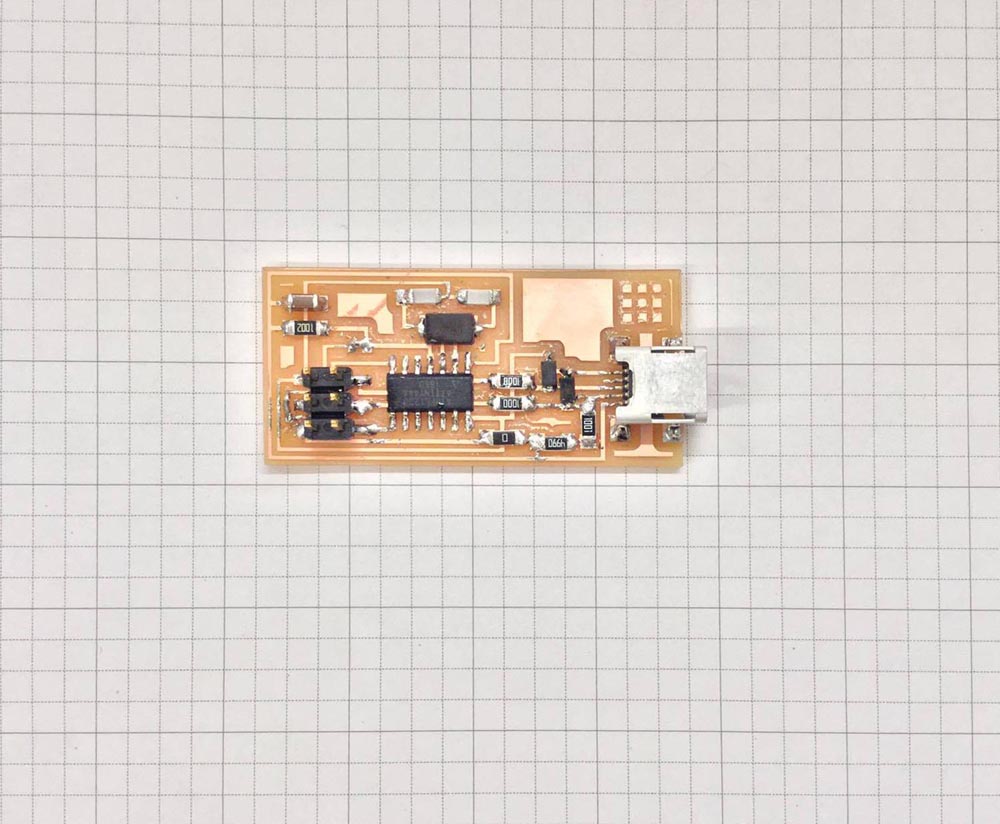
Figure 1. My hello.ISP.44 board
___a. milling
or, how to millAs I was new to electronics, I followed the instructions given during class and at the CBA shop meeting. From the moment I started working on my PCB, I realized that making your own PCB requires time and concentration, precision and patience, especially in the soldering part. That's the first lesson I learned. The rest of the lessons are illustrated below:
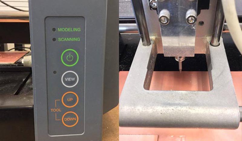
Figure 2. Placing the board in the modela.
- Placing the board in thw Roland Modela:place another layer (a board you are not going to use, probably larger) under the board, take a clean new board (FR1, copper thickness 0.04mm) and fix it on the substrate with a double sided tape; make sure that the board is taped flat on the larger board (I aligned the board with the bottom left corner of the plate, which is the origin point of the Modela).
- Zeroing the mill: run the fab module for Roland Modela; count the distance of the board from the bottom left corner of the Modela plate and write them down for the second milling with the modela; loosen the screw manually; loosen the tip and put it down (after one failed attempt, I pressed it sli(iii)ghtly more towards the modela surface); tighten the first screw a little bit, then fully tighten the other screw and go back and tighten the first one.
- Sending the file: load the correct file and select the correct setting (mill traces or cut board); press calculate; send it.
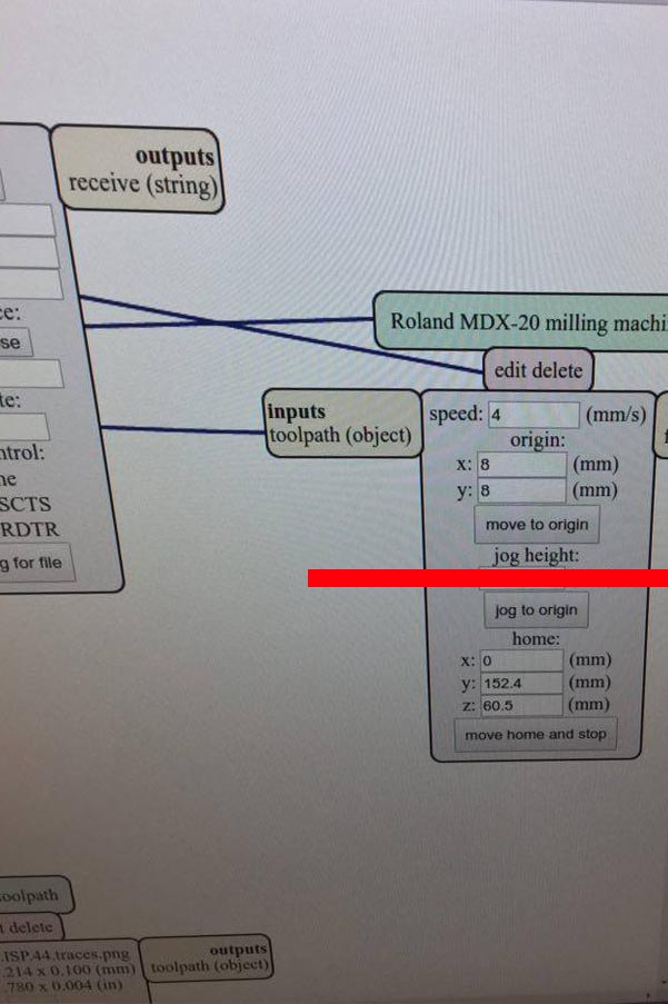
Figure 3. Sending the files to the Roland Modela.
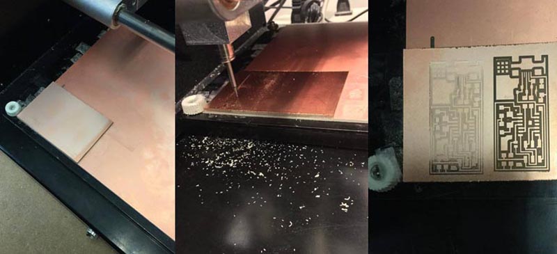
Figure 4. First and second print of the board. The right is the one that i slightly pressed the mill towards the board before tightening it to the machine.
___b. soldering
The most pleasurable part of the PCB making process. I was glad to raelize that I would have to solder many other boards until the end of the class! The technique I used was: 1. putting a small drop of solder on the board; 2. holding the component with a tweezer on the solder; 3. heating the solder with the iron and connect it to the component; 4. soldering the other side of the component. In order to prevent solder from extending beyond the copper paths, a good idea is to use flux. However, I thought of the task as a challenge and did not use flux at all.
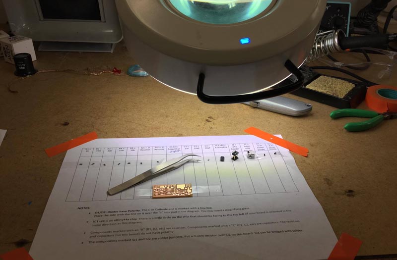
Figure 5. Ready to solder!
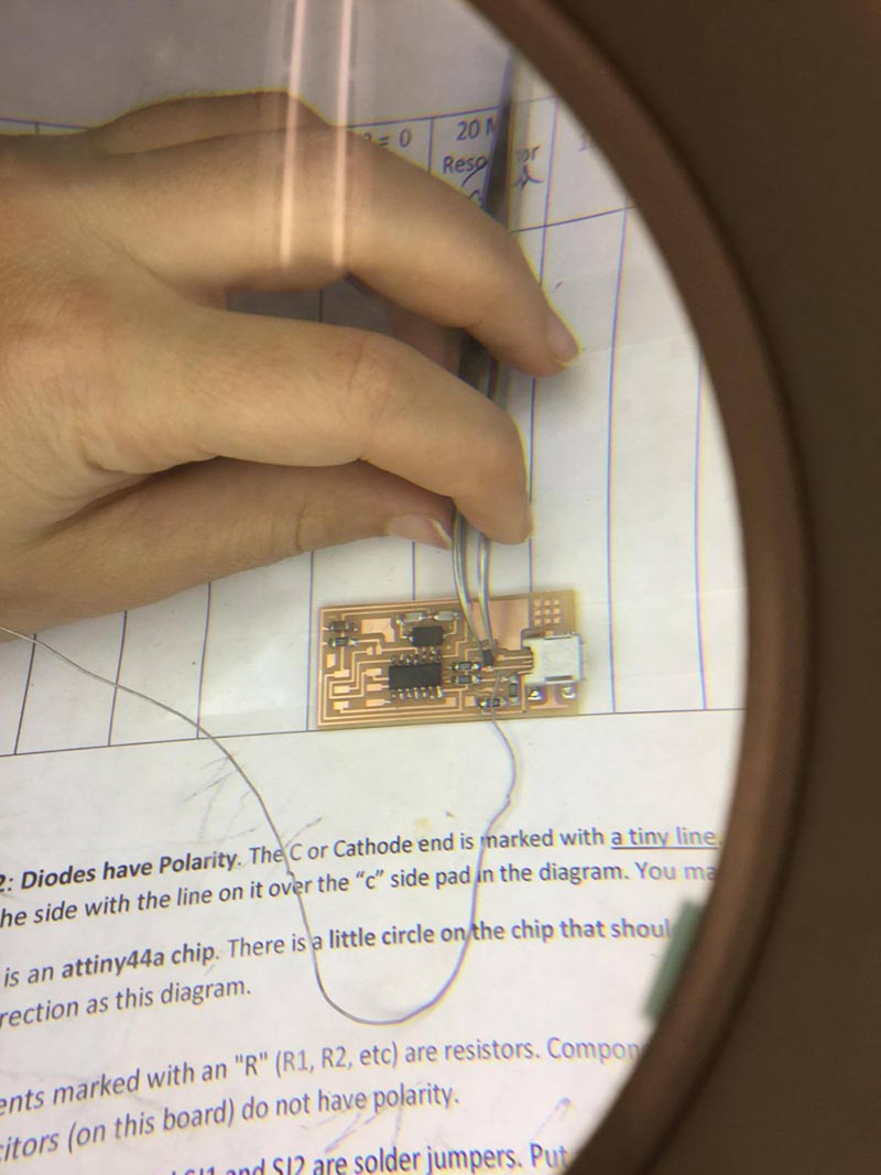
Figure 6. Soldering is zen(ish)
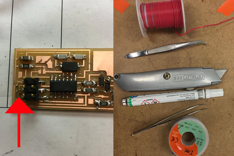
Figure 7. "Hacked" the board cutting a thin cable to relace the (unfortunately cut) copper layer
___c. programming
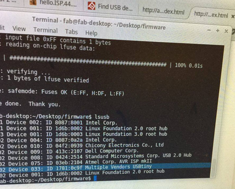
To program my board, I had to download firmware.zip and to run the following commands: make clean, make hex, (sudo) make fuse, (sudo) make program. After desoldering the two (JS1 and JS2) jumpers from Neil's board, the board was ready to use.