Maroula Bacharidou
MAS.863 | How to Make (Almost) Anything
Qubricks
Press-fit bricks that interlock with each other
*1. Idea
2. Hands-on experimentations and realizations
3. Design
4. Fabrication
*
1. Idea
This week's assignment was to cut something on the vinylcutter, to make a parametric press-fit construction kit, and to document both processes. I saw this assignment as an opportunity to produce my first Qubricks, which are the space-filling bricks that I designed for my final project. As the geometry of Qubricks is quite complex and their fabrication with cardboard surfaces and joints would require the use (and manual assembly) of a lot of parts, I tried to think of a way of fabricating them with the least possible parts. After experimenting on paper and slicing up a fair amount of corrugated boxes that accompanied my move to Cambridge, I came up with the idea for a foldable prototype made from just one piece of cardboard.
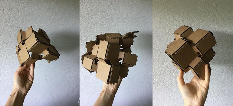
Figure 3. Folding and assembling the brick
2. Hands-on experimentations and realizations
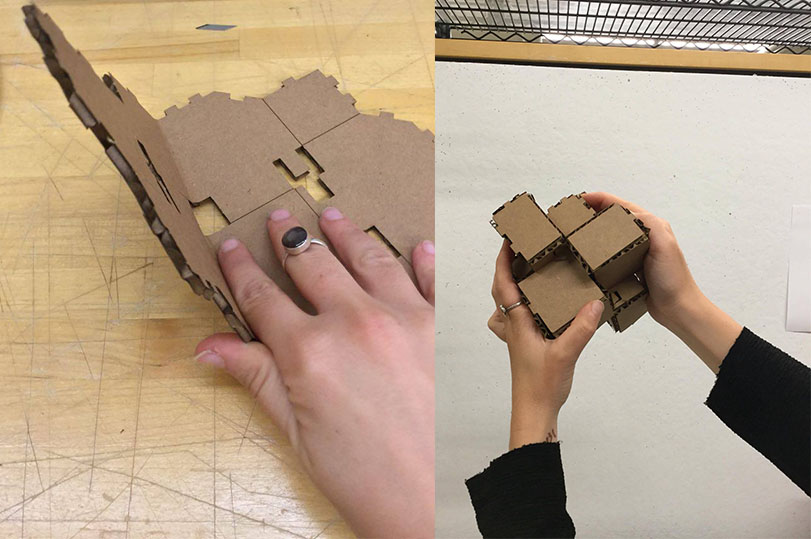
I started designing mostly with slicing up cardboards, marking, and folding them rather than sketching or 3d modelling. This hands-on process helped me a lot to understand how should I design the construction kit later using modeling software.
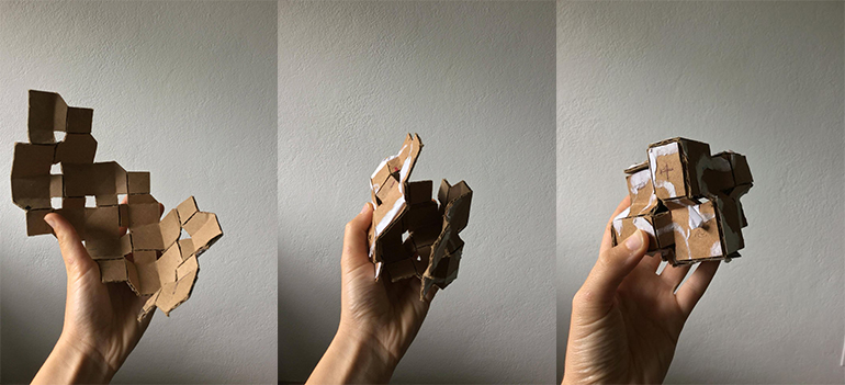
Figure 4. Initial idea: a net whose sides press-fit. This is the original, not-laser-cutted version of the folding-fitting process shown above.
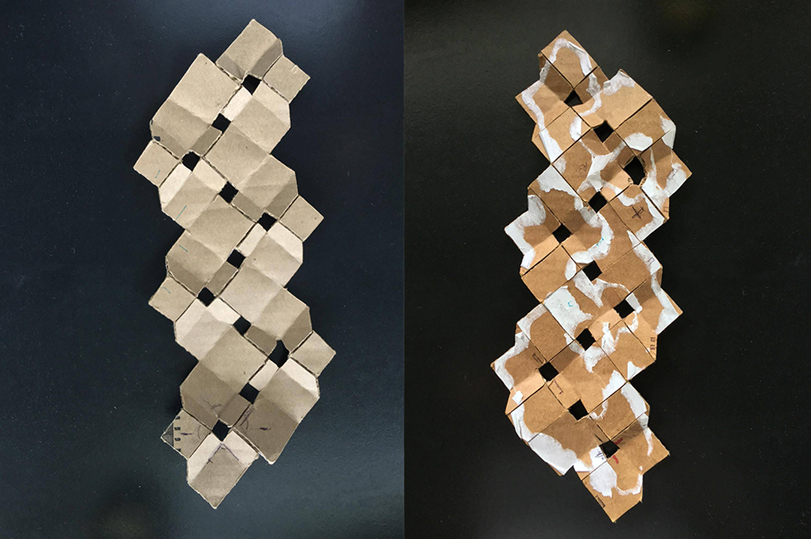
Figure 5. Hand-cut net, sides a and b.
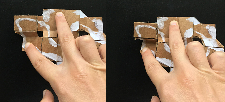
Figure 6. How the sides fold. The holes gave the solution.
3. Design
My hands-on start gave me a pretty good idea of the problems that would come up during the design process. Matching the edges, giving the right thicknesses to the joints, and setting dimensions that would not make the cardboard deform as it folds were my main goals. I designed the kit with two basic parameters in mind: the thickness of the cardboard and the fact that it will fold, so I had to use dimensions that will not make it tear off. I used Rhinoceros bor the design of the initial sketch, then Grasshopper to manage the changes in the sizes of the sides, keeping the joint width equal to the thickness of the cardboard. Using my hands to improve and evaluate what I was designing was essential to the design of the final object.
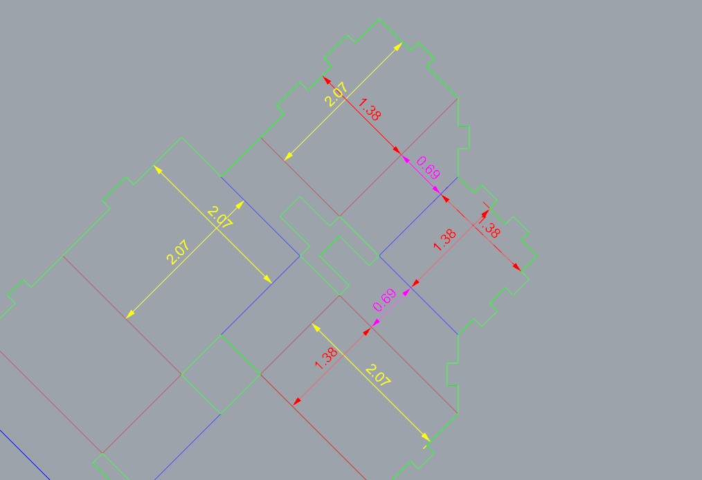
Figure 8. The sides are divided into four rectangles, the two of them being squares -a small and a big one.
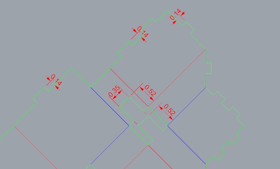
Figure 9. The sides fit together through joints that have the width of the cardboard.
4. Fabrication
The kit wasn't cut as I was expecting from the first time. I was confused on which printers settings I should use, as I used two different printers for my tests - the 60W and the 120W EPILOG from the Architecture shop. I tried different speed and power modes close to the range of the instructions, and I realized that the 35/30 mode does not work for all cases. A tricky part of the fabrication process were the scores on the back side of the cardboard. During the first test, they were not in the right position, and the speed/power I used cut the net into pieces. The second time, I taped the cardboard on the cutting bed, cut a sample AND a rectangle around it, scored the back side, took the rectangle out, flipped it and recut it. The scores were perfectly aligned this time, and the cutting/scoring were as sharp/mild as they shoyuld be. For the scores, I used 73/20 power/speed, and for the cuts I did two passes of 25/30.
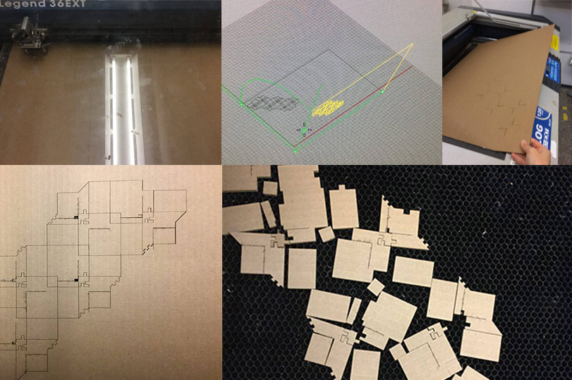
Figure 10. First test: fail happening under the glass.
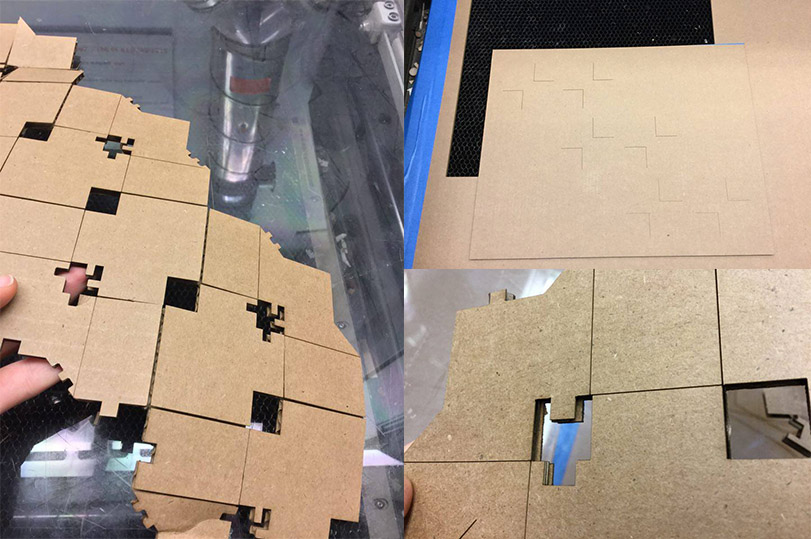
Figure 11. Final cutting, correct this time.
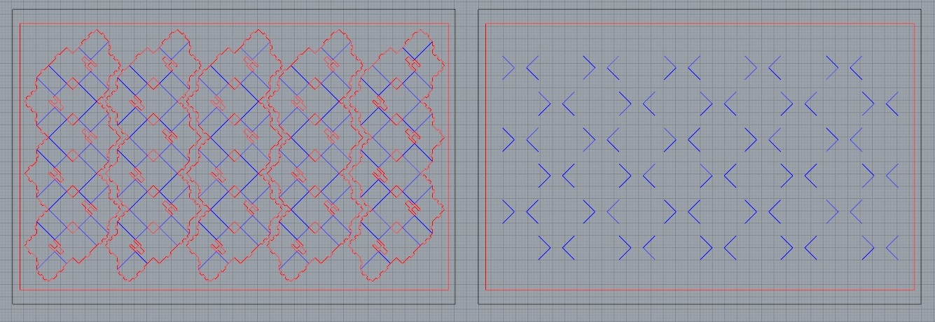
Figure 12. The fold scores, line cuts, and outlines in Rhinoceros (the right one flipped in order to fold the other side of the net).
Ready for the final print.
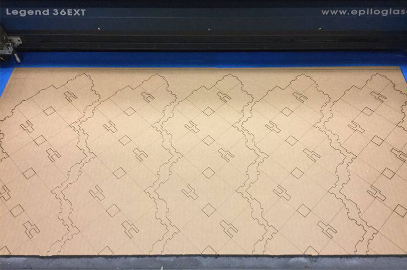
Figure 13. The final print at the Epilog Laser Cutter 60w.

Figure 14. The final cuts, aligned in both sides. Taping the cardboard and testing with the pointer helped the cutting process a lot.
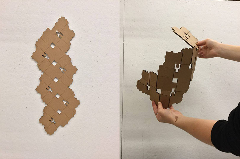
Figure 15. Starting to fold the flat net.