Maroula Bacharidou
MAS.863 | How to Make (Almost) Anything
Output devices
Making the hello.RGB.45 board, and redesigning it
*1. Assignment
2. Milling and soldering the hello.RGB.45 board
3. Redesigning the hello.RGB.45 board
*
1. Assignment
This week's assignment was to add an output device to a microcontroller board that we have designed and program it to do something. I decided to work with the RGB LED, however making some changes to the hello.RGB.45 board. The reason why I did this was that I would need a board with an RGB LED but more pins than those of the ATTiny 45. I used the old and beloved ATTiny 44a, as it had a lot of pins that I could use for my final board's connections with the sides of my bricks. What I would need for this board was a lot of free copper pads, or pins, to solder the wires that would connect them to the conductive pads of my bricks' surfaces. I solved this problem using ISPs - an easy-to-solder way to add pins to your board! I thought that I would need at least 4 + 3 = 7 pins for my final board (4 for the 4 sides plus a data, a + and a - pin). However, I used two 2X3 head ISP because I thought that when testing my boards I would probably need more cables = more pins.
2. Redesigning, milling and soldering the hello.RGB.45 board
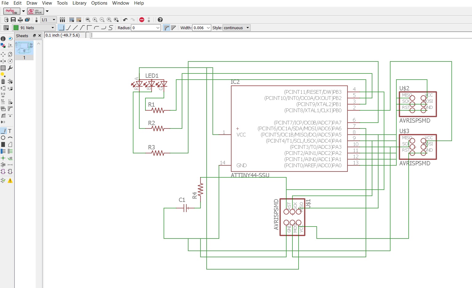
Figure 1. Collecting my board parts from fab-lbr in EAGLE and making my connections in the schematic mode.
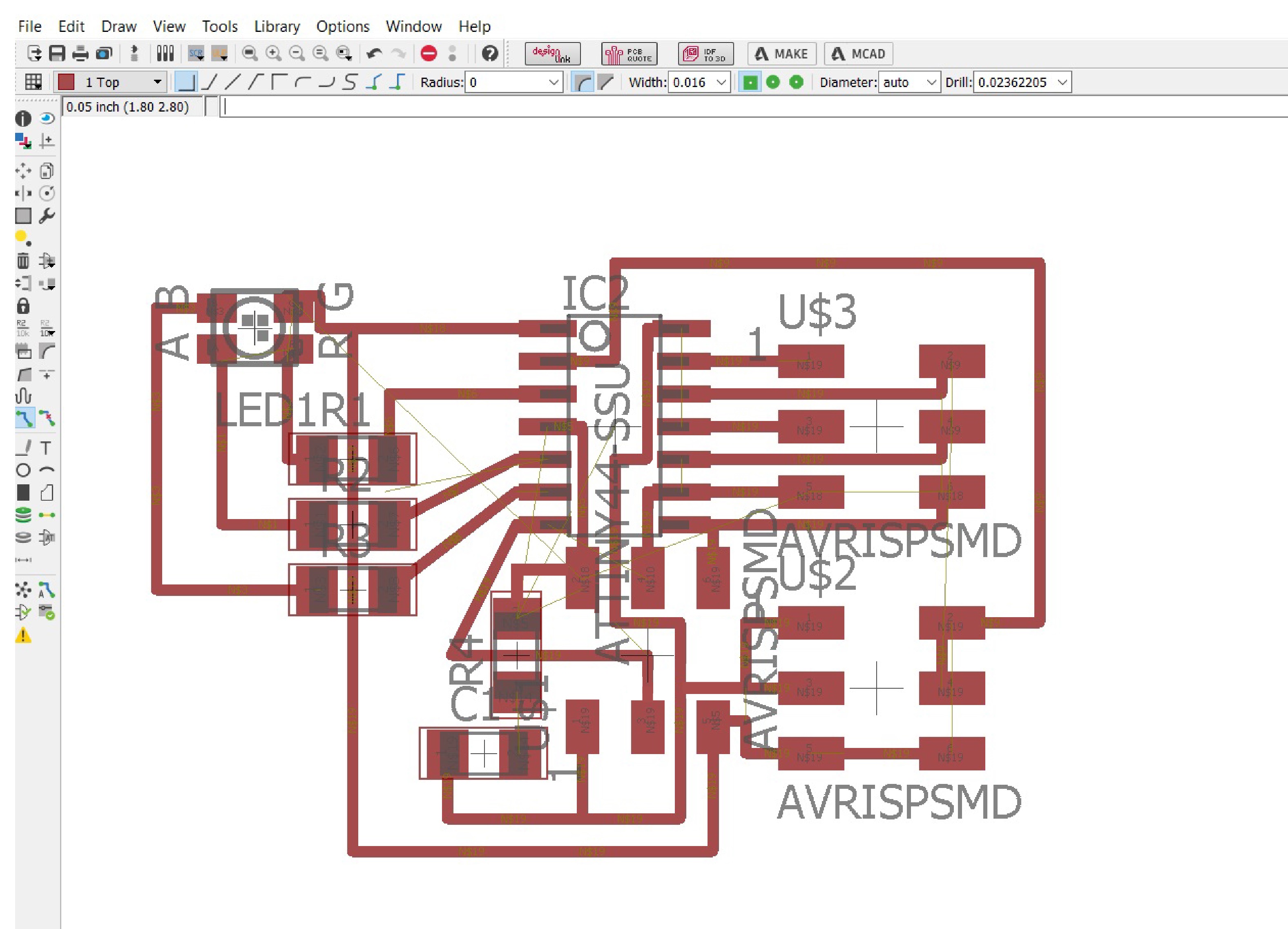
Figure 2. Routing was "tight" in some parts of the board, especially the one around the bottom ISP.
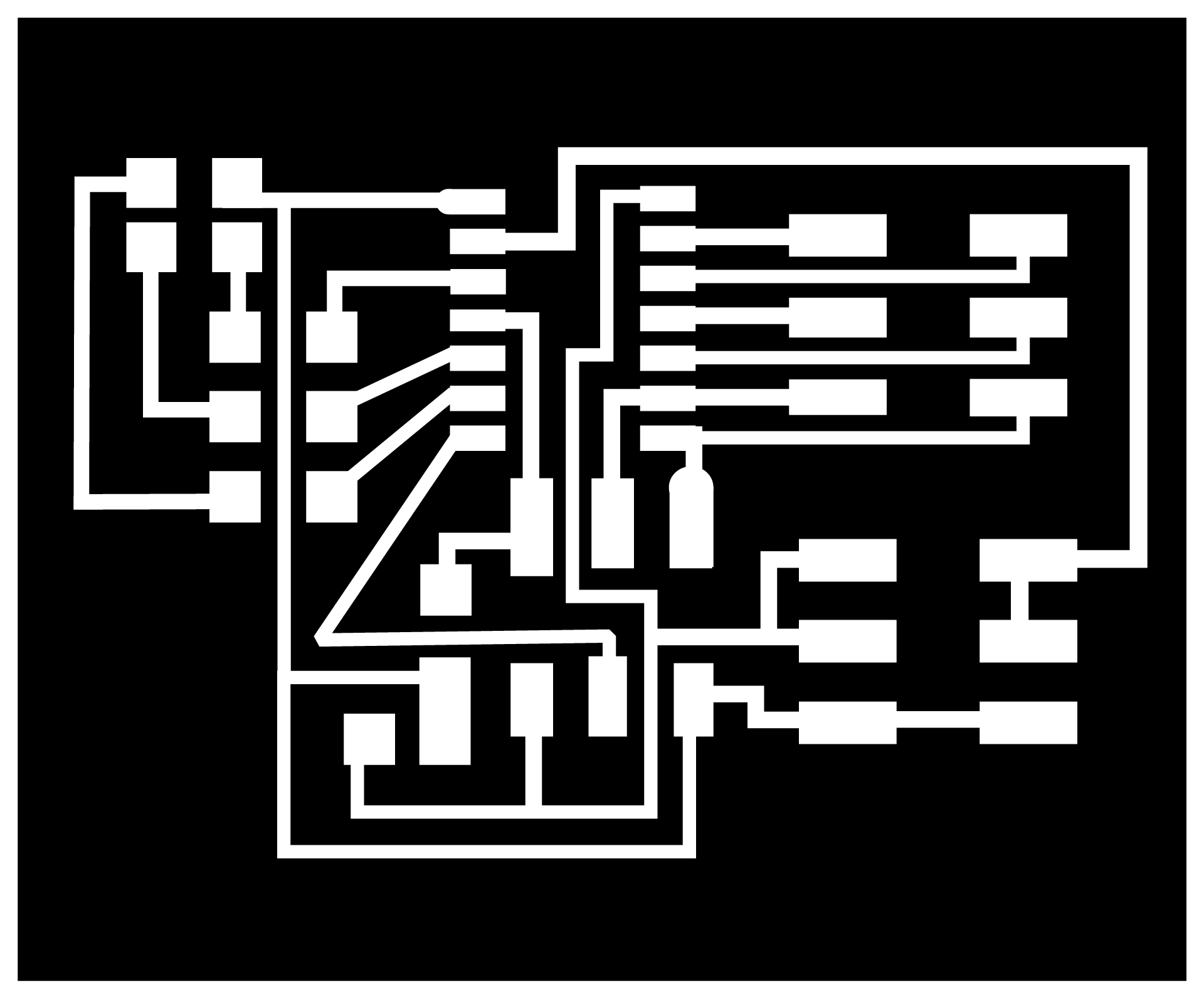
Figure 3. The final design of my board.
*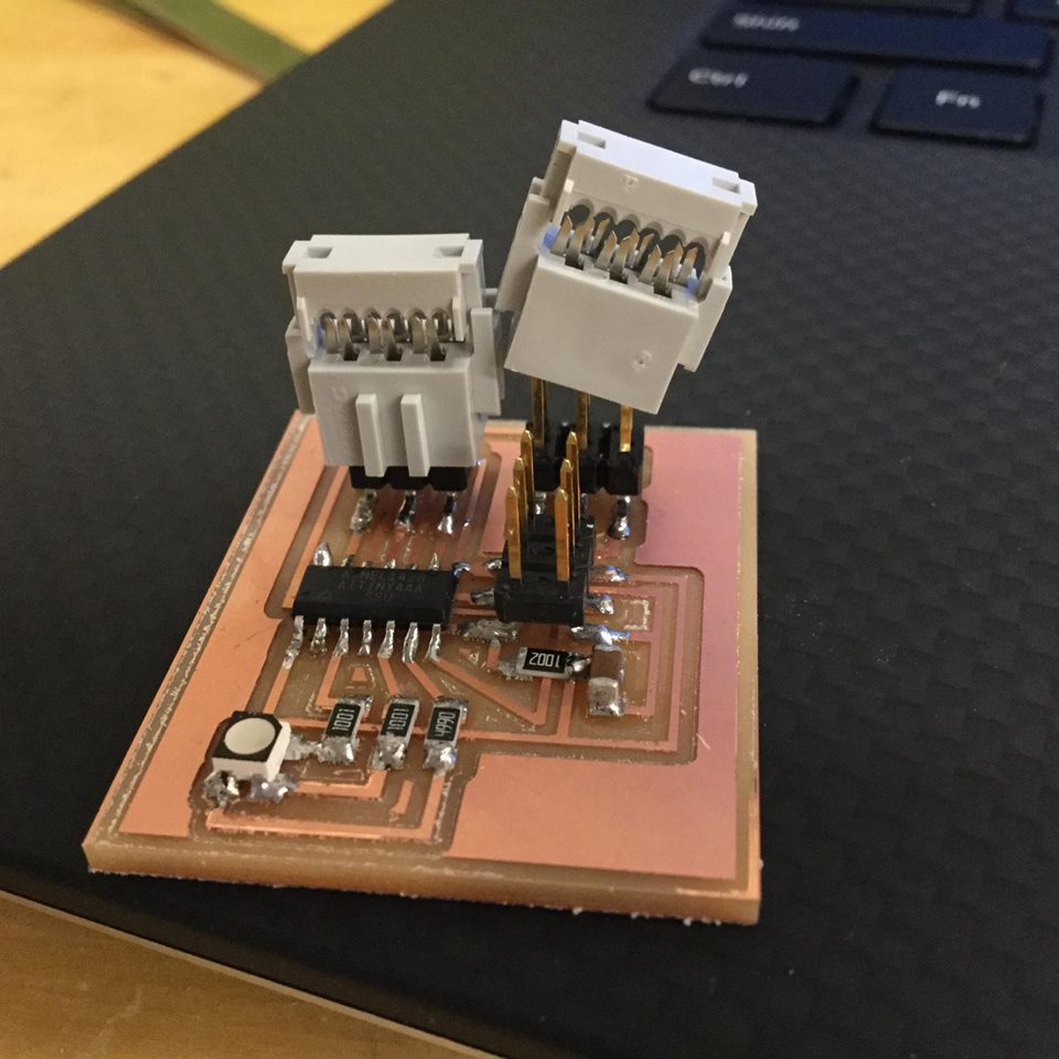
Figure 4. The moment you realize that you have designed a board to fit two ISPs and the rainbow cable holders of the two ISPs don't fit on your board.
4. Programming
I programmed my board using Arduino and running Neil's code:
void setup() {
  // put your setup code here, to run once:

}

void loop() {
  // put your main code here, to run repeatedly:

}


//
//
// hello.RGB.45.c
//
// RGB LED software PWM hello-world
//
// Neil Gershenfeld
// 11/10/10
//
// (c) Massachusetts Institute of Technology 2010
// This work may be reproduced, modified, distributed,
// performed, and displayed for any purpose. Copyright is
// retained and must be preserved. The work is provided
// as is; no warranty is provided, and users accept all
// liability.
//

// #include <avr/io.h>
// #include <util/delay.h>

#define output(directions,pin) (directions |= pin) // set port direction for output
#define set(port,pin) (port |= pin) // set port pin
#define clear(port,pin) (port &= (~pin)) // clear port pin
#define pin_test(pins,pin) (pins & pin) // test for port pin
#define bit_test(byte,bit) (byte & (1 << bit)) // test for bit set
#define PWM_delay() _delay_us(25) // PWM delay

#define led_port PORTB
#define led_direction DDRB
#define red (1 << PB1)
#define green (1 << PB0)
#define blue (1 << PB2)

int main(void) {
   //
   // main
   //
   unsigned char count, pwm;
   //
   // set clock divider to /1
   //
   CLKPR = (1 << CLKPCE);
   CLKPR = (0 << CLKPS3) | (0 << CLKPS2) | (0 << CLKPS1) | (0 << CLKPS0);
   //
   // initialize LED pins
   //
   set(led_port, red);
   output(led_direction, red);
   set(led_port, green);
   output(led_direction, green);
   set(led_port, blue);
   output(led_direction, blue);
   //
   // main loop
   //
   while (1) {
      //
      // off -> red
      //
      for (count = 0; count < 255; ++count) {
         clear(led_port,red);
         for (pwm = count; pwm < 255; ++pwm)
            PWM_delay();
         set(led_port,red);
         for (pwm = 0; pwm < count; ++pwm)
            PWM_delay();
         }
      //
      // red -> green
      //
      for (count = 0; count < 255; ++count) {
         set(led_port,red);
         clear(led_port,green);
         for (pwm = count; pwm < 255; ++pwm)
            PWM_delay();
         clear(led_port,red);
         set(led_port,green);
         for (pwm = 0; pwm < count; ++pwm)
            PWM_delay();
         }
      //
      // green -> blue
      //
      for (count = 0; count < 255; ++count) {
         set(led_port,green);
         clear(led_port,blue);
         for (pwm = count; pwm < 255; ++pwm)
            PWM_delay();
         clear(led_port,green);
         set(led_port,blue);
         for (pwm = 0; pwm < count; ++pwm)
            PWM_delay();
         }
      //
      // blue -> on
      //
      for (count = 0; count < 255; ++count) {
         set(led_port,blue);
         clear(led_port,green);
         clear(led_port,red);
         for (pwm = count; pwm < 255; ++pwm)
            PWM_delay();
         set(led_port,blue);
         set(led_port,green);
         set(led_port,red);
         for (pwm = 0; pwm < count; ++pwm)
            PWM_delay();
         }

      //
      // on -> off
      //
      for (count = 0; count < 255; ++count) {
         set(led_port,blue);
         set(led_port,green);
         set(led_port,red);
         for (pwm = count; pwm < 255; ++pwm)
            PWM_delay();
         clear(led_port,blue);
         clear(led_port,green);
         clear(led_port,red);
         for (pwm = 0; pwm < count; ++pwm)
            PWM_delay();
         }
      }
   }