Networking and communications
Overview
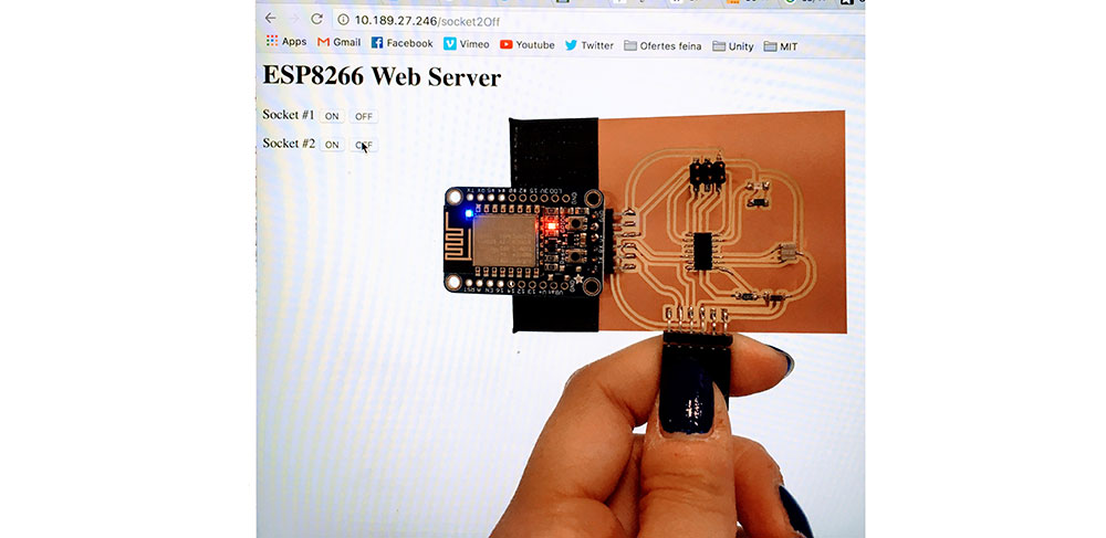
- We are asked to design and build a wired &/or wireless network connecting at least two processors. I used an ESP8266 from Adafruit and decided to make a simple board with an LED that would turn on when sending a value.
Board
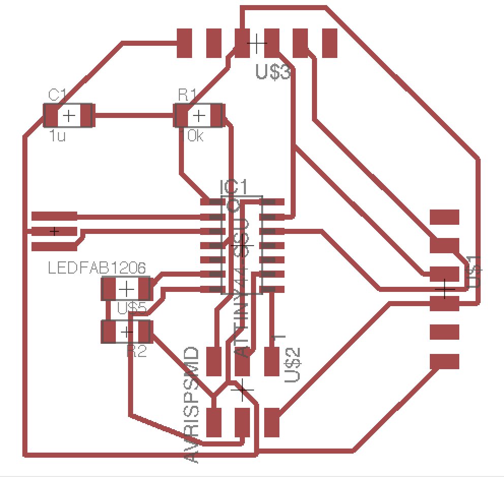
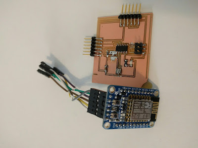
- I designed my board with headers to connect the ESP8266. I was a simple attiny44 board with 2 more considerations:
- We need to connect the TX pin from the ESP8266 to the RX pin of the Attiny44 in order to send the information we receive via wifi to the microcontroller.
- We also have to connect the TX and RX pins from the ESP8266 to the FTDI connecting to the computer in order to be able to program the ESP8266 and get values from it to debug.
Components
- Attiny44 Microcontroller
- ESP8266 Wifi Module Adafruit
- LED
- 1k Resistor
- 10k Pull-up Resistor
- 1uF Capacitor
- Resonator
- Header 2x3 SMD
- FTDI Header x 2 [One for Usb serial and one for Wifi module] .
Programming
-
I used the hello.ftdi.44.echo.c to test the circuit and just have a simple led light blinking. Next, I followed these instructions to install the ESP8266. I used this tuorial to setup an ESP8266 Web Server with Arduino IDE.
I wrote code for the wifi module to send an 'r' everytime we press the button on the website. You may see the code here
Sending over information
-
Open a browser and type the IP address followed by the arguments of the script, and press buttons on the website to light the LED.