Final Project Updates
Resources
- Embedded programming resources
- AVR 8 microcontrollers: https://startingelectronics.org/tutorials/AVR-8-microcontrollers/
- ATtiny2313 Tutorial Introduction: https://startingelectronics.org/tutorials/AVR-8-microcontrollers/ATtiny2313-tutorial/
- Starting AVR 8-bit Development: https://startingelectronics.org/tutorials/AVR-8-microcontrollers/starting-AVR-development
- Battery
- Microcontroller
- ATmega32U4 vs ATmega328P: http://grantukropina.com/archives/82
- Sparkfun ATmega 32u4: https://learn.sparkfun.com/tutorials/arduino-comparison-guide/atmega32u4-boards
- Atmel microcontrollers comparison: http://www.atmel.com/products/microcontrollers/avr/megaavr.aspx
- Arduino companions (Leonardo/Uno , Atmega32u4/Atmega328P): https://www.arduino.cc/en/Products/Compare
- Connectivity
Planning
I am making a Musical Rubik’s cube, and there are 3 key areas of development involved:
- Circuit Design
- Input devices
- I need 6 rotary encoders I used in my input devices week [link to input devices week]
- each encoder needs 2 input pins so I need a total of 12 input pins and ATtiny doesn’t have enough
- Output devices
- Microcontrollers
- Battery
- Connectivity
- Input devices
- Programming
- Input logic
- Output logic
- Setting up the pins on the board
- 3D printing and mechanical design
- 3D design
- 3D printing
- Assembly
Spiral development milestones
- Input and output devices
- Get some input from one rotary encoder - using Arduino Yun [Programming]
- Get accurate turning values from rotary encoder - using Arduino Yun [Programming]
- Hook up 6 rotary encoders and read turns using Arduino Yun [Programming]
- Attach a speaker and play sounds based on turns [Programming]
- Fit inside the rubies’ cube
- Replace the Yun with Micro or your own micro controller - ask Neil’s permission for former
- Design the rubies’ cube so that the Micro, speakers and encoders fit inside
- Create a hole space for wire to power the circuit
- Battery considerations
- Design your own micro controller to replace the micro - ask Neil if Micro is fine
- Fit battery inside the rubik’s cube
- Connectivity
- Use Arduino feather or your own board
Detailed notes
- Concept
I decided to make a musical Rubik’s cube - one that plays musical notes when you turn different sides. I knew from the beginning that this was going to be a mechanically challenging project because Rubik’s cube has a tough design and to fit the electronics inside the cube was not going to be easy. - Input devices
I did lots of brainstorming on how to detect Rubik’s cube turns. There are several possible options including computer vision or using a robotics arm to turn the Rubik’s cube so we know which turns are being made. However, I wanted an approach that needed no additional robots or computers, just a programmable Rubik’s cube so I looked around what electronics I could use to detect turns. My options were a potentiometer or a quadrature encoder (rotary encoder). The benefit of a rotary encoder over a potentiometer is that a rotary encoder can be turned infinitely. So, my rotary encoder became my choice of input device. The remaining question was how I was going to fit the rotary encoder inside the center cubies of the Rubik’s cube. I had 2 options in mind:- Center cubie with a pole and the encoder could be inserted inside the pole.
- Center cubie with a hole so that the encoder could be inserted in the hole.
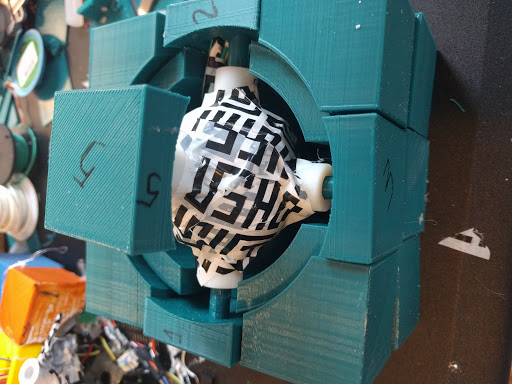
In both case, when the center cubie turned, the shaft of the rotary encoder turned as well and thus, Rubik’s cube rotations were detected. The choice between 1 and 2 depended on the shaft length of the rotary encoder and the relative size of the cube. I ended up choosing the first option because the shaft size was small compared to the pole length required to connect the center cubie to the inner center piece of the Rubik’s cube.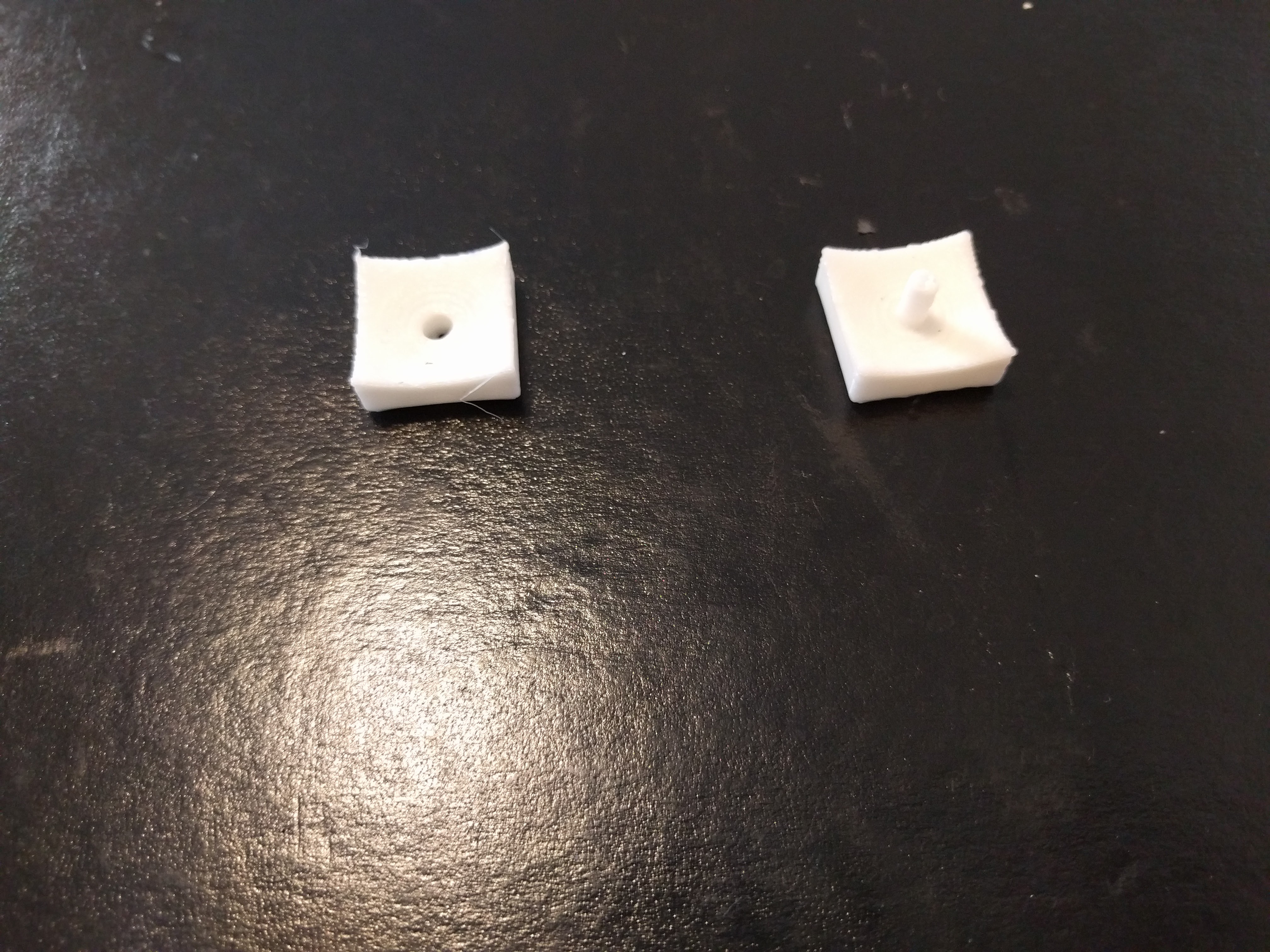
A rotary encoder needs connections to 2 input pins and one ground pin on the microcontroller. You can read more about how rotary encoder works in my Input page. During my input devices week, I made a simple circuit to detect turns of a rotary encoder. Then I fit those rotary encoders inside my Rubik's cube.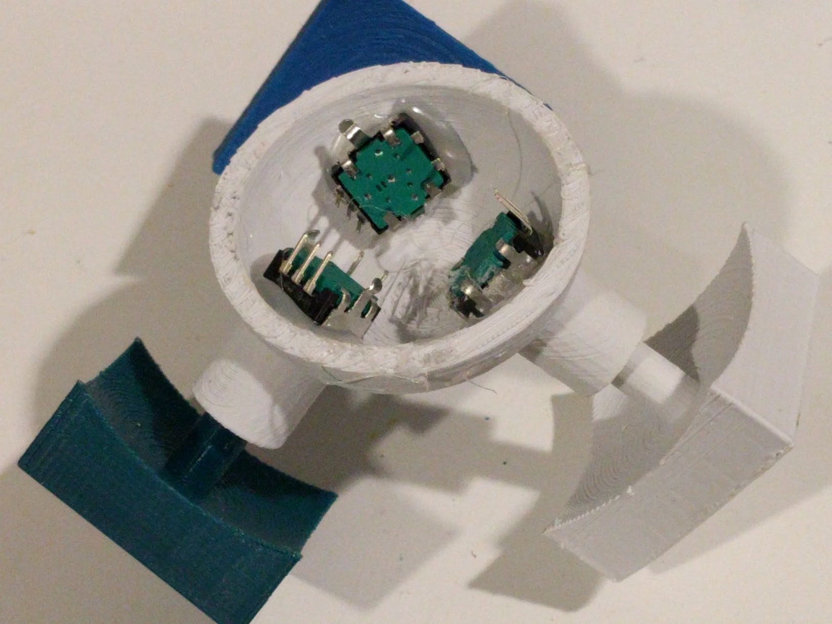
- Output devices
Since I was doing a musical Rubik’s cube, my choice of an output device was pretty obvious, i.e. a speaker. A speaker has very simple connection: one to ground and another to a digital pin.- I tried 2 speakers:
- Mini piezo speaker
- Speaker with 3-inch diameter
- Microcontroller
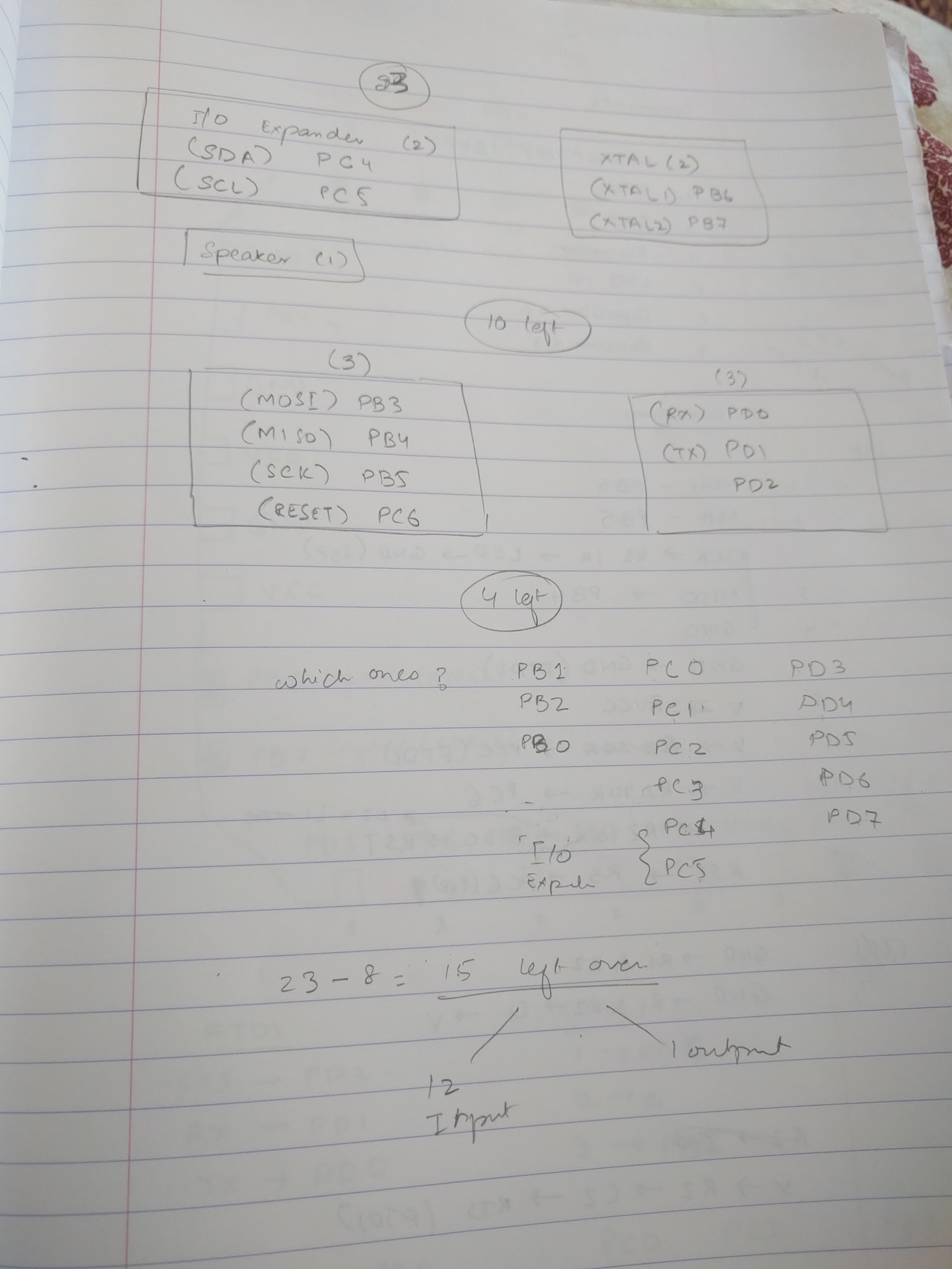
Based on my input choice, i.e. 6 rotary encoders, each of which needed at least 2 input pins, I needed at least 2*6+1 = 13 I/O pins (12 input pins and 1 for speaker). This meant that I couldn’t use the ATTINY24/44/84 as they have only 12 I/O pins. Among the 20 I/O boards, I was deciding between ATMEGA328P and ATMEGA32u4. ATMEGA328P doesn’t natively support USB and I was going to use ATMEGA32u4 but the ATMEGA 328P was available in the shop and so I decided to go for those. Luckily, there was a pageon our class website about using ATMEGA328P, which was very helpful. - Battery Power
I went through different phases when it comes to powering the device. I thought that the best option would be if the Rubik’s cube ran on rechargeable batteries enclosed inside the Rubik’s cube. Best case scenario would be wireless charging. I thought maybe I would enclose a small battery inside the Rubik’s cube with the electronics, but then I realized that that scenario would mean that I had no access the Rubik’s cube circuitry once the Rubik’s cube was assembles and that was a huge bet for a first prototype. So I kept the battery issue for much later in the process until I had fitted the circuitry (excluding the battery) inside the Rubik’s cube. I thought I would then decide if there was pace for battery.
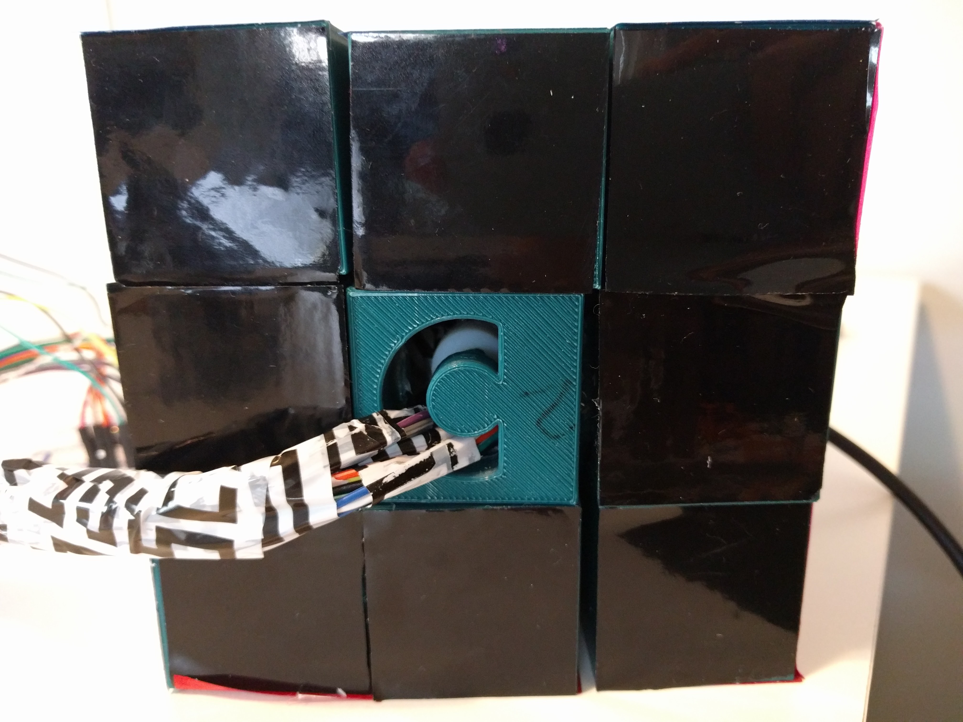
I decided that I needed a way to debug the circuit even after the Rubik’s cube was fully assembled. So I created a rectangular opening inside the Rubik’s cube’s inner center and in one of the center cubies so that my FTDI to USB wire could be attached from inside of the Rubik’s cube to my computer for debugging. I soon realized that I could use the FTDI cable for powering my circuit and thus stopped worrying about the battery because my first prototype needed the FTDI cable anyway for debugging. And thus, there was no extra cost in using it to power the circuit too. - Wiring
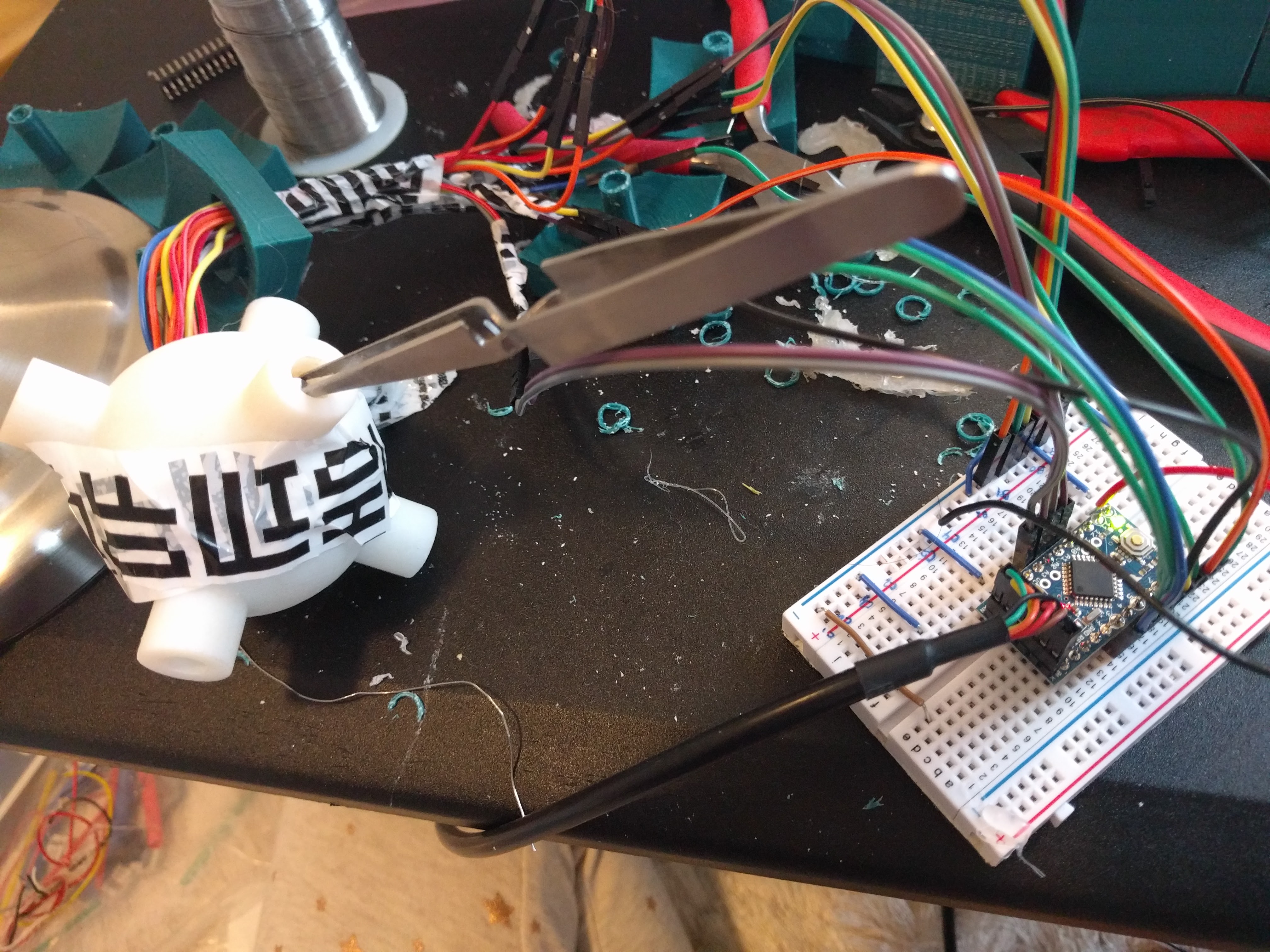
Usually when we’re designing, we do not have to worry about our wires taking up much physical space in the final project because the wires are part of the PCB when the input devices are surface mounted. But in my case, the input devices were spread over the surface of the spherical inside of the Rubik’s cube and thus, had to be attached to the board using wires that were floating above the board. It’d have been cool to have the circuit printed on the spherical surface of the inside of the Rubik’s cube, but that was a bit too much for me so close to the deadline.
The wires took up a lot of space as there were 3 for each encoder so 3*6=18 wires. I cut the wires really short and they barely fit inside my spherical center, which had an inner diameter of about 2 inches. Since the wires occupied the entire inside of the spherical cube of my Rubik’s cube, I had to improvise because that was where my PCB and speaker were supposed to go.
The rectangular cut that I had made inside my Rubik’s cube inner center and center cubie then came in handy. Instead of passing my FTDI cable through the cut out, I used this cut out as a way out for my wires from the rotary encoders.. I moved the PCB circuit outside the spherical center and connected the wires from the rotary encoders inside the circuit through the rectangular cut out to the PCB outside the center.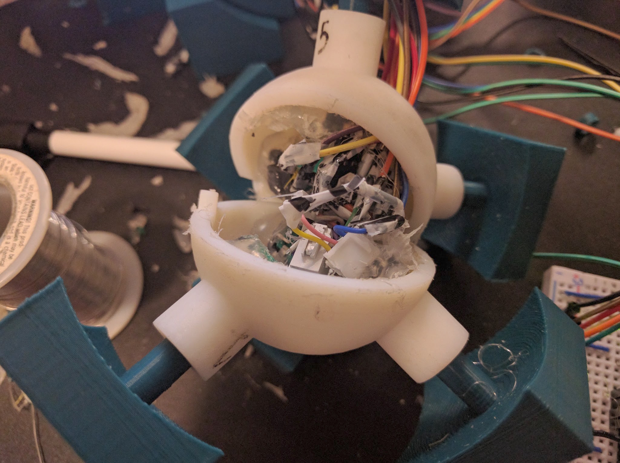
One benefit of moving the circuit outside the Rubik’s cube was that I wasn’t confined by the 2 inch diameter of the Rubik’s cube and the only PCB that could fit inside the 2 inch center was a very small circuit board, e.g. a Arduino Pro Mini or Micro. Any circuit that I made with 13 I/O pins and other components, had to be double sided or multi-layered to fit all the components in a circuit board of with each dimension less than 2 inches.
I could have also increased the size of the Rubik’s cube to fit a bigger board, but a Rubik’s cube with ~2 inch center is ~4.5 inches cube, which is relatively big compared to normal sizes of a Rubik’s cube (~2 inches). Als, increasing the size of a Rubik’s cube also increased the printing time, chances of the print job failing, and the cost of the cube. The current cube already need 60 hours of printing.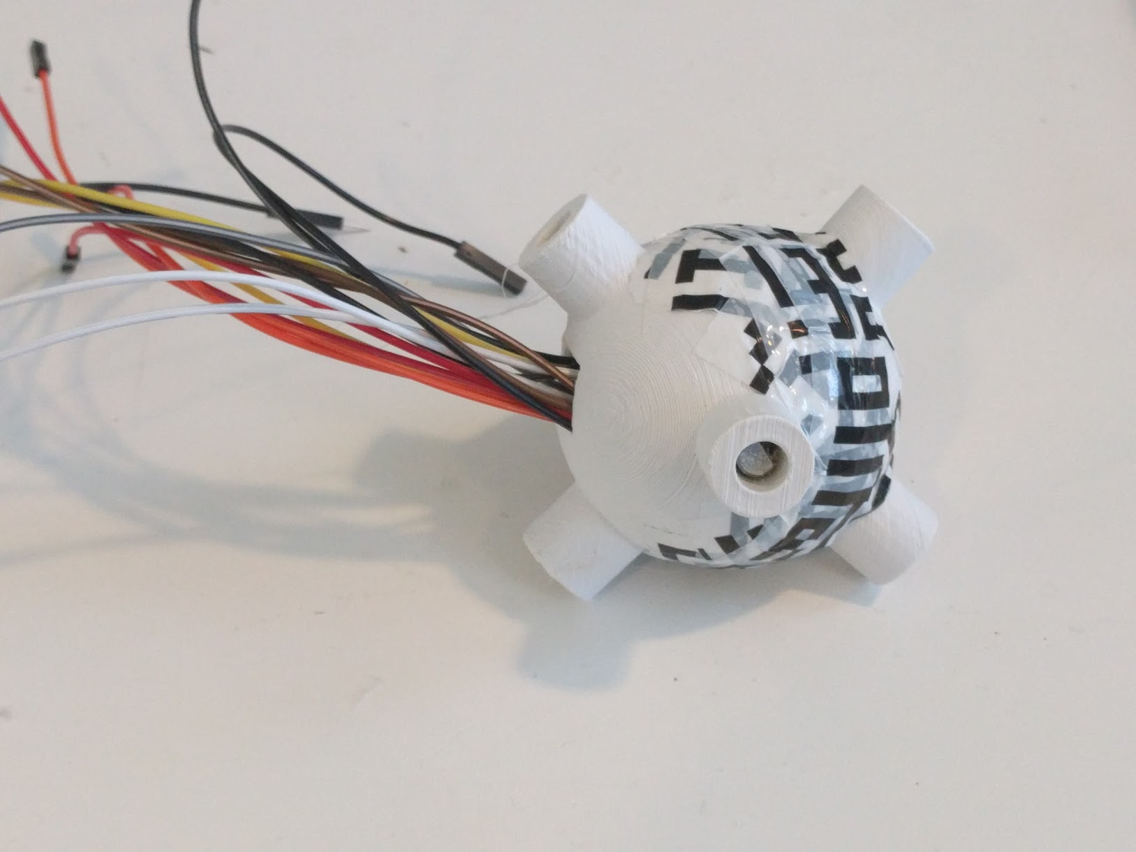
Thus, with all the considerations mentioned above, I ended up with a 4.5 inche Rubik’s cube with a circuit board outside neatly connected to the rotary encoder pins inside the cube.
- Modeling the Rubik’s cube
Modeling the Rubik’s cube was harder than one would think because a Rubik’s cube has no screws or any additional parts to join the moving cubies. Thus, the cubies and the center should not only fit together neatly but also move in different directions. I am glad I started the process of thinking about the design of a Rubik’s cube during the 3D printing week because I did not just have to reproduce the design of a Rubik’s cube, but also modify it so that I could fit the rotary encoders and the circuitry inside the rubik’s cube.
One of the most helpful things in the process was my choice of the tool. I decided to go with FreeCAD, which allows for parametric design (unlike Rhino without Grasshopper) and has a really nice visualization (unlike Antimony, which is parametric, but does have a really good visualizations).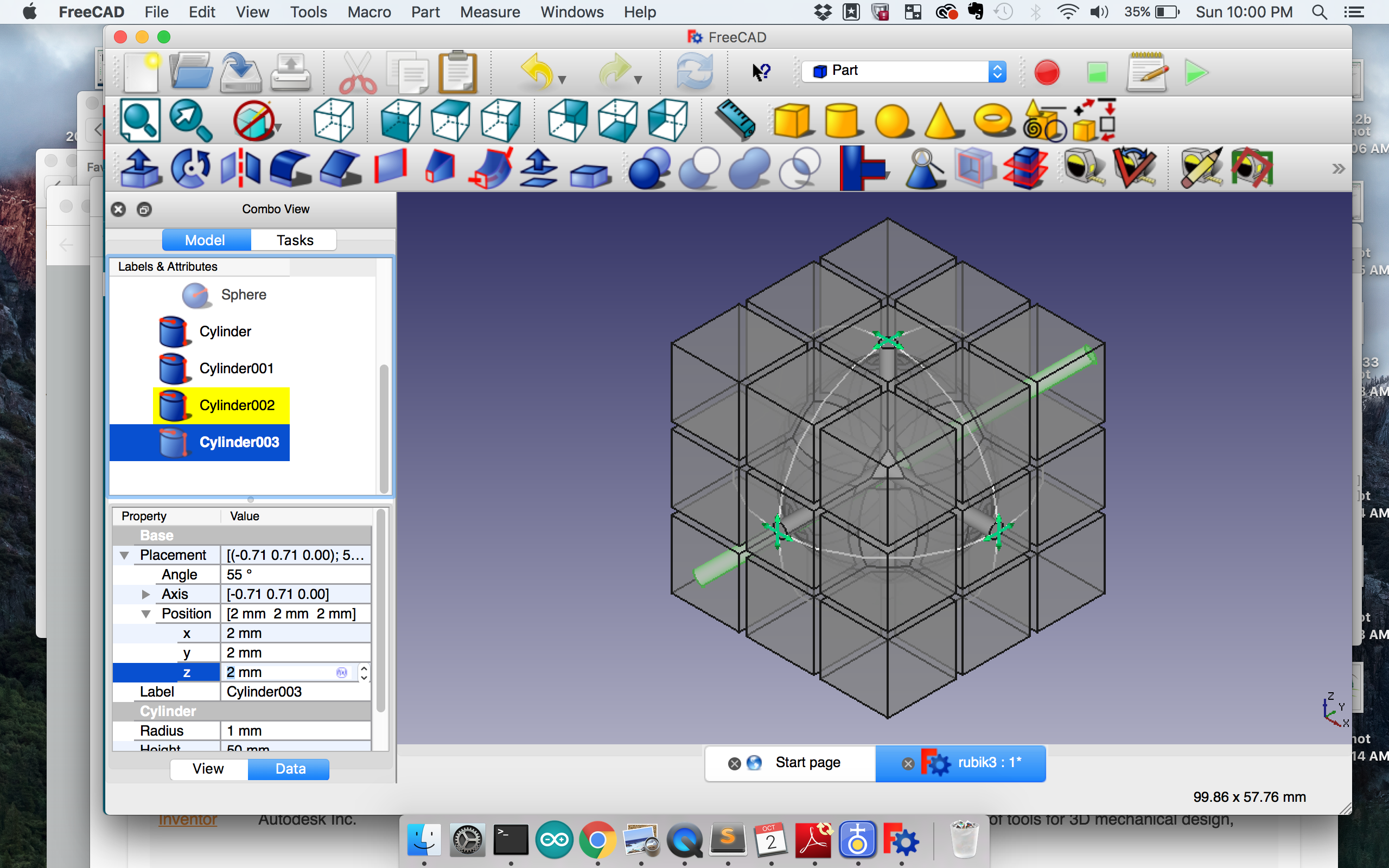 FreeCAD also has tools for splitting a cut object into 2 separate pieces. First, cut the piece using the Part workbench, and then Downgrade suing the Draft workbench. I heavily relied on this feature and I heard one of my friends complaining about how this splitting feature was not available in Fusion360 (I didn’t check if it was).
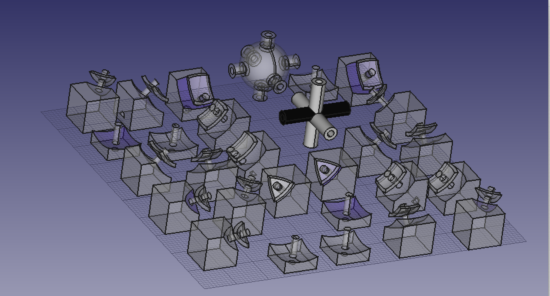
So my first steps to understand the design of a Rubik’s cube was to break open my Rubik’s cube and reverse engineer what was going on. I noticed that each corner and edge cubie had parts extending from the main cube into the other cube so they could be locked with the neighbouring parts. The corner cubie interlocked with 3 othe edge cubies and the edge cubie interlocks with either 2 edge cubies (center layer) or 2 corner cubies (top and bottom layer). But I wondered what was about this design that made it work. After viewing several images of the inside of a Rubik’s cube, I realized that the interlocking parts pieces of a spherical shell in the center with 2 cuts along each of the x, y, and z axis slightly offset from the cuts of the cubies from the cube. This understanding allowed me to design my Rubik’s cube by using cuts, intersections, splits, and unions between cylinders, spheres, and cubes.
There was one more element in the design of my cube, i.e. the inner center sphere. Normally, a Rubik’s cube would have a solid center . However, I had to fit my circuitry inside the Rubik’s cube and thus, had to cut my center sphere in half so that I could fit my circuitry and the join the two pieces of the sphere later. I had 2 versions of the cut.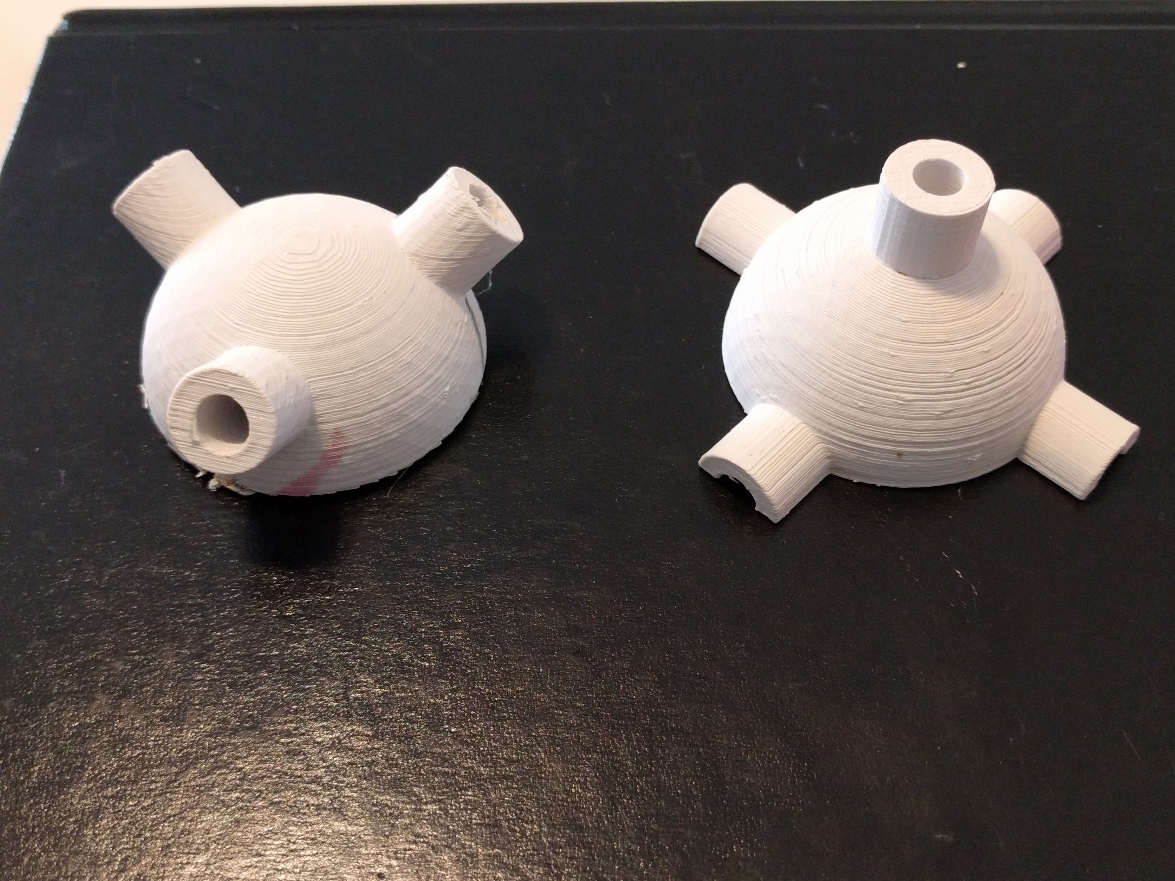
- Cut along the xy-plane that intersected the cylindrical shells of the center where the center cubies connected to the center. This was not good as I noticed later because while joining the 2 cut halves of the cylindrical shells, it was very likely that I would glue the encoders and prevent the encoders from turning. Also, gluing the halves of cylindrical shells meant that the diameter of the cylindrical shell could be variable because of the glue. This was a big risk because the center cubies had to fit snugly inside the cylindrical shells.
- A cut with a plane rotated about 60 degrees along the x and z axis. This avoided cutting the cylindrical shells to avoid the problems in 1, and was my final choice. Since the cut was titled, it was relatively hard to assemble as I didn’t know exactly the right way to put the two parts together. So I eye-balled my first print to join the two halves, but in my next one, I added a notch to know how the two parts aligned.
- 3D printing
I could have chosen different techniques for manufacturing my cubies for the Rubik’s cube. Molding and casting came to my mind because there was a lot of repetition for each of the 3 cubies - 6 center cubies, 8 corner cubies, and 12 edge cubies. However, it was difficult to make a mold for my pieces because there were 3D objects with undercuts. Update: Friday 16th, I realized that I could make molds, especially with the modified design of the rubik’s cube. This is great because I can make the cubies fasters and at lower costs. However, I am happy that I started with 3D printing for prototyping because it was easy to modify the scale and designs, and reprint, instead of printing mols over and over again. I think once I lock the sizes and designs of the Rubik’s cube parts, molding and casting would be the way to go. I asked Tom to put a Rubik’s cube for me, but he printed a 3cm by 3cm one , which was even smaller than my PCB so there was no chance that my circuit was going to fit inside! When I told him about my size requirements, he said that I’d have to use another printer because a 4.5 inch cube would cost thousands of dollars of material. The good part about the model that Tom printed was that I could see that all pieces were correctly designed.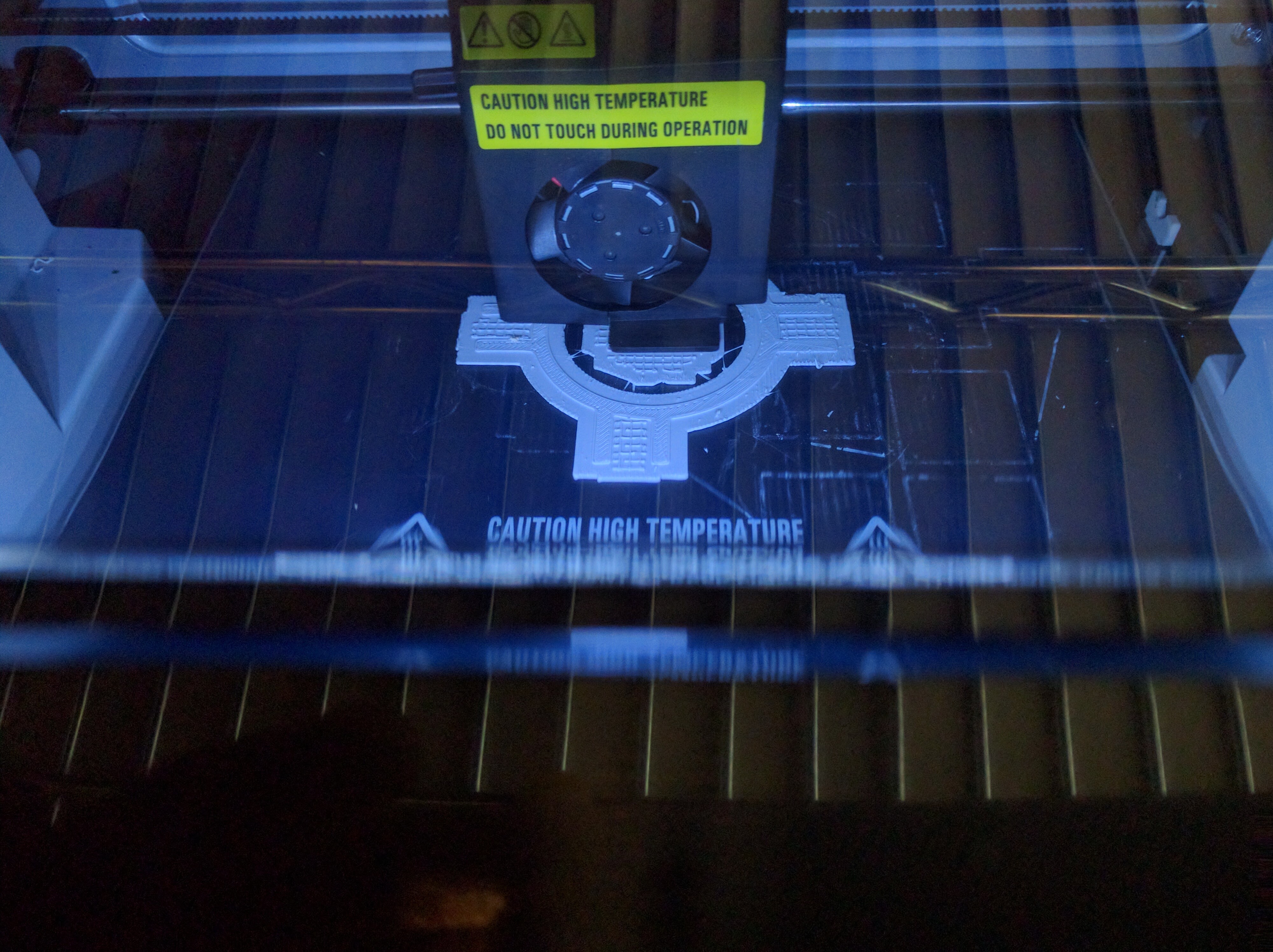
I did a next slightly larger print using PLA on 3DWox. The parts came out super nice and fit together. This cube was about 2.3 inches. My next and final print was a 4.5 inches cube.Iw worked well, except for the corner cubies. The corner cubies have a shape which you can visualize as a triangle projected on a spherical surface. When I scaled up the 3D print, the 3D printer could not do the pointed vertices of the corner cubie properly. This was the part that interlocks with the other cubie and as I realized later, it made interlocking between my cubies really bad. I learned that 3D printing does not scale as predictable as one would hope. In fact, things may get worse when scaled up because my corner pieces were relatively fine when my cube was smaller. I think a more expensive printer that didn’t involve fused deposition modeling (FDM) would have done a better job at the pointed vertices.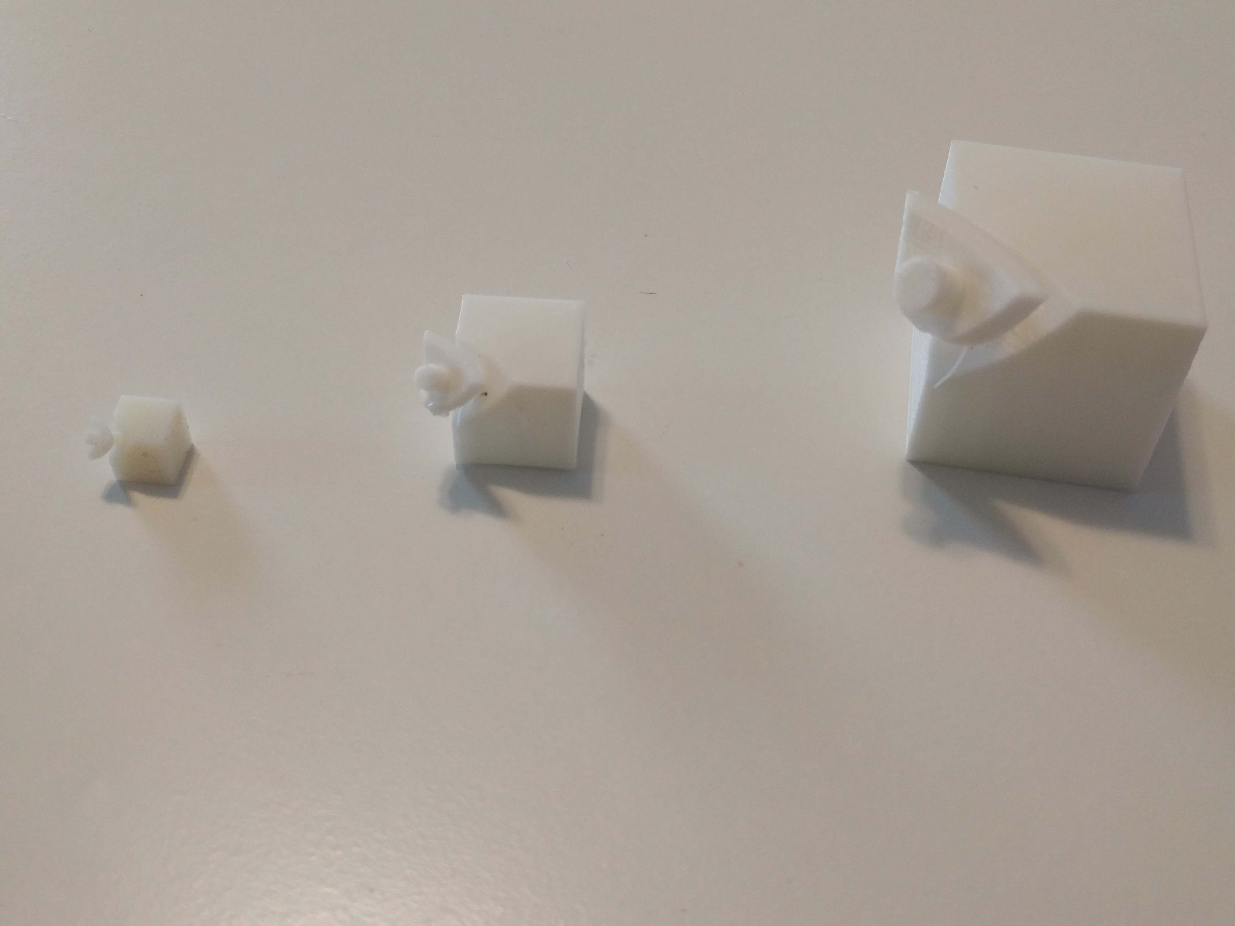
Update: The realized that the problem with the Rubik’s cube was not necessarily the broken vertices, but the thickness of the interlocking pieces attached to the cubies. The interlocking pieces had to be close to the cubie, where I had a thin interlocking piece connecting to the cubie with a cylindrical piece and therefore, the pieces kept falling apart.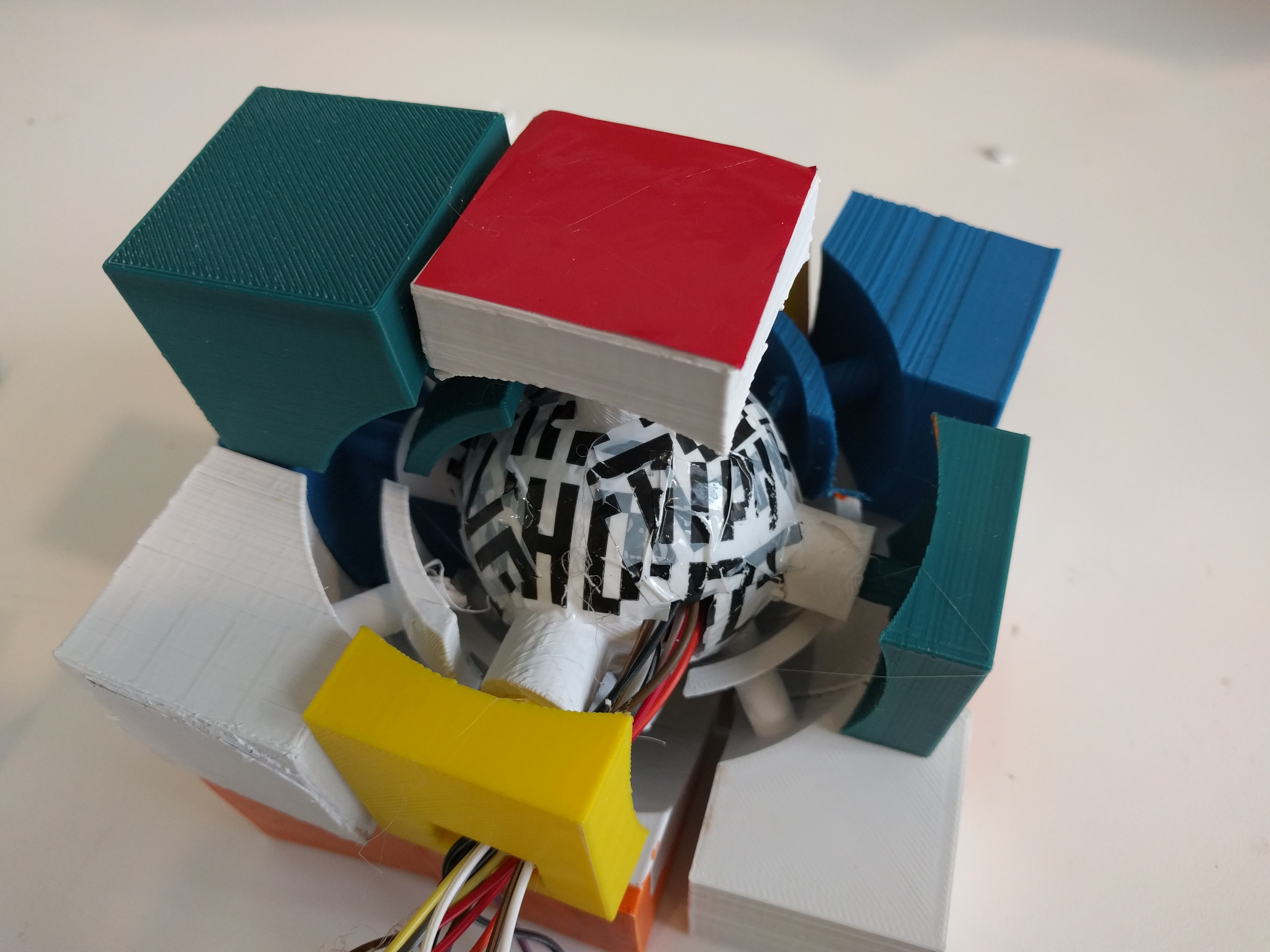

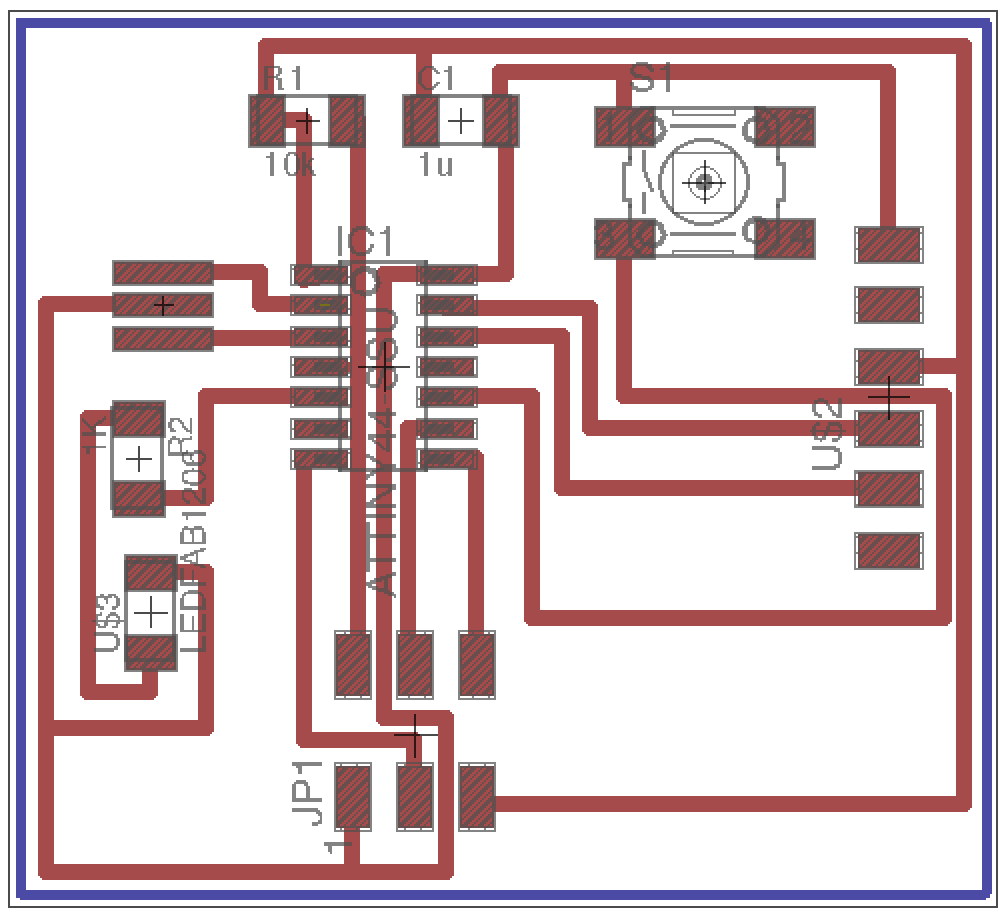
- PCB design
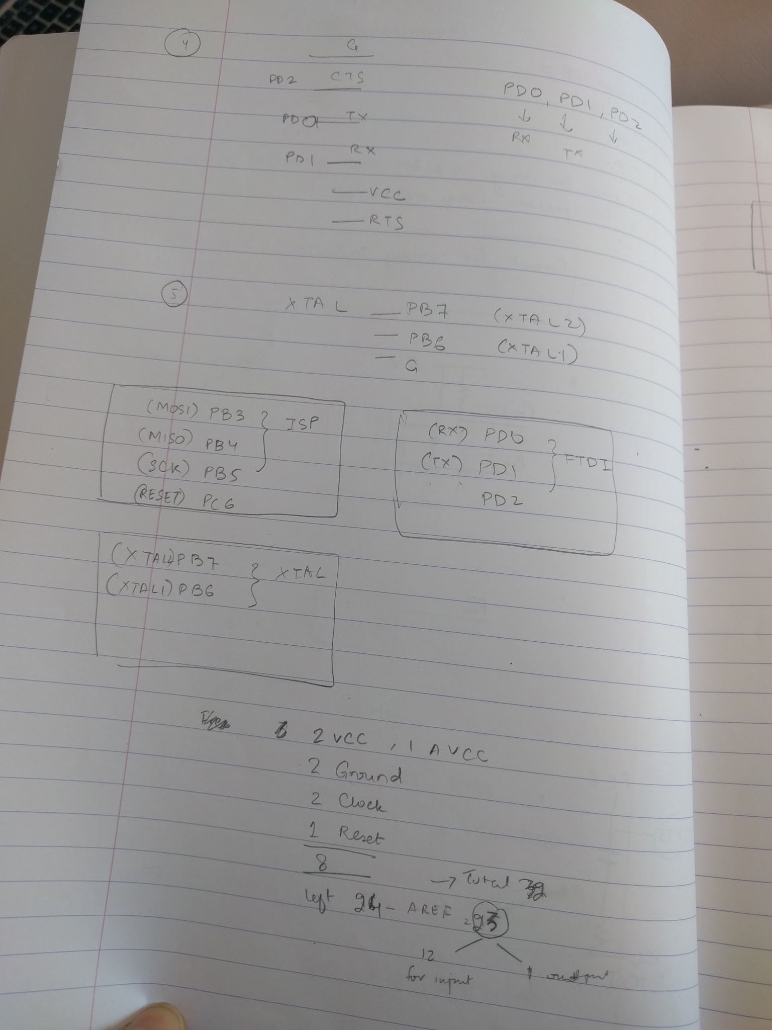
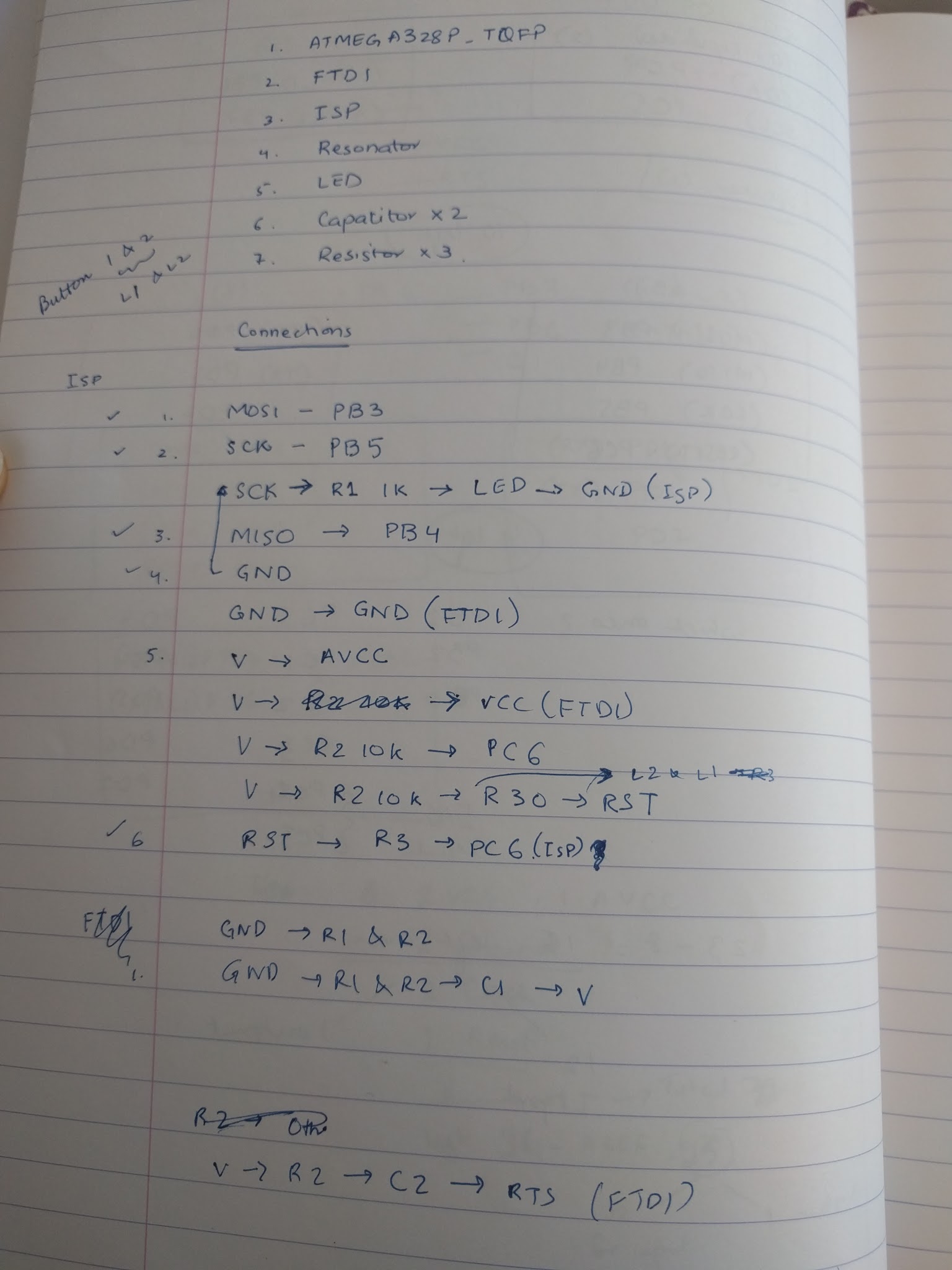
PCB design I was very scared of this step because I had limited circuit design experience and was especially new to circuit design with FTDI, SPI and microcontrollers. So, I took a step back and looked up what each of the components did and understood the purpose of each in a circuit.
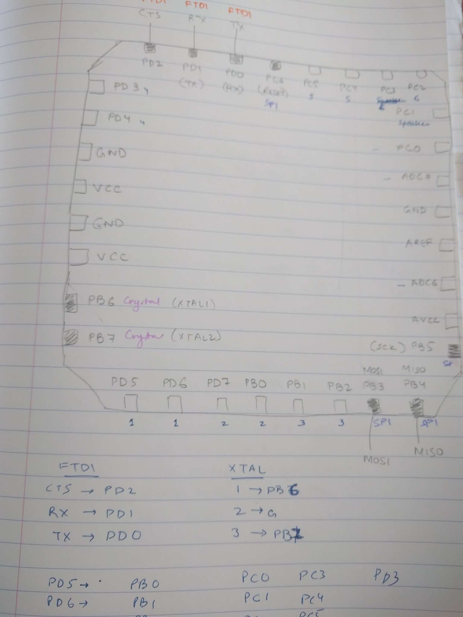
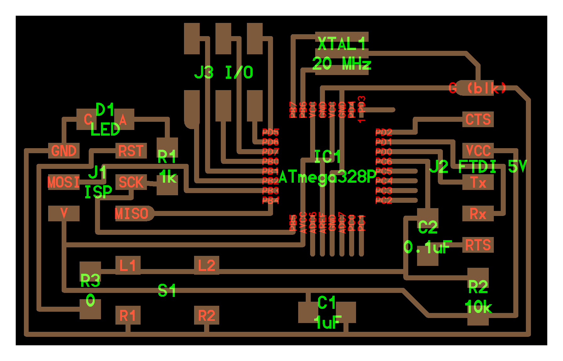
I looked at the schemas on sparkfun’s website and read the datasheet for 328P to understand the pin connections. After reading it for the 5th time, the pins start making sense. I also drew the chip so many times that I can almost draw the pins from memory now! Initially, I thought that I needed an I/O expander board but that was because I had miscounted the total pins as 23 instead of 32. After that I started design the board in eagle and exported it as a 600 dpi png that I halved in size before milling.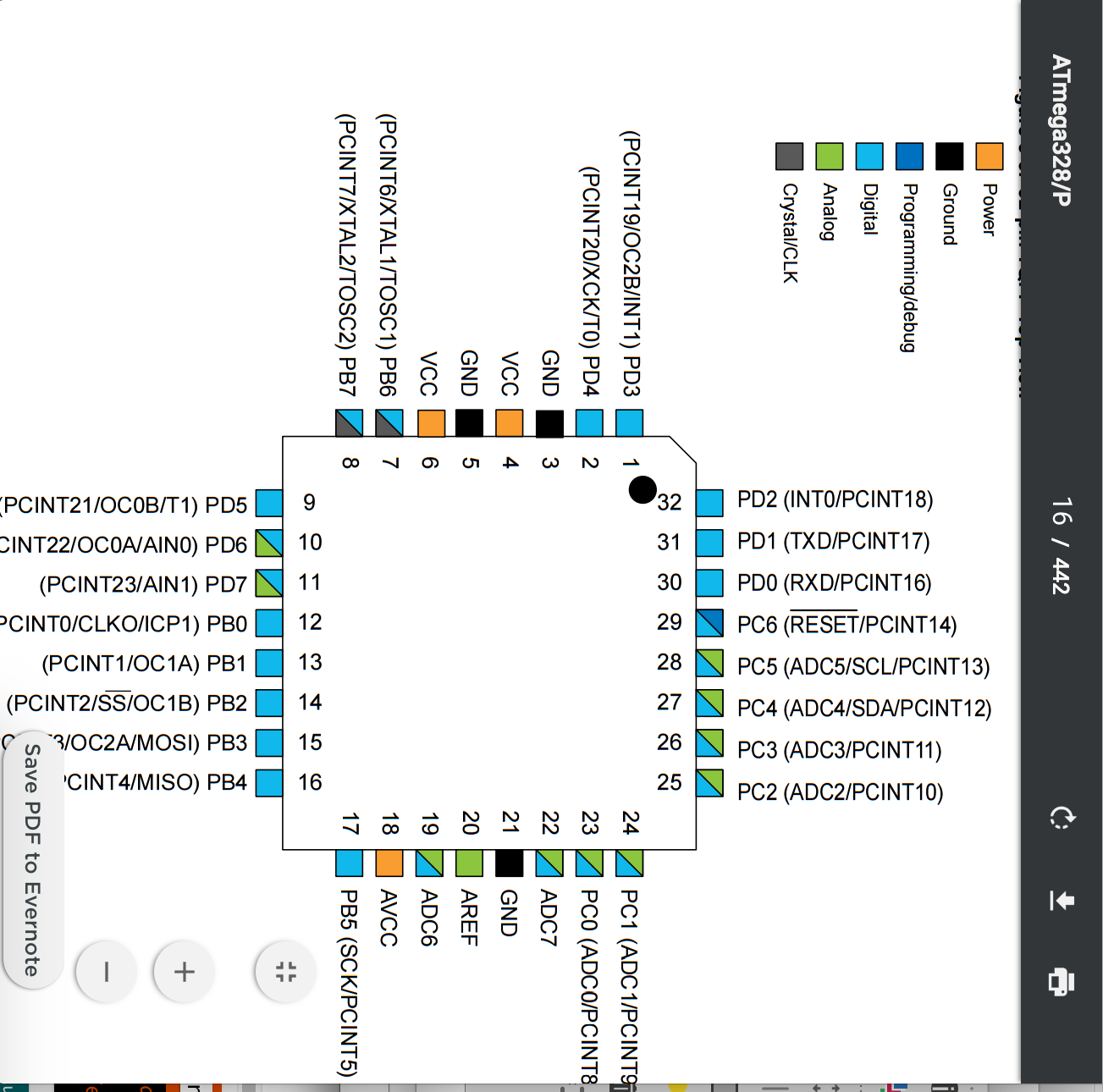
- Milling the board
My first board came out a little messed up but naively, I soldered the components without checking the connections. When I tried to run Neil’s blink program [[insert_link]] using the AVR programmer, the computer gave me error that the board was using too much power. I realized that it was because I had a short-circuit on my board.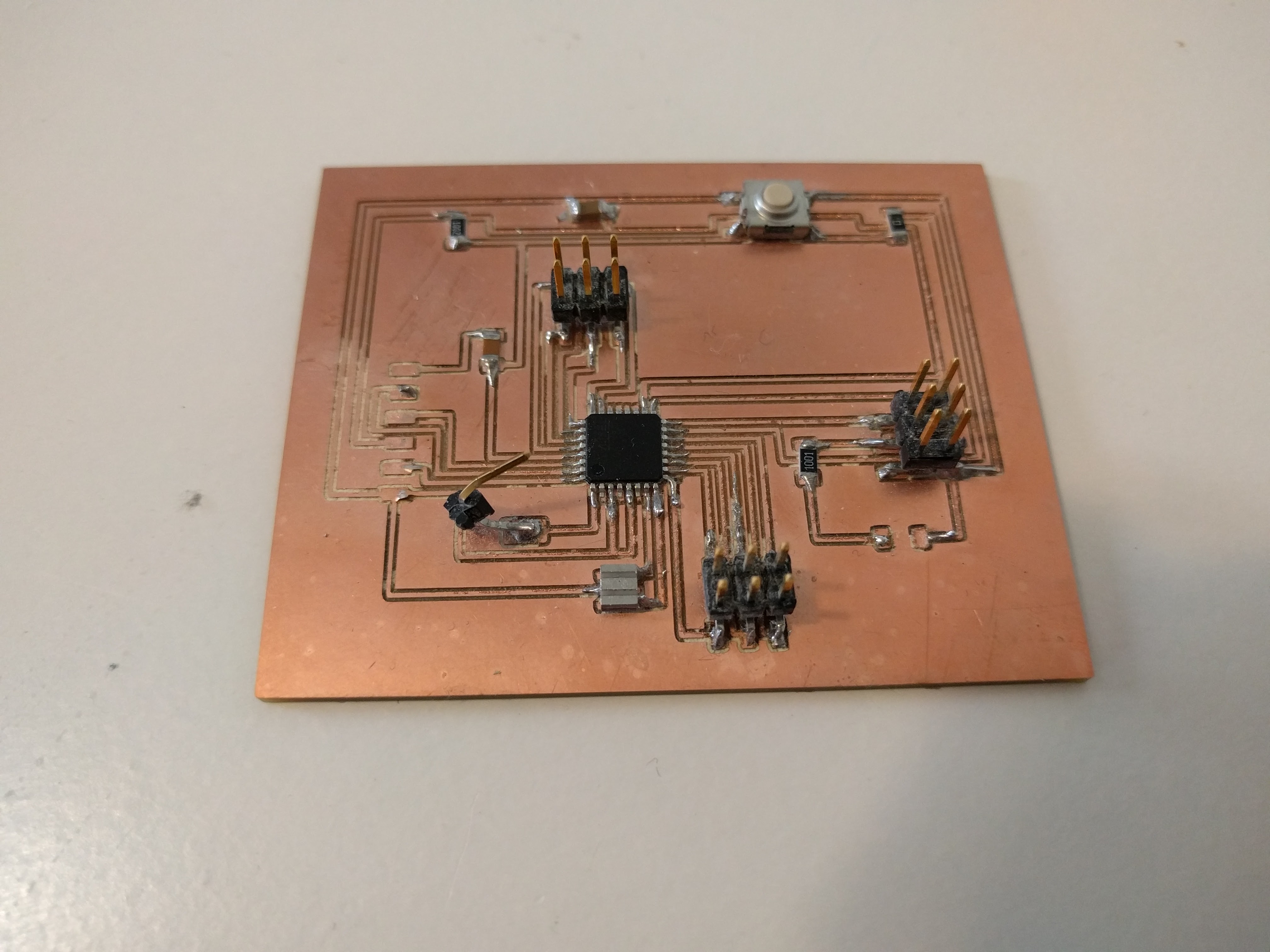
I then milled another board which came out much nicer. I first tested the connections on the board with a multimeter. Then I carefully soldered the components and checked the connections again, and the board looked good to go. By testing each step along the way, I made sure that if something went wrong, it wasn’t with the board.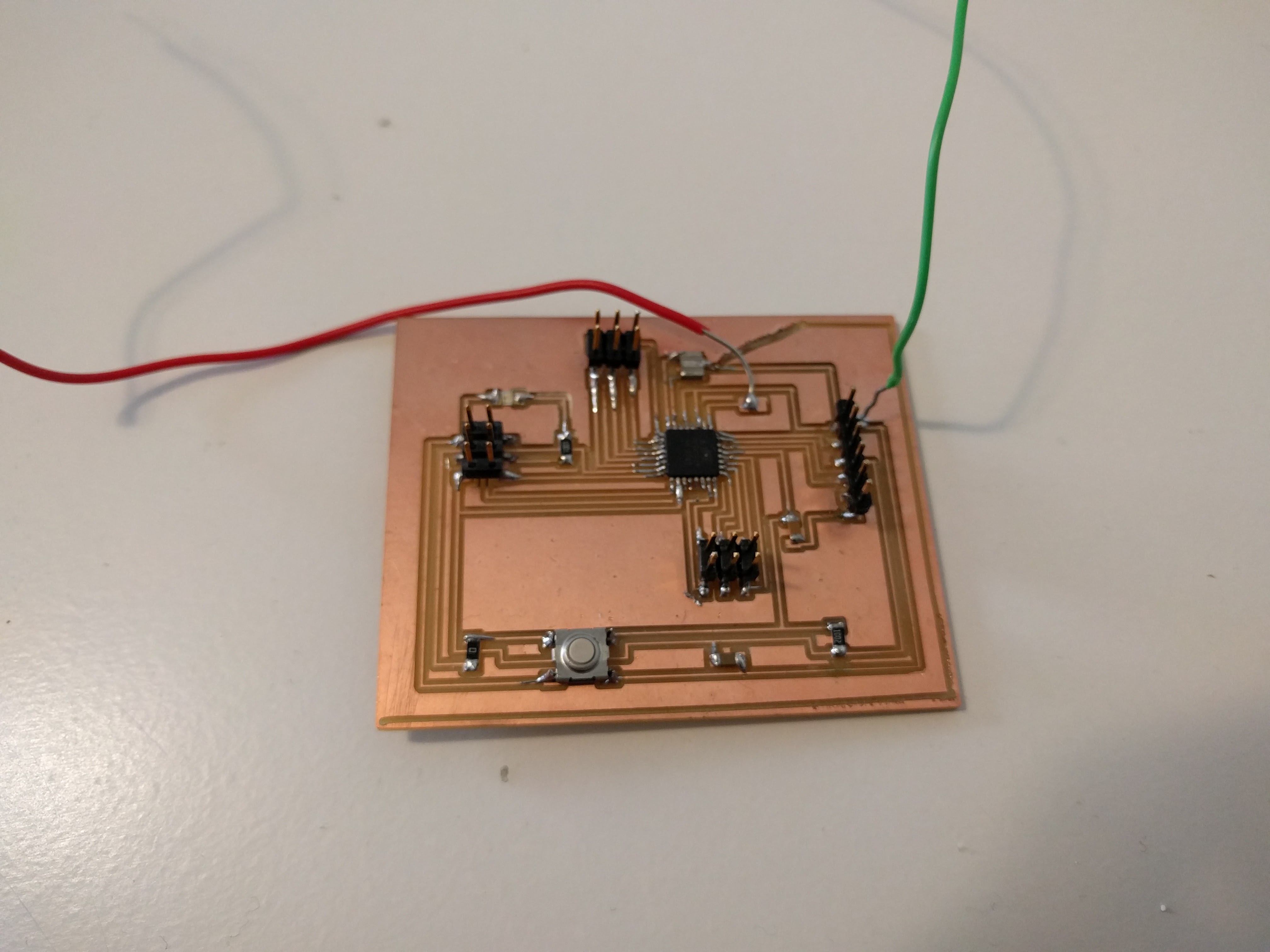
- Programming the board
I thought that there was lot from our class that I didn’t understand when it came to embedded programming and I read the first 6 chapters of the book Make: AVR Programming to get a good handle on AVR programming. I’d highly recommend the book to future students.
I tried three different kinds of programmer: AVRISP, USB tiny programmer that we made in class, and AVR pocket programmer. Macs have weird issues with these programmers and I realized that the most predictable one for me was the AVR pocket programmer, which works exactly like the USB programmer we made in class.
I had lots of problems installing AVRdude, even though I followed all the instructions. This was because my USB drive wasn’t working and I had forgotten to install the FTDI drivers.
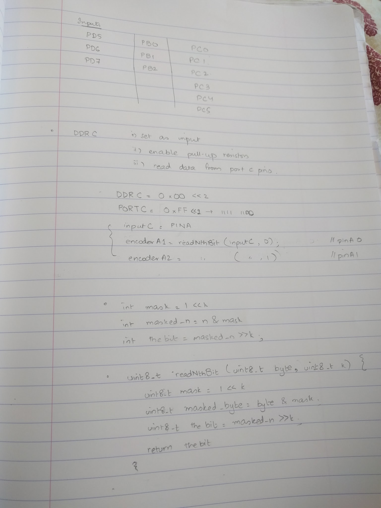
I used both the Arduino IDE and the terminal for uploading the program to the board, and I wrote my code for Arduino IDE (involving Arduino names for pins, e.g. 1, 2, etc) as well as the DDR style syntax.
You can see here how the pin names differ between arduino ide code and the code we upload without arduino ide.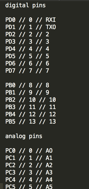
- Some final images
- Sketching the circuit