
Input devices
The component - Rotary or Quadrature encoder:
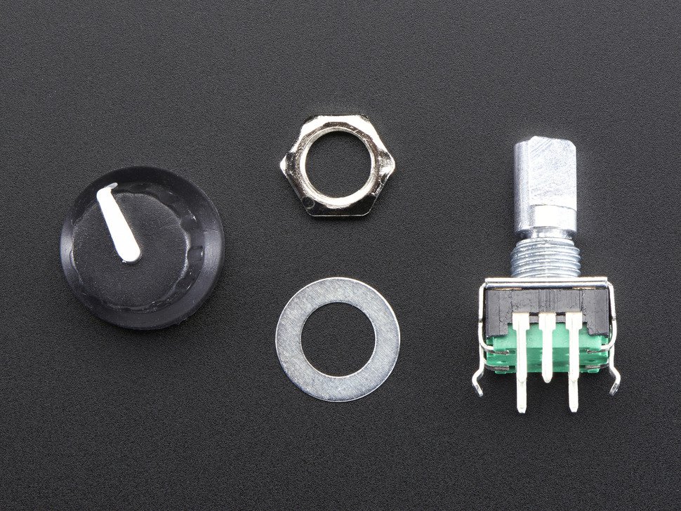
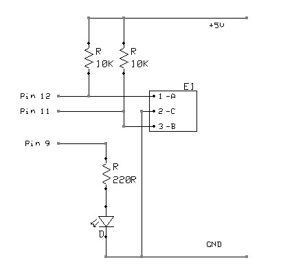
- 24-pulse and 24 segment rotary encoder from Adafruit to measure turning of Rubik's cube side. This is the component: https://www.adafruit.com/products/377
- Here's how Adafruit explains a rotary encoder:
A rotary or "shaft" encoder is an angular measuring device. It is used to precisely measure rotation of motors or to create wheel controllers (knobs) that can turn infinitely (with no end stop like a potentiometer has). Some of them are also equipped with a pushbutton when you press on the axis (like the ones used for navigation on many music controllers).
How does it work:
- Here's how Henry's bench explains the mechanisms of a rotary encoder:
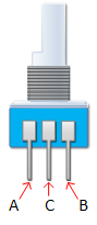
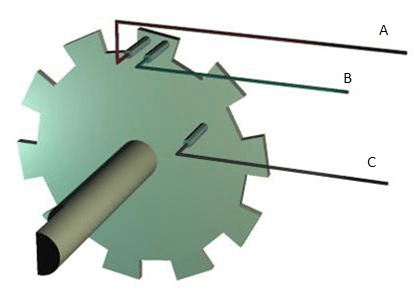
On one side of the switch there are three pins. They are normally referred to as A, B and C. Inside the encoder there are two switches. Once switch connects pin A to pin C and the other switch connects pin B to C. In each encoder position, both switches are either opened or closed. Each click causes these switches to change states as follows:
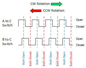
- If both switches are closed, turning the encoder either clockwise or counterclockwise one position will cause both switches to open
- If both switches are open, turning the encoder either clockwise or counterclockwise one position will cause both switches to close.
the angular position of the A terminal and the B terminal is such that:
- Rotating the switch clockwise will cause the switch connecting A and C to change states first.
- Rotating the switch counterclockwise will cause the switch connecting B and C to change states first.
Essentially, determining which switch changed states first is how the direction of rotation is determined. If A changed states first, the switch is rotating in a clockwise direction. If B changed states first, the switch is rotating in a counter clockwise direction.
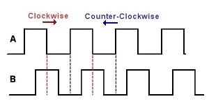
- Here's another explanation from Hobbytronics
With a rotary encoder we have two square wave outputs (A and B) which are 90 degrees out of phase with each other. The number of pulses or steps generated per complete turn varies.
Every time the A signal pulse goes from positive to zero, we read the value of the B pulse. We see that when the encoder is turned clockwise the B pulse is always positive. When the encoder is turned counter-clockwise the B pulse is negative. By testing both outputs with a microcontroller we can determine the direction of turn and by counting the number of A pulses how far it has turned. Indeed, we could go one stage further and count the frequency of the pulses to determine how fast it is being turned.
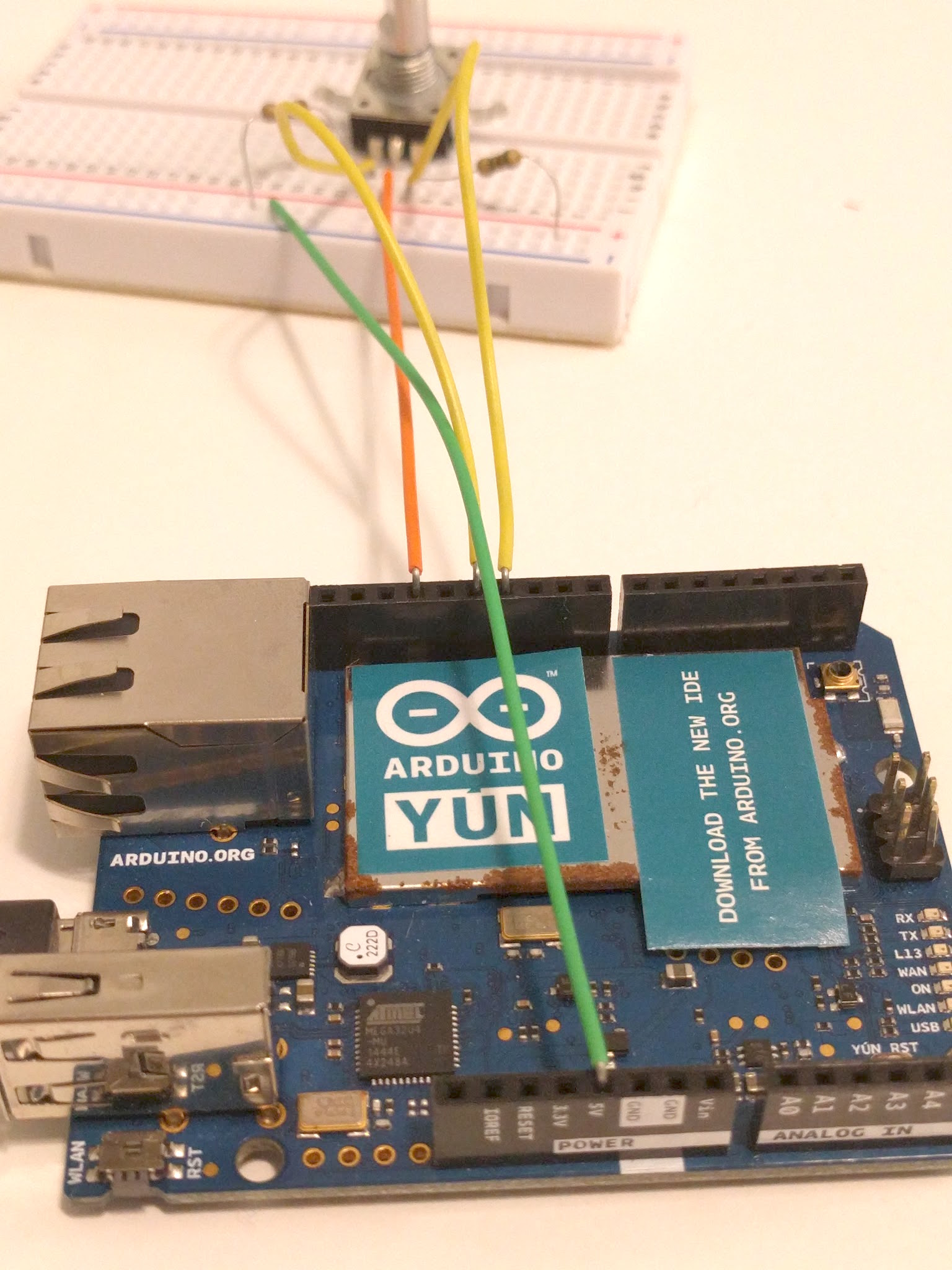
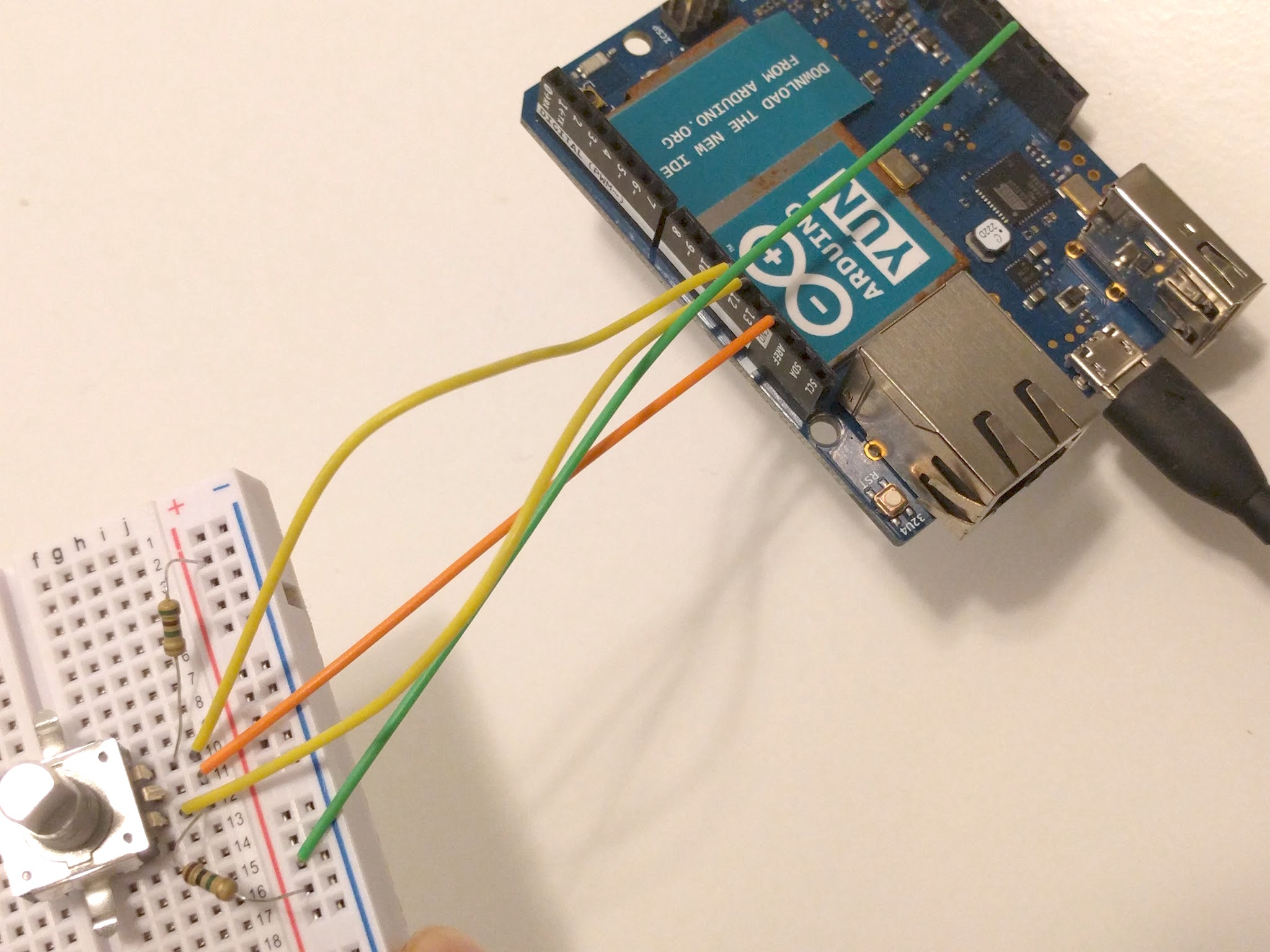
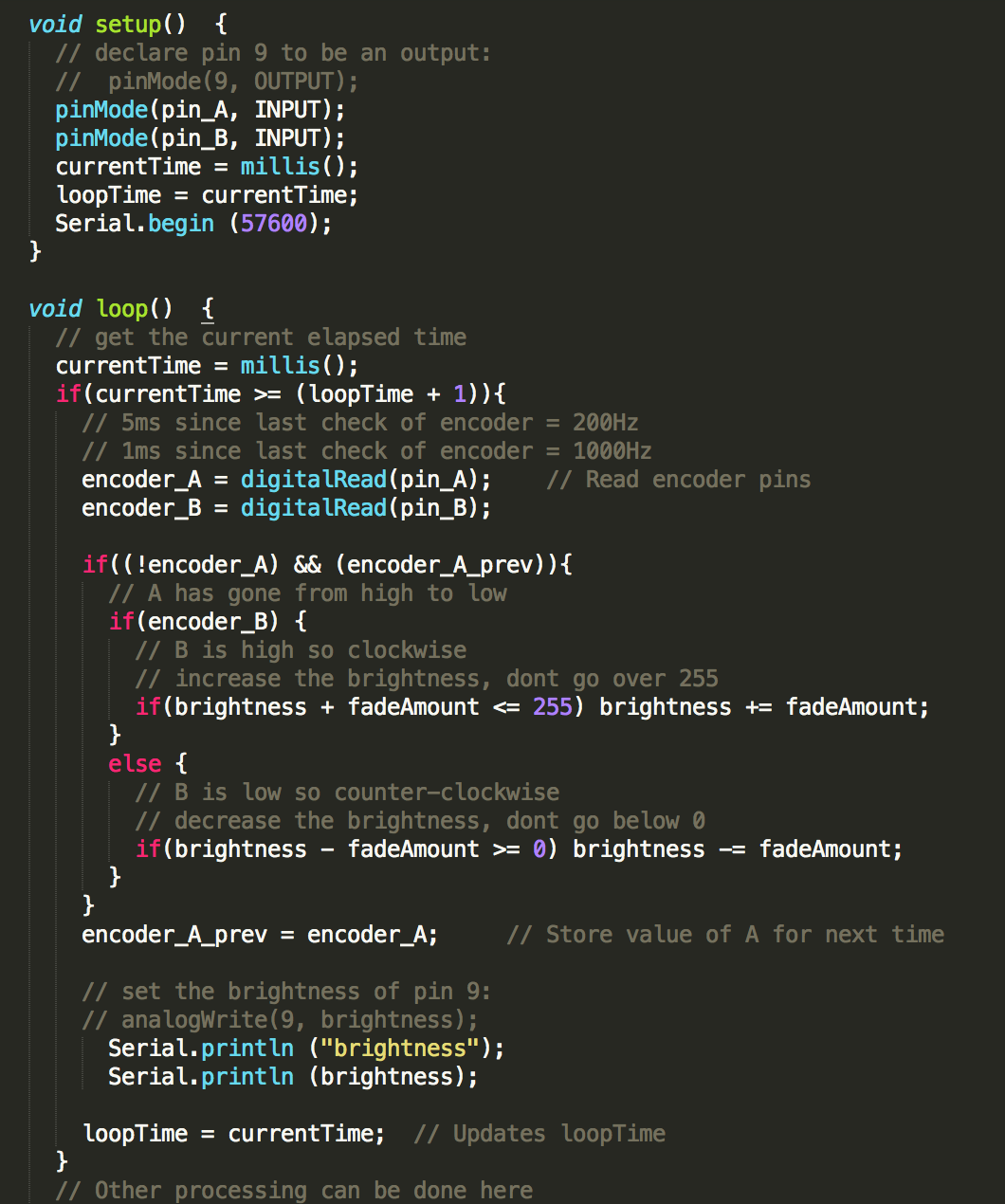
- Since I had never used a rotary encoder before, I didn't know how to design a circuit for it and milling the board would be a lot of wasted effort if things went wrong. Therefore, I decided to start testing the encoders using an Arduino. Initially, I did not connect pin A and pin C to the power supply using pullup resistors and thus, I wasn't able to get any readings. But after I added the pull-up resistors, I started to get the readings from the encoder accurately. I designed the circuit with one rotary encoder to control the brightness of an LED. Since I didn't have a LED, I just printed the brightness values. Turning the encoder knob clockwise increases the brightness whereas counter-clockwise decreases the brightness.
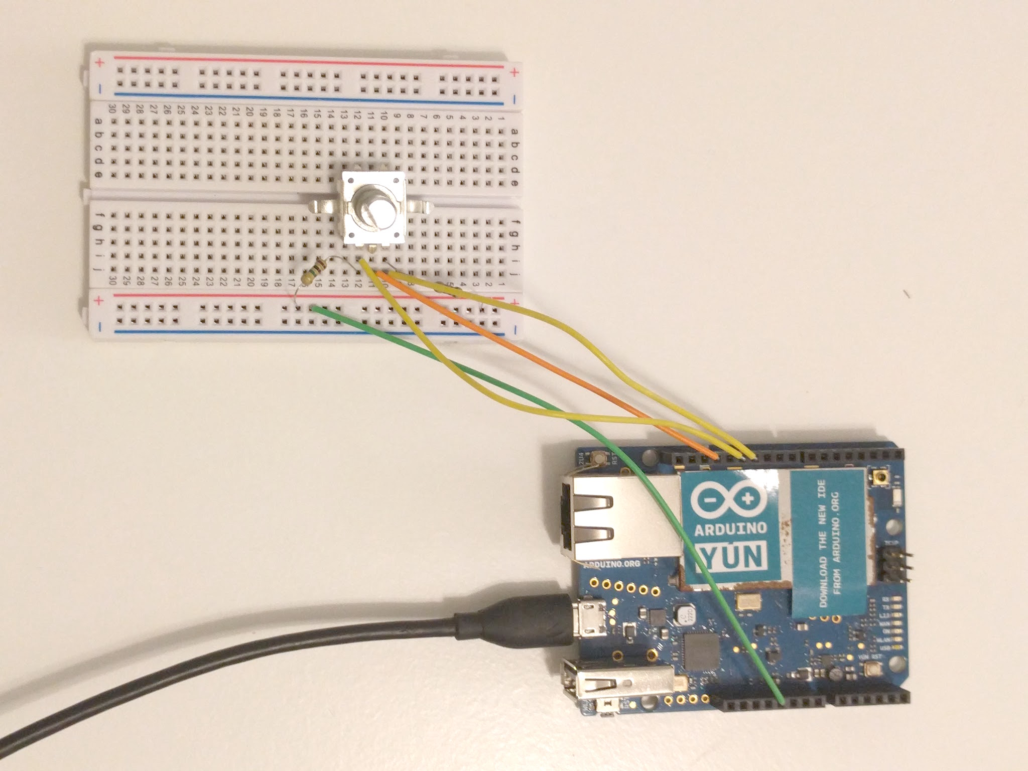
- Here's my code
Next steps
- Integrate 6 rotary encoders in the micocontroller we designed in class. Make the scheme - I need 12 input pins, 2 for each encoder
- Read on how to get input from encoders using interrupts outside the loop() function
- Read about debouncing on Arduino's page
Update
- I integrated the speaker with my input devices and used it with a Atmega328p. You may see full details of this integration on my final project updates page
- Here's a video of the board working