Capacitive Sensor - Interface
I started off this week by rebuilding a new and imroved rotary sensor. Early investications revealed that the capacitive sensors have a huge amount of noise from the external environment, so I in this itteration i added a lot of shielding - on the top, sheilding around the capacitive plate, and sheilding one the base.
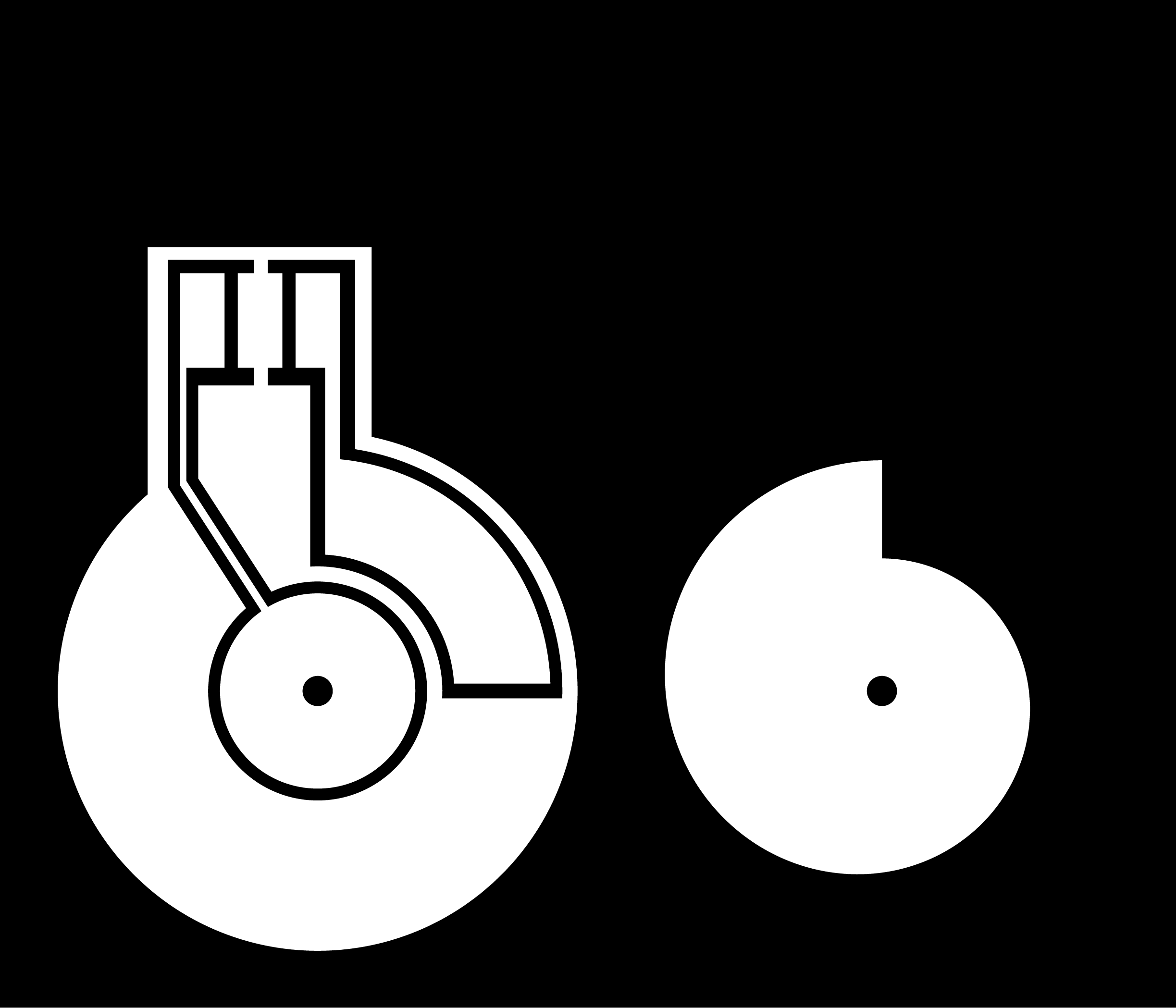

I hammered the sensor onto some wood, in such a way that there was always an air gap between the plates. In the future i think that a thin piece of paper would be a better solution to the problem of contact. Another key problem is iff one place moves a bit closer to the other - it can throw off the measurement. So it might also be beneficial to have a symetrical collection system such that alternate pads cancel eachother out.
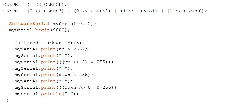
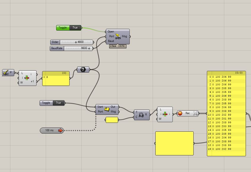
The initial signals that i got from the sensr were very garbled. It took me a lot of trial and error to work out how to fix these issues. The solution i found in the end was to write the signal using arduino software serial commands. The problem with this is that Neil's capacitive sensor scripts sets the clock on the Attiny45 chip to run with just one clock dividir, when the serial communication from arduino requires the standard 8. I found that adding a bit of code to switch the clock cycles back to 8 allowed me to send the serial communication, and then switch the clock back to 1 dividor for Neil's script to make the capacitance calculations.