0: Final Project
A.Initial concept
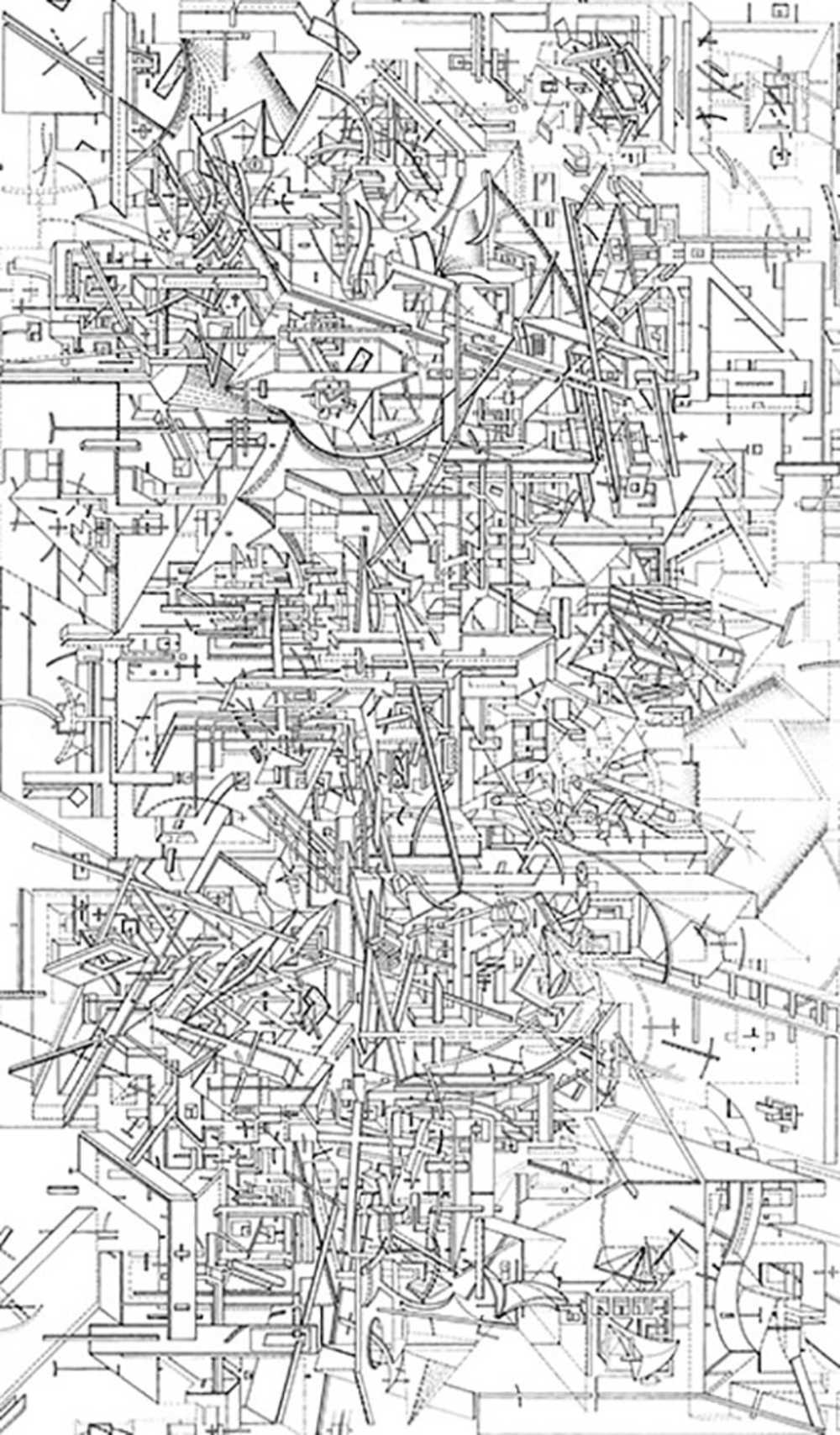
I am interested in making a drawing machine. It's interesting to me because drawings have a material quality, a sensibility of craft, that printing often does not offer - and something really fascinates me when machines produce drawings. It's kind of a Turing test, in a perverse way; it's asking the machine to replicate imperfection. There is something unsettling about how machines mimic lingering hesitation of the hands that creates variable thickness in line.
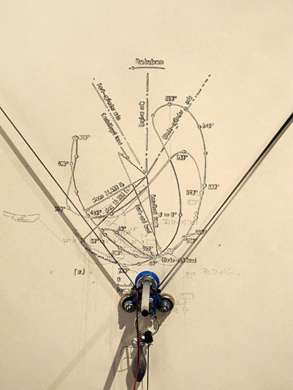
Drawings are procedural. It implies continuous feedback between the drawer and the drawn; a drawing like this is often an artifact of process rather than a visualization of a preconceived state. So my question is: can I make a machine that draws spontaneously, and 'see' what it drawn so it builds on the previous drawing rather than draw over it?
B. Project Update - 11/15/2018
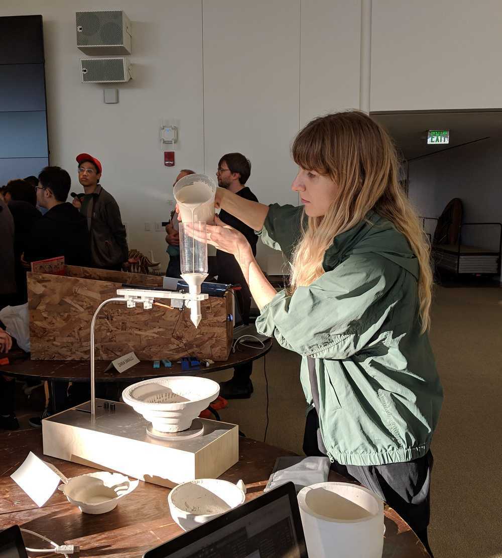
Dalma and I decided to join our efforts and focus on bringing together the idea of 'drawing' and 'objects' by creating a ceramic dripper, something similar to Studio Joachim Morineau's Moca machine.
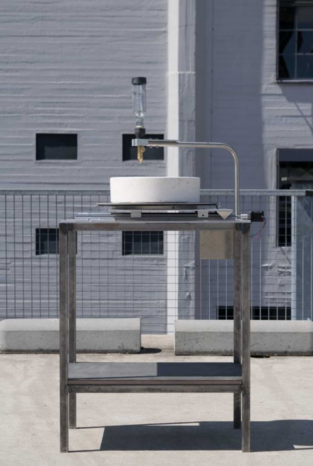
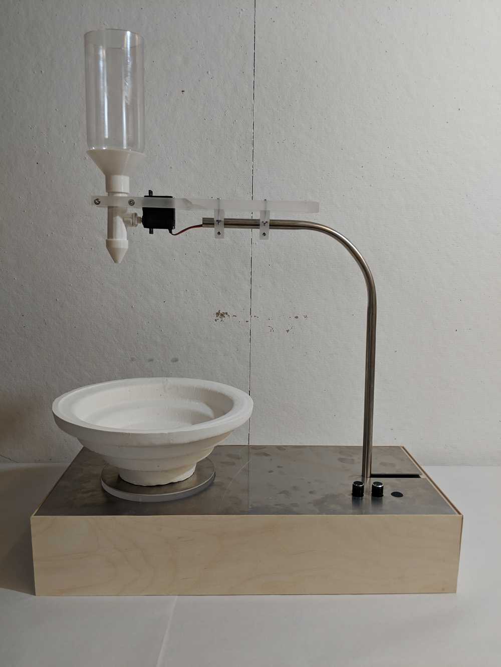
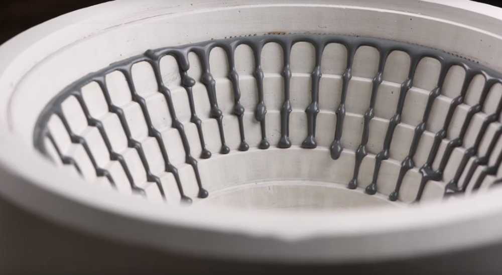
By dripping slip casting ceramic onto a plaster mold on a rotating platform, the machine creates procedural artifacts- something close to what I had wanted to achieve with my drawing machine. We are interested in the 'found' forms that results from aggregate material behavior. The slip casts slides from the angled walls of the plaster mold and creates interesting geometrical configurations depending on the speed of dripping vs. speed of the platform rotation. The slip cast hardens over time and creates a free-standing ceramic sculpture.
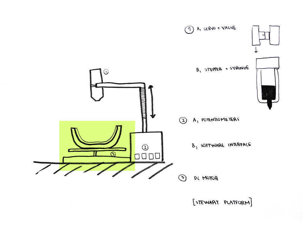
Our contribution is to add the functionality of changing speed of dripping through an input/output device, as well as implementing an input device that controls the speed of the rotating platform. We divided our contribution into two components: the dripper, which Dalma's page will focus on, and the rotating platform, which is documented here. We designed and made the plaster mold together using cnc'ed blue foam.
C. Bill of Materials
We recycled (scrap) plywood, aluminum, 1/2" acrylic, and we bought a 36" steel tube for $14. We used filament and plaster from the ACT and Architecture shops (many thanks to Graham.) The clay was $12 per a gallon bottle. We used the electronic components (one servomotor, one stepper motor) and leftover components from the machine week (bearings, etc). We bought a set of potentiometers for $5.
D. Process Part 1: Getting the Stepper to Work
On the electronics side, the rotating platform required two inputs: button for turning the rotation on and off, and potentiometer to both determine the speed and direction of the stepper motor turn. I started with Neil's stepper motor board, and added the button and LED for the purpose of debugging in the first phase, and a 2x2 communication header for the system integration phase with Dalma's components. I brought in hello.button code so I could test if I could push the button to start and end the stepper motor. This part went relatively smooth.
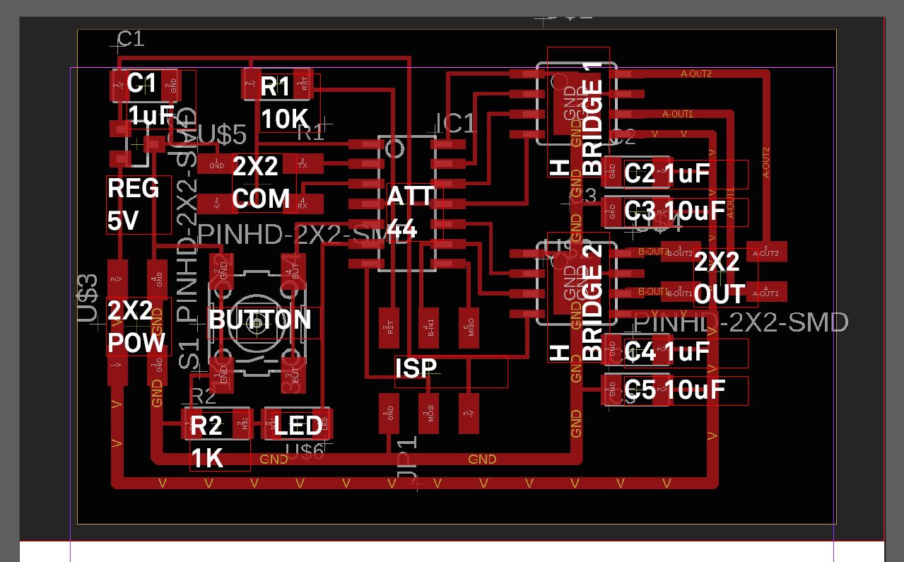
Here is the board configured to start and stop steppping after each button press/release. This is basically a combination of blink.c, stepper.c and button.c - it was late in the semester but I think I started to get a sense of how to modify codes, check it against physical inputs and outputs (buttons and LEDs) to understand what is going on. With the stepper working I moved onto the mechanical part of the rotating platform.
int main(void) {
   //
   // main
   //
   //static uint8_t i,j;
   static bool switchedOn = false;
   //
   // set clock divider to /1
   //
   CLKPR = (1 << CLKPCE);
   CLKPR = (0 << CLKPS3) | (0 << CLKPS2) | (0 << CLKPS1) | (0 << CLKPS0);
   //
   // initialize bridge pins
   //
   clear(bridge_port, A1);
   output(bridge_direction, A1);
   clear(bridge_port, A2);
   output(bridge_direction, A2);
   clear(bridge_port, B1);
   output(bridge_direction, B1);
   clear(bridge_port, B2);
   output(bridge_direction, B2);

   clear(LED_port, LED_pin_out);
   output(LED_direction, LED_pin_out);
   set(button_port, button_pin);
   input(button_direction, button_pin);

   //
   // main loop
   //
   while (1) {
      /*for (i = 0; i < step_count; ++i) {
         for (j = 0; j < i; ++j)
            step_cw();
         for (j = 0; j < i; ++j)
            step_ccw();
         }
      for (i = step_count; i > 0; --i) {
         for (j = 0; j < i; ++j)
            step_cw();
         for (j = 0; j < i; ++j)
            step_ccw();
         }
      }*/
      //
      // wait for button down
      //
      while (0!= pin_test(button_pins, button_pin)) {
      	 if (switchedOn) {
	    set(LED_port, LED_pin_out);
	    step_cw();
	 }
	 else {
	    clear(LED_port, LED_pin_out);
	 }
      };
      switchedOn = !switchedOn;
      //
      // wait for button up
      //
      while (0 == pin_test(button_pins, button_pin))
      ;
      }
   }
D. Process Part 2: Rotation Platform Design
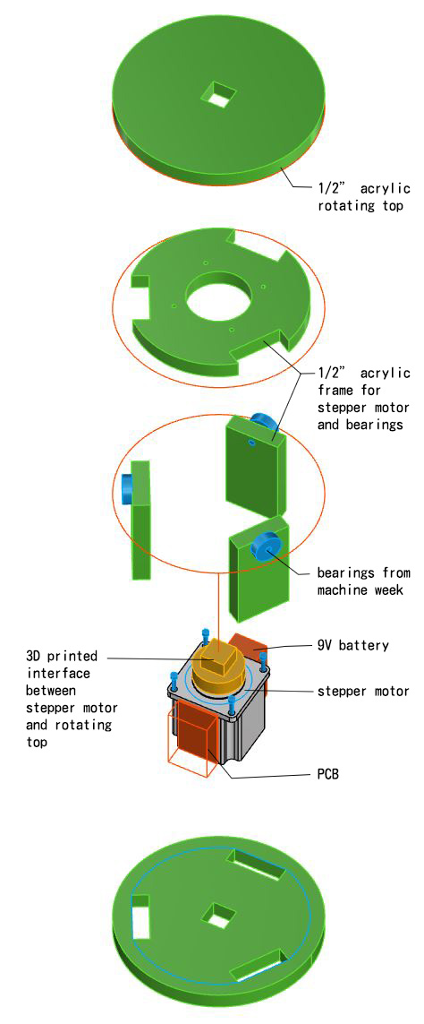
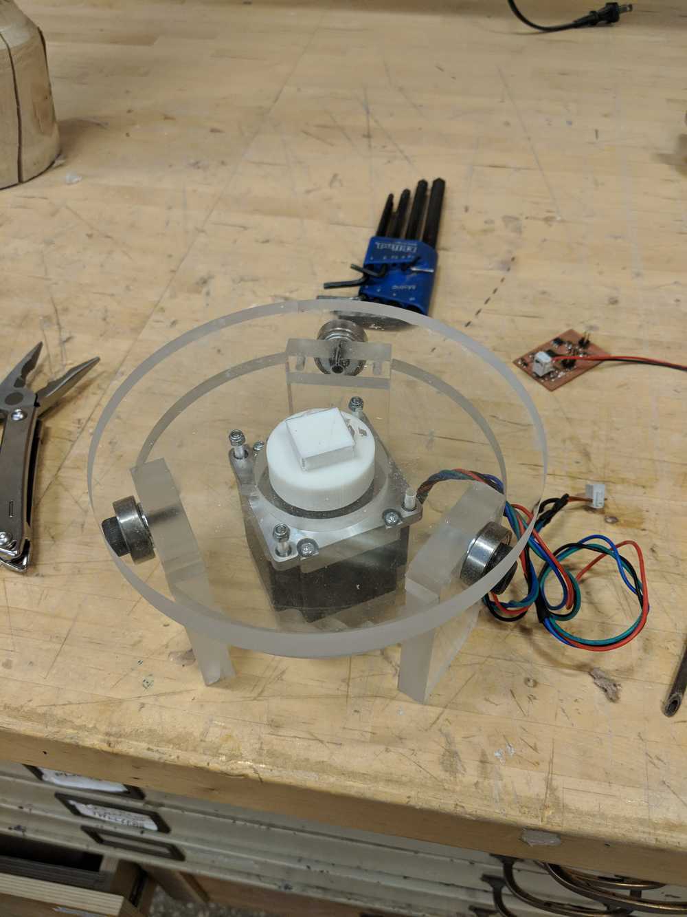
There were two options - directly driving the platform with the stepper or setting it up as a geared connetion. I chose the direct drive to keep the system simple and manageable, and hoped that stepper I am using would have enough power to rotate the plaster molds. I tried to keep the vertical load on the motor to the minimum by having three bearings around the motor supporting the weight.
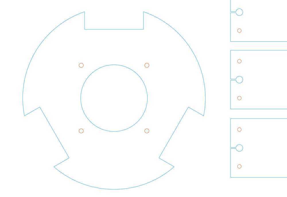
I digitized the stepper motor by measuring its dimensions using calipers and modeling them in rhino. Luckily the PCB and the 9V battery fits within the space of one of the sides- were it to be a stand alone machine I could package it within the 6" diameter. There were scrap pieces of 1/2" acrylic in the architecture shop and I wanted to use waterjetting technique as my objective for the wildcard week.
D. Process Part 3: Waterjet - Wildcard Week
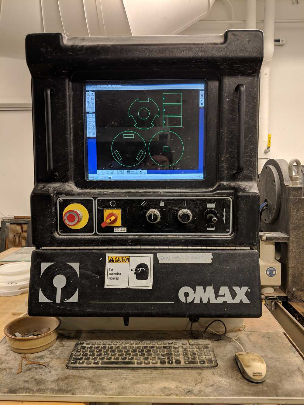
This is a stand-in for the wildcard week. Our objective is to learn how to waterjet, understand the tolerances of the system and create a dry-fit casing for the stepper motor / rotating platform interface.
Alex Beaudouin, one of the architecture shop TAs, helped Dalma and me learn the OMAX software (OMAX layout, OMAX make) and the specifics. Here is a brief summary:
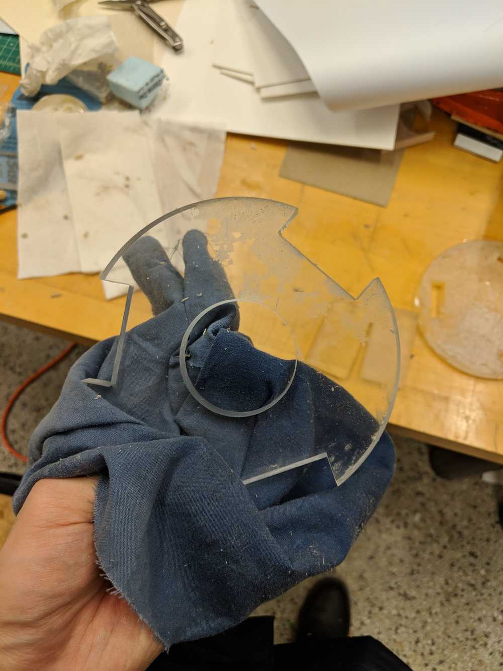
1. OMAX can cut true to size specified, with kerf about 1/32".
2. The lead in is important - the impact of the water + abrasive that hits the material in the beginning can damage the surface; lead-in about 3/4" helps to keep the impacted area away from the surface.
3. For acrylic the checkbox "brittle material" and "use low pressure" should be checked.
After few hours of testing the settings We could get the acrylic to cut well - in fact the material cuts straight and completely true to size.
Next I had to drill holes and set threads so that I could screw in the stepper motor and the bearings on to the frame. I first wanted to do this in the waterjet, but because the holes were so small there is not much room for the lead-in. One way around this was to introduce a slit - which I did for the vertical elements that hold the bearings, but for the horizontal frame that connects to the stepper motor I decided to drill the holes manually.
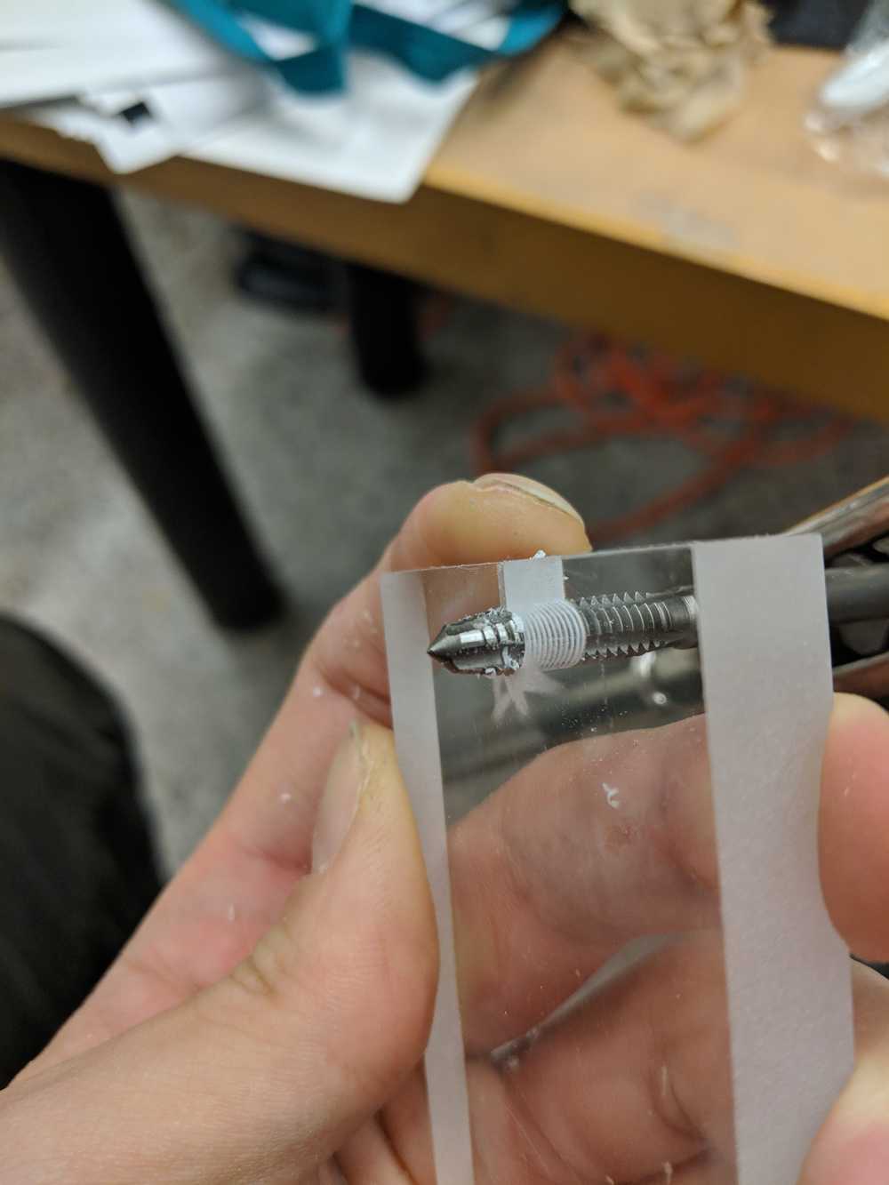
This is after assembly.
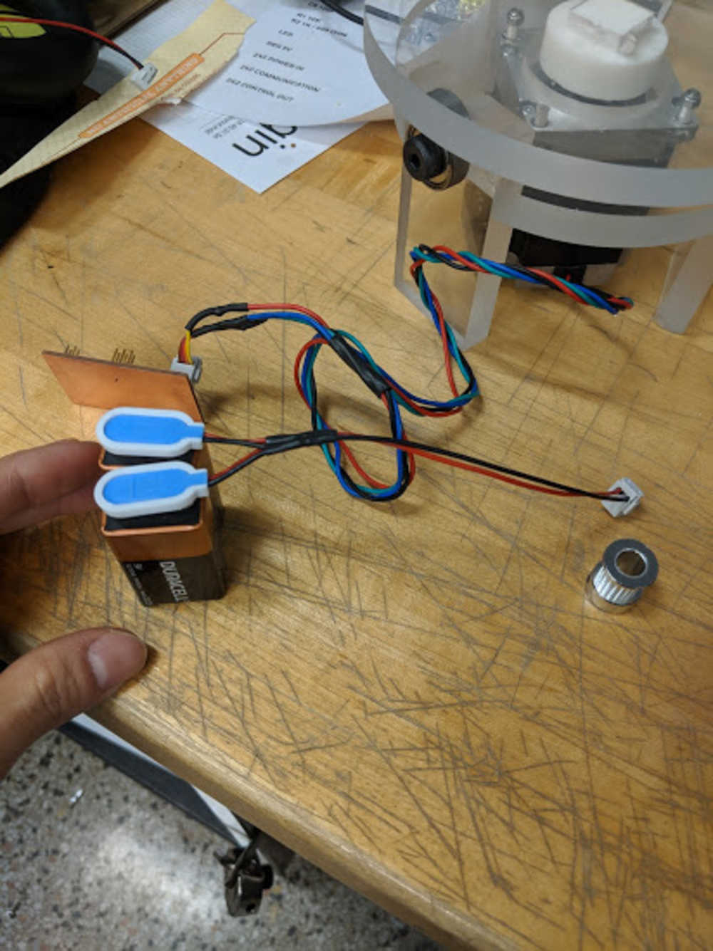
I was surprised that it was able to turn objects that are fairly bulky (power drill). But for the plaster mold it was skipping a step sometimes. With Rafa and Daniel's help I realized I could use two 9V batteries in parallel and have more current without burning out the board.
D. Process Part 4: System Integration
We designed the masterboard that would communicate with both the stepper and the servo. Given the time constraint, and because Dalma was already familiar with Arduino framework, we decided to integrate our system using Arduino IDE. While Dalma milled and soldered her and our master board, I worked on the housing of the integrated system.

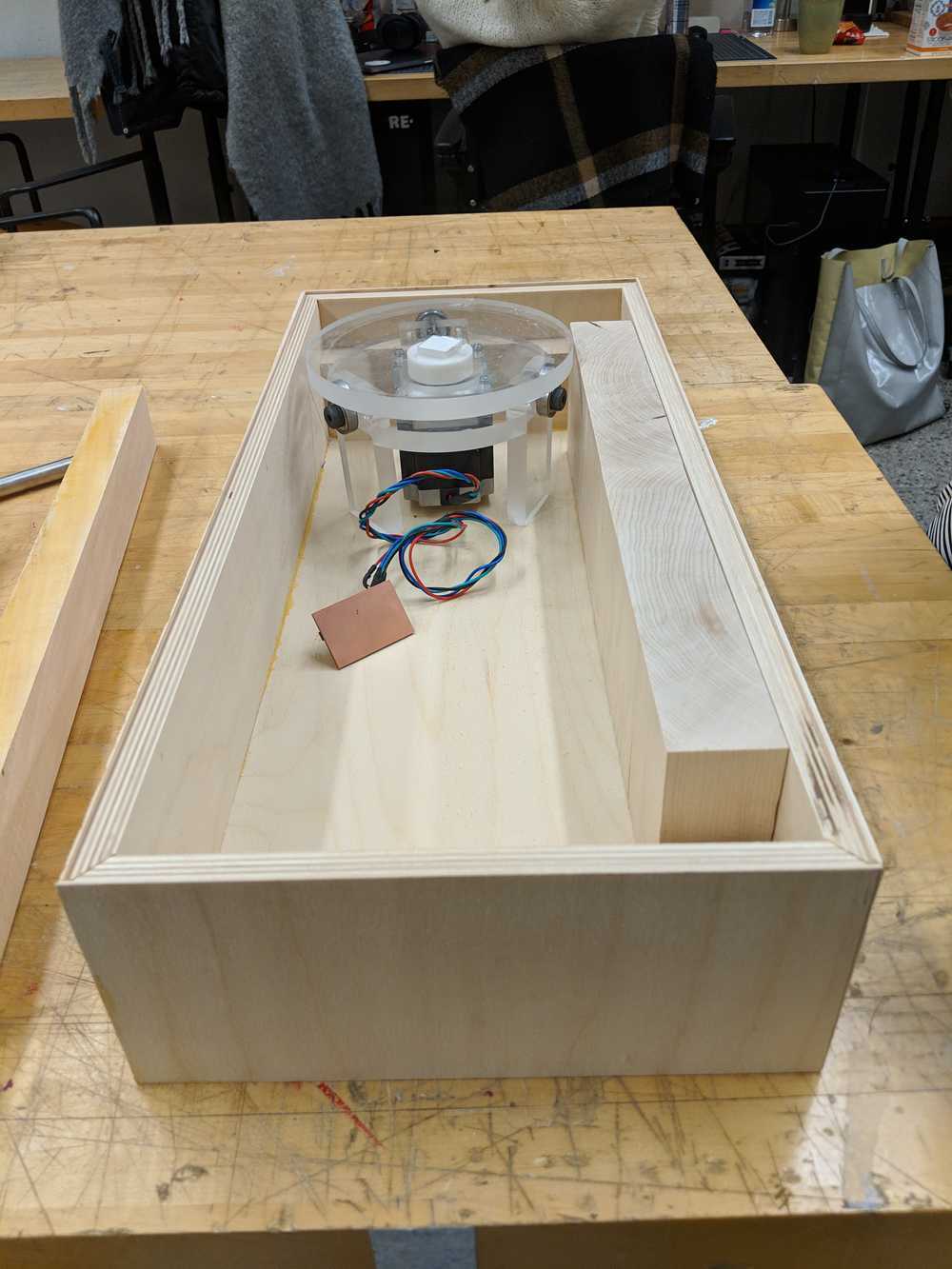
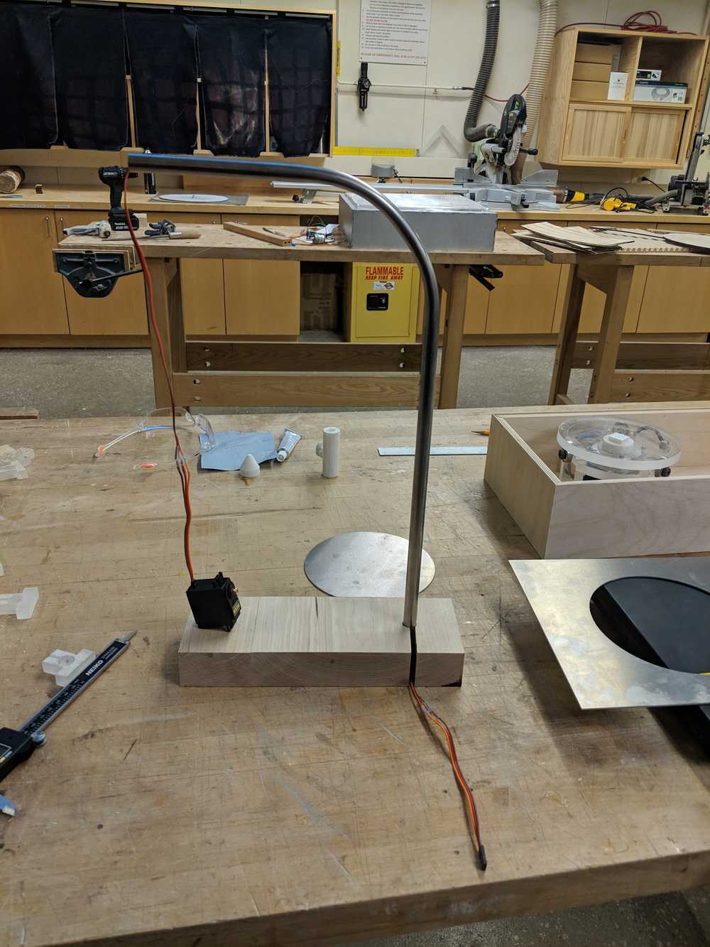
Similarly with the 1/2" acrylic, I designed around the scrap pieces I found in the architecture shop - in this case 1/2" baltic birch plywood and a 1/16" aluminum sheet. I wanted to have a wood case with the elevated edges so that it can have the metal sheet sit snug in the frame. This was done by raising the table saw just enough (about 7/16") and running the edges of the plywood on it. This leaves the 1/16" wall on the plywood. Also to hide the plywood lamination I used miter cuts on the table saw. Then I made the holder for the bent steel rod that Dalma made and fit the servo cable through-
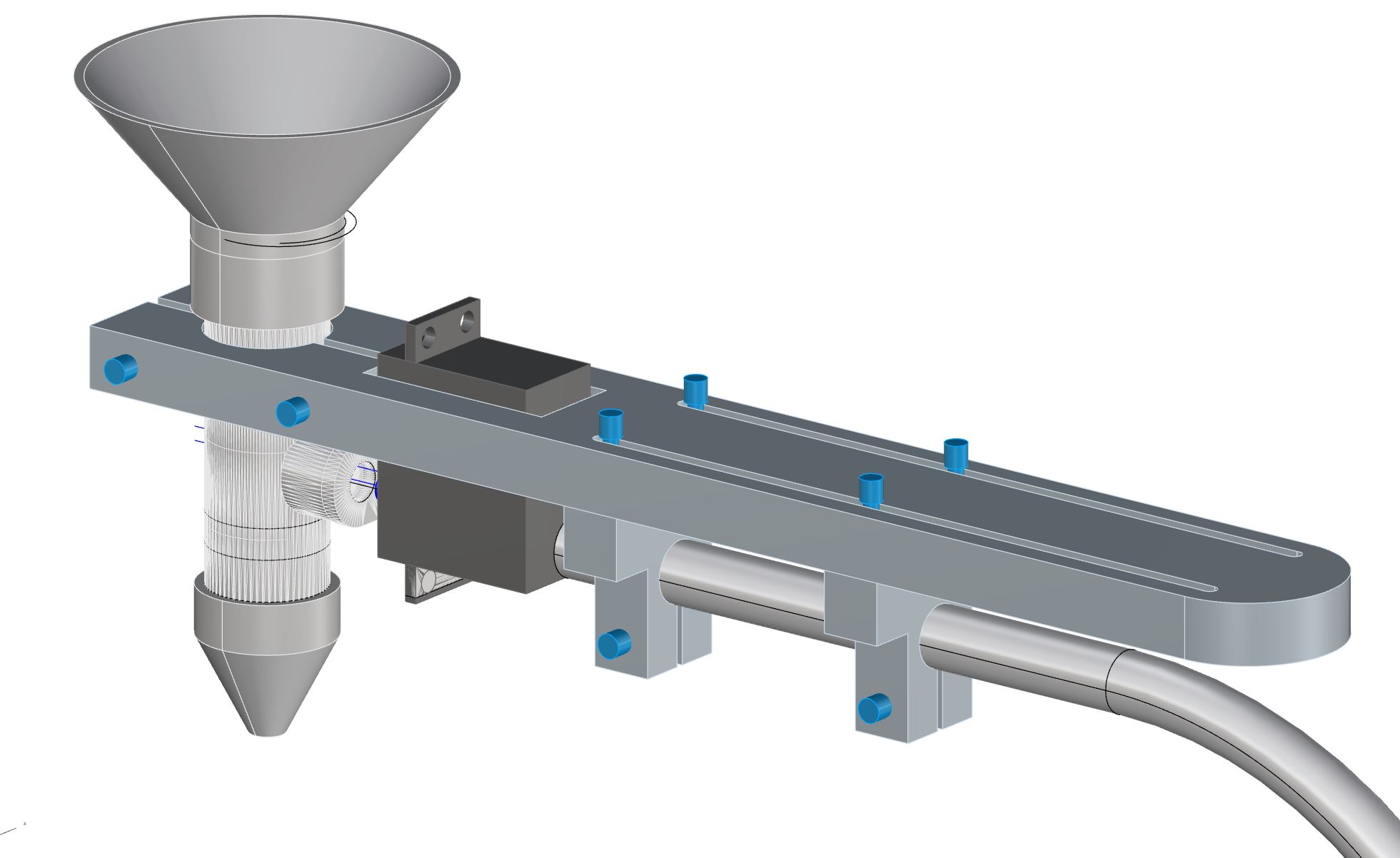
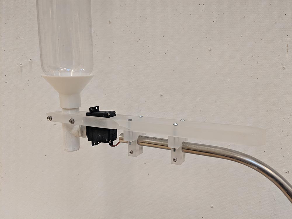
Next I adjusted Dalma's design of the valve holder. With the bit of experience with the rotating platform I gained a bit of confidence with the acrylic - I decided to make a sliding mechanism that can tighten or loosen with the use of screws. Each of the T-shapes interfaces the acrylic to the 1/2" steel rod. By using the slit and drilled holes, the connection between the rod and the top acrylic plate could be secured or loosened. Similarly, the top acrylic plate could slide along the long slit by loosening or tightening the connection between the T-shapes and the plate.
Fitting it all together. I measured the container's dimensions, steel tube diameter, and the potentiometer diameters to make the 1/16" aluminum cover that goes on top of the container. The cover was cut using waterjet.
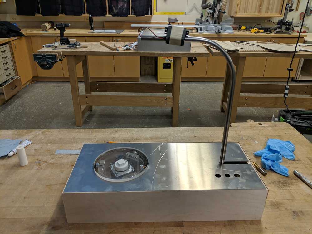
This is how it all came together. The plaster molds are documented in Dalma's page.