4: Electronics Design
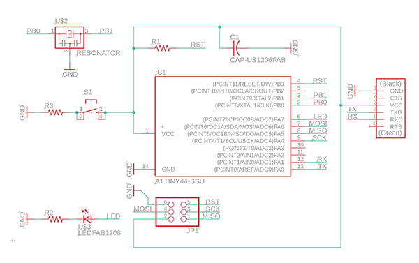
redraw the echo hello-world board
This week was mostly me trying to catch up with the class because of a week-long overseas trip. Thanks to Dalma's help I was able to catch up on the EAGLE and its less than friendly interface.
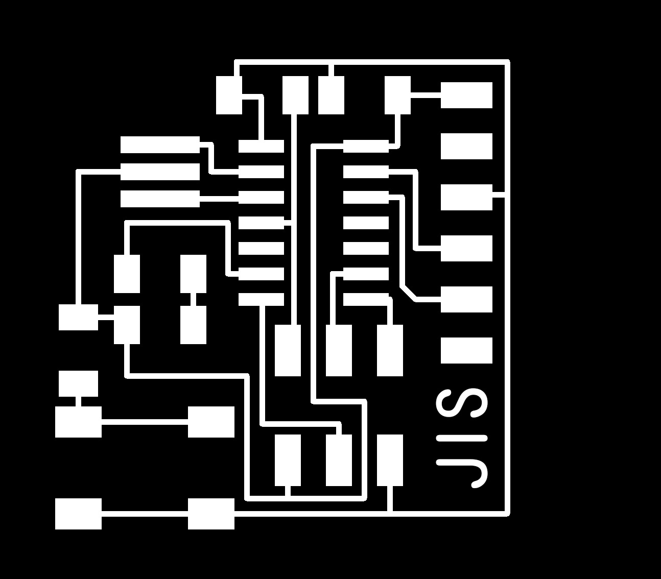
At first the board design seemed daunting because I had no idea how to arrange the board physically; after lots of tries and sneak peaks at the original file I came to something that looked to be functional.
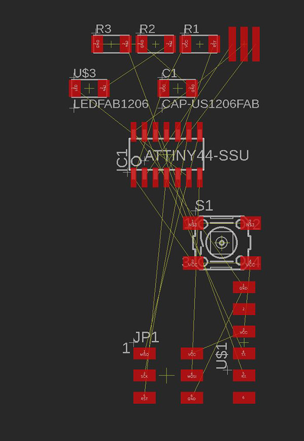
Pushing the components around to save some space in the layout.
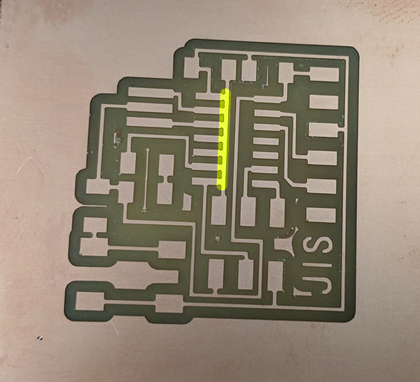
I also added the ground plane, and exported the png for the trace and fill for the outline.
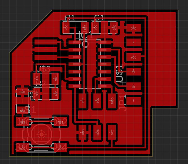
The pngs for the trace and interior fill seemed to be fine. In order to create the interior fill I first exported the outline layer from EAGLE and then put the white fill within the outline layer in photoshop.
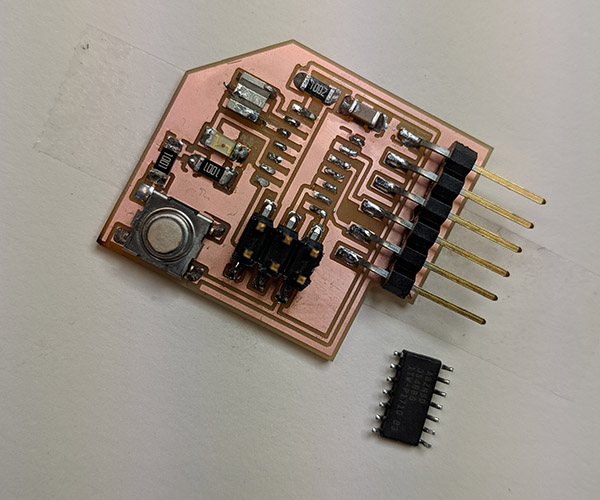
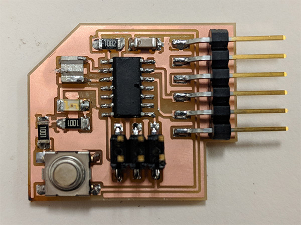
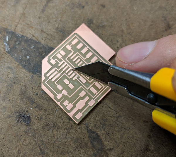
However, when I started soldering the board I realized that some of the cuts didn't go through, creating unwanted connection between ground plane and some components.
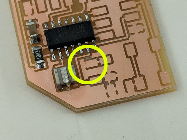
I separated the copper manually with the xacto knife (found couple of them on the board, and not sure if I missed some while I soldered the attiny44).
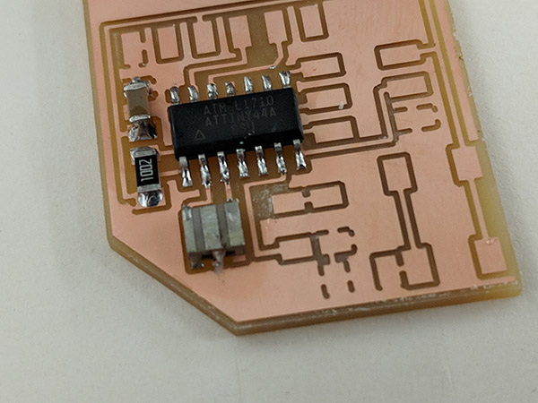
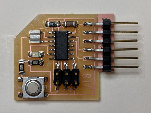
Well, here is the finished board anyways, ready to be checked for programming.
test the design
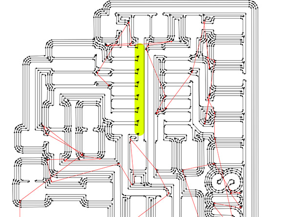
I tried to program the board many times to no avail. Jackie helped me figure out how to use the multimeter- after probing every single connection I realized that MOSI and VCC from the 2X3 header pin was communicating when it shouldn't. In fact, MOSI was communicating with a majority of components on the board; I tried resoldering the 2x3 header pin but it didn't help. I ended up remilling the board, this time without the ground plane just to make sure I am not shorting the circuit because of it, and in the process realized that the circuit that connected RST to resistor was connected to the whole left side of the ATT44 board.
It was weird because the design rule did not catch this in the EAGLE side, but in the process of transfoming PNG into the cutlines the gap between the RST circuit and the other pins got omitted. It must have been just below 1/64".
I manually severed the connection between the pins using a knife, resoldered everything, and checked with the multimeter to make sure that there were no shorts, and it looked like everything was fine.
I checked the board and I still got the infamous rc=-1 error. Dalma told me to try with the Arduino instead and I got it to make the LED blink at least, so there is some communication between the USBtiny and the board that I made.
Afterwards I opened up my other board and of course, I found the same problem of clearance. I've got to check this before I mill the board next time..