8: Input Devices
add a sensor to a microcontroller board
This week is again in my less familiar territory. Also because I wasn't able to use the ubuntu OS that I set up using the VMWare in my home desktop, I had to replicate the process I did two weeks ago on my laptop. This time I am going to write the steps down so I don't have to search online all over again..
Steps for setting up programming environment in Ubuntu:
1. install VMWare
2. download and install Ubuntu using iso image
3. install python: sudo apt-get install python
4. install pip: sudo apt-get install python-pip
5. install tkinter: sudo apt-get install python-tk
6. install pyserial: pip install pyserial
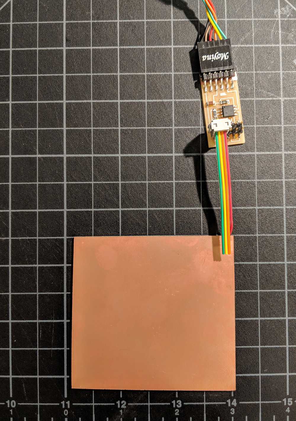
7. connect USB-FTDIserial-board to a USB port
8. check which port the board is connected to: dmesg | grep tty
9. authorize the use of the port : sudo chmod a+rw /dev/ttyUSB0 (USB0 in this particular case)
This should set the computer up for communicating with the board.
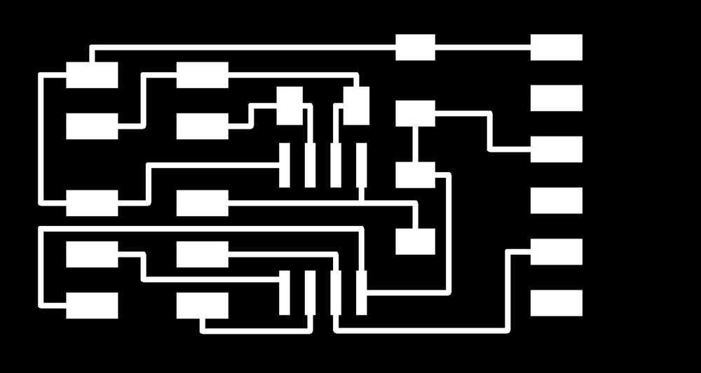
Back to the EAGLE. In this case I am starting with Neil's step response - load - board. Setting it up went smooth this time, and I was able to layout the board without trouble. I remembered that the last time I milled some of the lines weren't cut because they were just smaller than the 1/64" diameter (but not flagged by the design rules.)
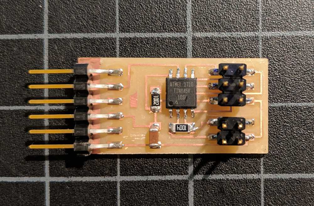
The board looked fine when it came out of the mill, no parts were touching. Soldering check.
The problem is that I am still not quite understanding what is going on in the hardware-to-software side. I need to spend more time reading datasheets and other people's projects to grasp what is going under the hood. This is kind of the biggest barrier for me - cracking open this black box.