2: Electronics Production
make an in-circuit programmer
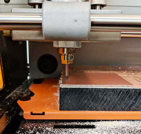
This week's assignment was more or less straightforward. Here I am setting up the Roland SRM-20 with a 1/64" end mill for the machine characterization.
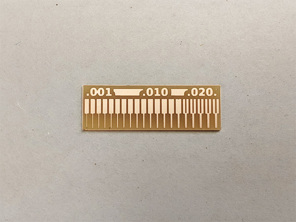
The end mill was new, and it produced a very clean test cut; it was even able to capture the .001 inch thick line.
When I was tracing my own PCB I noticed that some lines were not cut all the way through the copper.
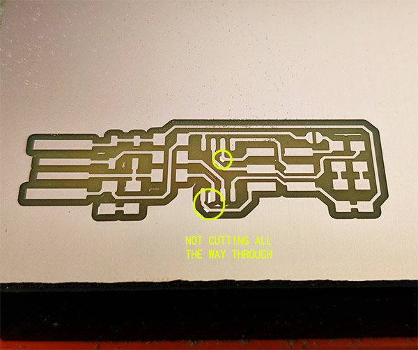
I think it was because the board was not secured completely flat with the double sided tape. In the video you can see that the board is moving vertically as the mill moves around.
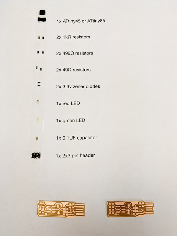
After some bit of XActo trimming, I was able to get the uneven surfaces off from the board. I also made another board in case the first one goes wrong. Ready to solder!
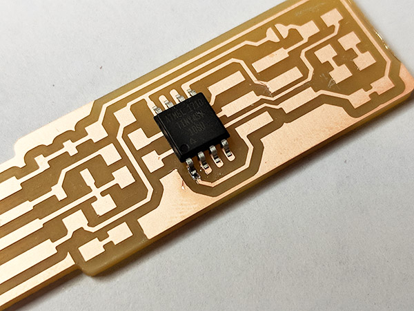
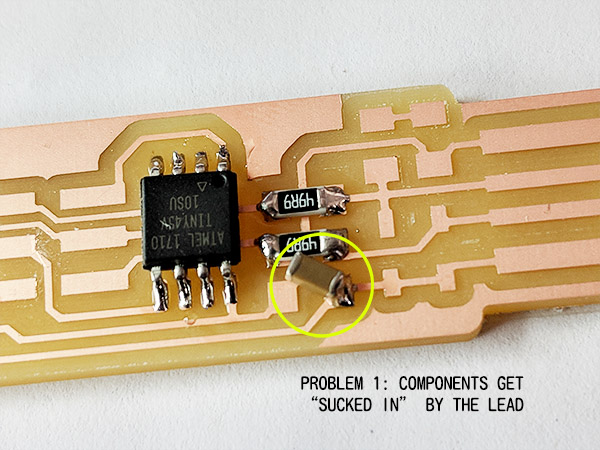
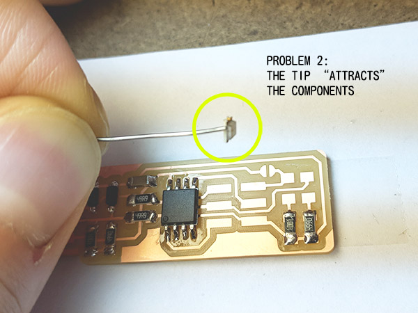
The first connection. It took some time to understand how to position the component and apply heat and then put the lead on without having the component get moved around by the lead.
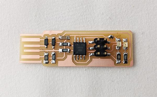
Here is the first one I made.
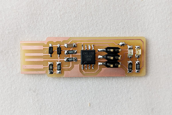
And another one, to get a better gist of soldering. Not too different.. Our TA Jackie told me later that it is generally better to keep the shape of the connection concave rather than convex.
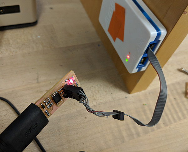
Programming the PCB was straightforward partly because the initial setting up of the softwares and firmware were already done on the lab computer. I followed the instructions, typed in 'make flash', 'make fuses', and 'lsusb' showed my device!