1: Project Management / Computer-Controlled Cutting
cut something on vinyl cutter
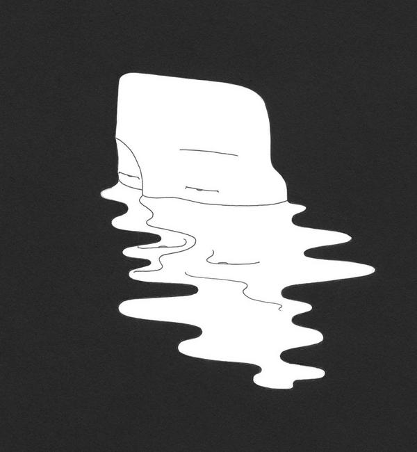
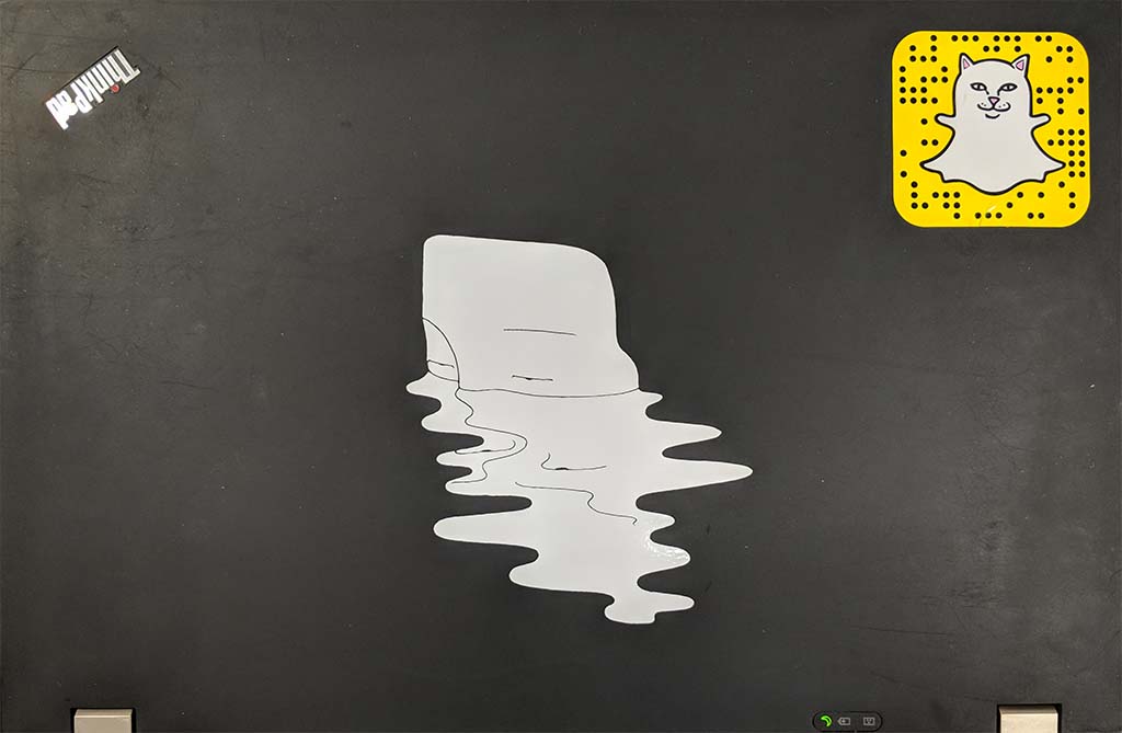
I started out with Daehyun Kim's illustration. I was curious how accurate the vinyl cutter could capture the author's delicate lineworks.
Using the CAM mods, this original photo goes through series of transformations to be vectorized for cutting paths. The first step is to threshold the image; three values (0.8, 0.5, 0.2) are shown here.

Next is the effect of offset- it seems that the script is set up in a way that values less than 1 have no effect on the image. Negative values also do not offset the image in the opposite direction. Three values (1.0, 1.5, 2.0) are shown here.
The outline view shows the continuity of the path. 0.8 Threshold has good continuity but is on the thicker side; with 1.0 offset the line gets thin but the linework is no longer continuous. With 0.5 Threshold the same problem happens. I've settled on 0.6 as the threshold that gave the thinnest line without breaking the continuity.
The last parameter for vectorization is the vector fit. 2px, 1px and 0.5px fit (smaller values doesn't affect the density of sample points) shown here, and additionally I've tested it with image twice the size of the original.
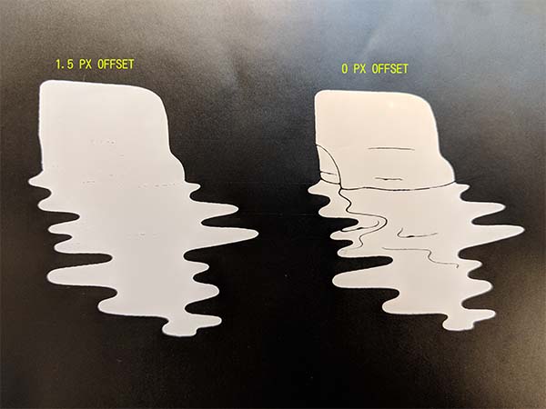
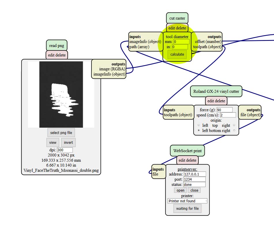
Upon sending the vectorized file to the vinyl cutter I realized that the offset parameter was actually automatically generated by the tool diameter and the resolution of the image. The left picture shows the default setting (10 mil tool diameter) offseting the toolpath by 1.5px and essentially wiping out the linework. I worked around this by setting the tool diameter to 0.
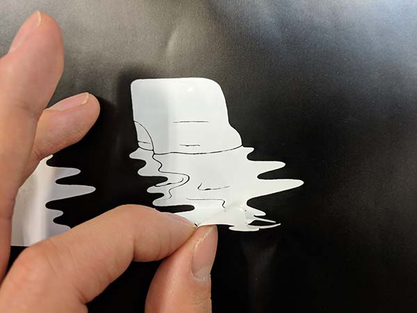
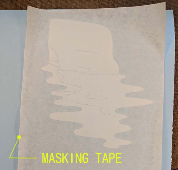
There was another problem of keeping the relative location of the discrete vinyls. Masking tape helps to keep the vinyls in their respective position while transfering to the final surface.
design, lasercut, and document a parametric press-fit construction kit
I got intrigued by the Laser Origami project by CSAIL and wanted to explore ways to use laser cutter beyond the cutting and scoring operation.
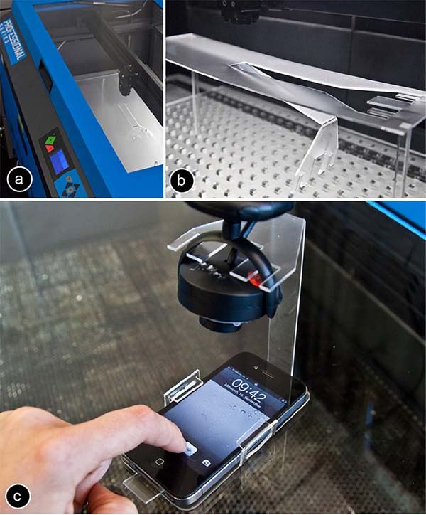
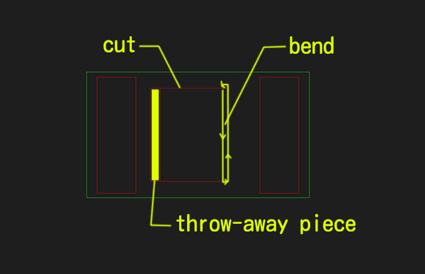
I followed the setup posted on the site. Cut lines at 2" from the top of the material, and multiple passes of out-of-focus beam that moved in circular motion. There was a sacrificial piece to avoid having the material get stuck on the hinge. The material is 1/8th acrylic.
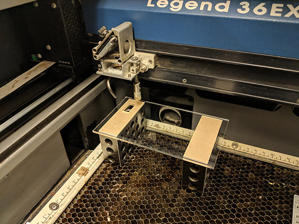
The first pass, 3" from the top of the material with 80% speed and 20% power, was too strong and started to burn away the material immediately. There was also no sign of the material bending by gravity- I had to manually bend it after it was heated.
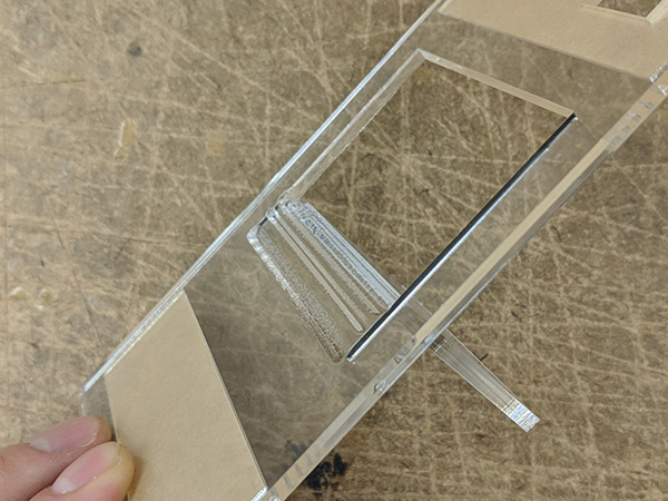
After some iterations and some changes in settings I was able to get a relatively clean bend (still manual bend after heating). The beam was 3.5" away from the top of the material, speed 80%, 10% power, and looping 50 times.
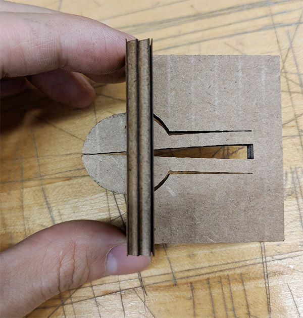
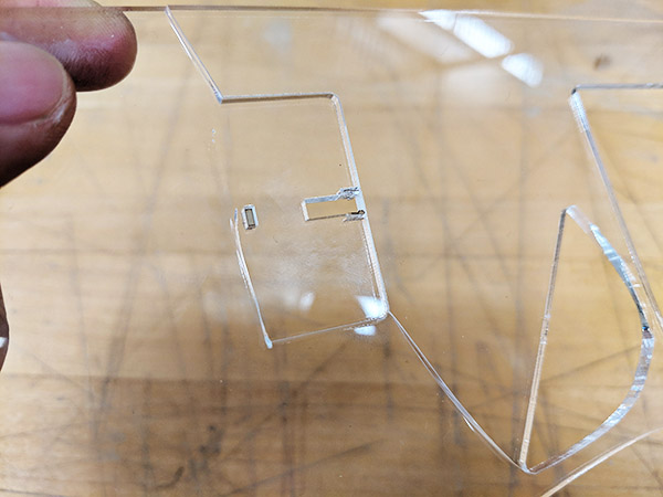
Next onto the press fitting. Here I am testing out differnt parameters for the notch with flexible flaps (joint length, notch length, notch depth, kerf, etc..) This was set up in Grasshopper to iterate through to find a good setting.
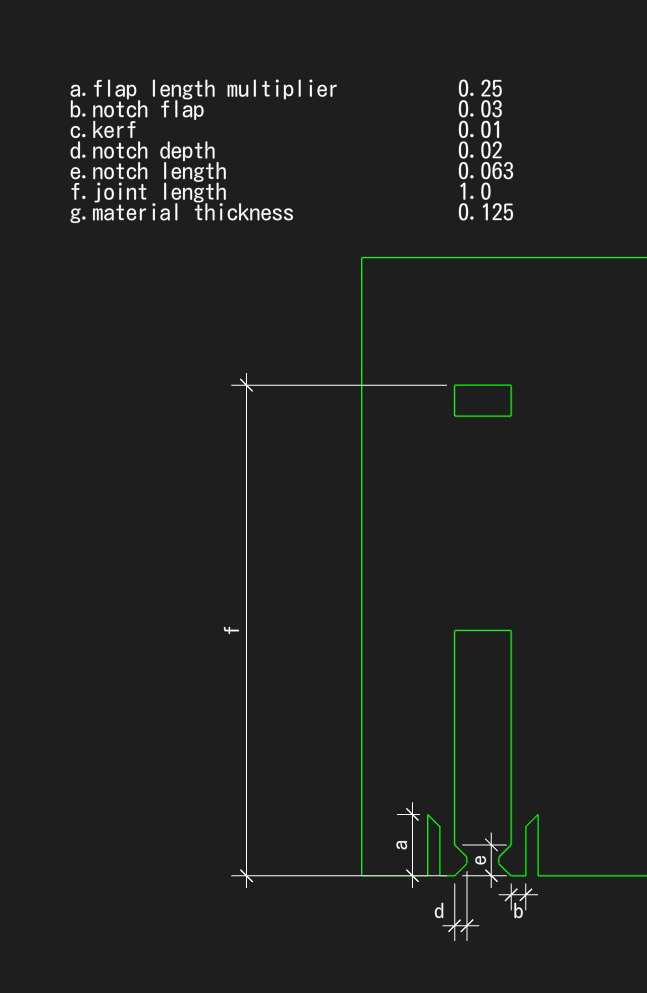
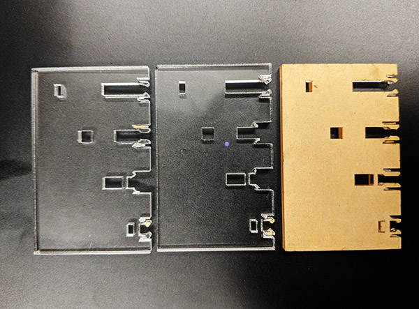
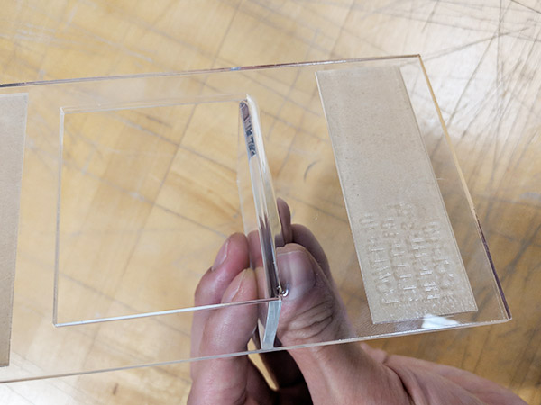
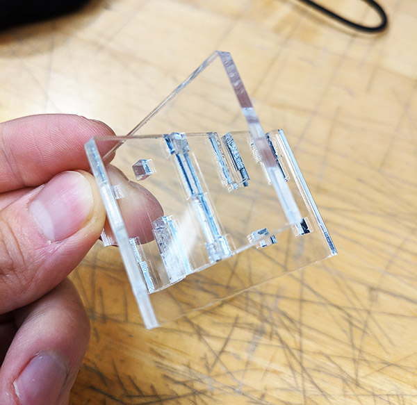
The best result I had was with very shallow and relatively short notch, and also thin flap. Acrylic is very brittle, so there is not much room for the material to bend. Here the picture shows .0625" notch length, .006" notch depth, .025" flap depth, and .15" flap length.
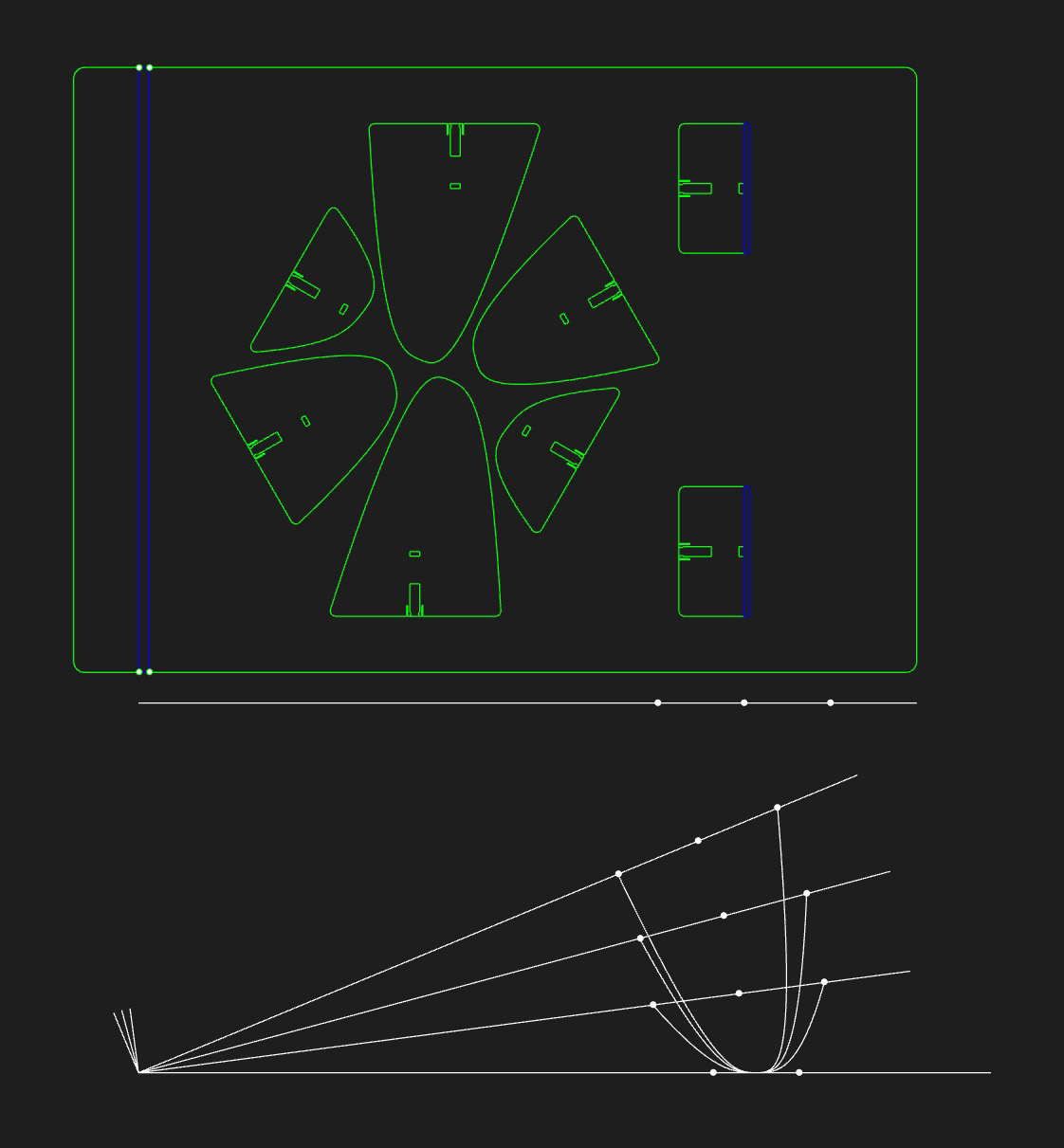
For the final design I wanted to employ both the bending and press fit technique, and thought of making a laptop stand with adjustable height. The blue lines would be where the acrylic sheet would be bent, and the 3 sets of legs would press fit onto the bent pieces.
...And this happened. What I realized is that the setting that yieled a good result for the test pieces were specific to the length of the path. Because the path was smaller in this case the acrylic overheated, and also heated unevenly across the path. After my second try I ran out of acrylic.
So instead I took some lessons learned from the press fit material tolerances and the bending behavior, I made paper container with the cardboard. The operable flap, for example, can be worked in the other direction - and as long as its movement stays within the elastic deflection. The closing mechanism is a combination of the pull from the kerf and the push from the operable flap.