how to make (almost) anything
Final Project: CastLight
Project Tools/Resources:
Roland SRM-20 Mill
Prusa i3 MK3 3D Printer
Autodesk Eagle
Adobe Photoshop
Arduino IDE
Soldering Equipment
Concept Development
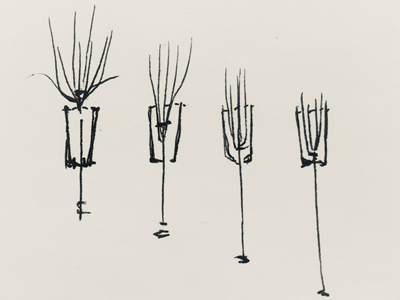
My initial idea for the final project in week 1 was to make a mechanical flower that perhaps would bloom in the dark, or open and close with sound.
But, I walked away from embedded programming week a little obsessed with LEDs, so I've also been toying with designing a capacitive touch lamp.
I met with Molly to talk through final project ideas, and she had some really nice precedents related to mechanical flowers:
- Geoffrey Drake-Brockman, Floribots
- Studio Drift, Shylight
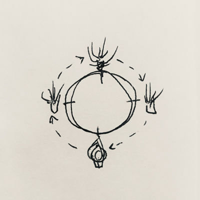
Both of these precedents use a vertical motion/mechanism to trigger the opening of their forms, which was something I hadn't considered at first--my first thought was something more rotational--like this geared mechanical flower kit from UGears. There's a simplicity to the vertical movement that would be worth pursuing.
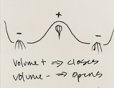
Sound
Time & Light
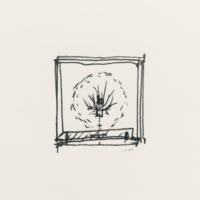
Encased
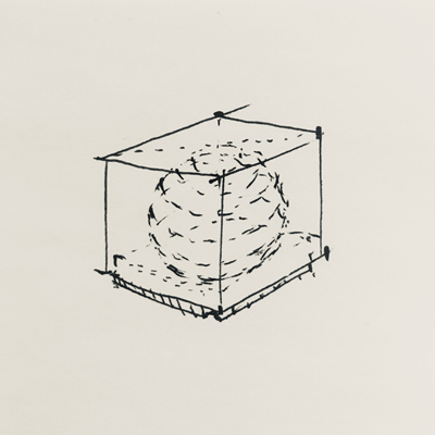
I am, however, more interested in designing lighting of some kind. Thinking through ideas for the form of the flower sent me on a chase for image inspiration, I came across the artist Peter Alexander's work, and was drawn to the similaritities with how I had begun to imagine initial form within a form for the casing around the flower. The play of color is especially nice, and I can imagine that coming from either material or through light. There may be the chance that the flower and light could combine at some point down the road, but focusing on lighting feels like the right direction and scope for me.
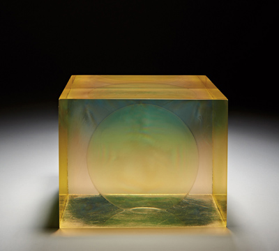
Green Sphere, Peter Alexander
1967
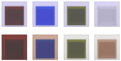
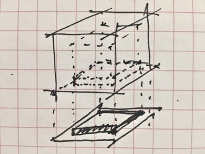
A few quick studies about color and assembly. I've been thinking more about materials, and probably will go forward with casting the light's form out of rubber. The frosted/translucent quality of the Oomoo Sorta-Clear could work nicely with nested forms, especially as the color, locations, and/or intensity of the light may shift.
Electronics Design
I've gone back and forth a few times about what I wanted the behavior of the lamp to be, particularly if I wanted to introduce color LEDs or not. I've finally settled on restricting the light color to white and red LEDs, which will be arranged in two separate parallel series on the same board, and can be adjusted and mixed through the use of two capacitive touch strips--something along these lines:
Zach has graciously been meeting with a few of us "architects" after class on Wednesdays the last couple of weeks to offer some project advice and direction, which has been super helpful. Based on our conversations, I put together a diagram of the macro vision for how I saw the electronics all interfacing together, and met with Anthony during office hours to double check that I was on the right track. Also, super helpful. He caught that I wasn't routing 12V to the LED board at the right location (no need to go through the touch processor), and that I needed to add an N-channel mosfet.
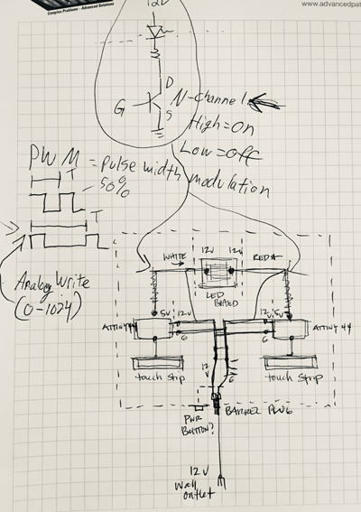
Zach also gave me a strip of Super Bright Warm White LEDs from his personal stash to use on my LED board. He wasn't sure what the part number for them was, so for now, he said to assume they pull 3V and 50 mA. After some internet digging, I'm pretty sure I've found them (), but using this as a starting point, I redesigned the LED circut to include a mosfet, and did the resistor calculations for the white and red LEDs I'll be using.
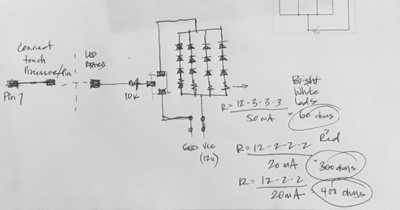
Revised LED circut adding Mosfet & resistor calculations
Because I'll be driving several leds in series, the light will need a 12v power supply, and the touch boards will each need a regulator added to the design in order to send 5v safely to the ATTiny44 processors. Zack suggested I look to Neil's DC motor board as an example of how this happens and what components are needed.
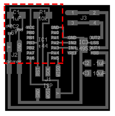
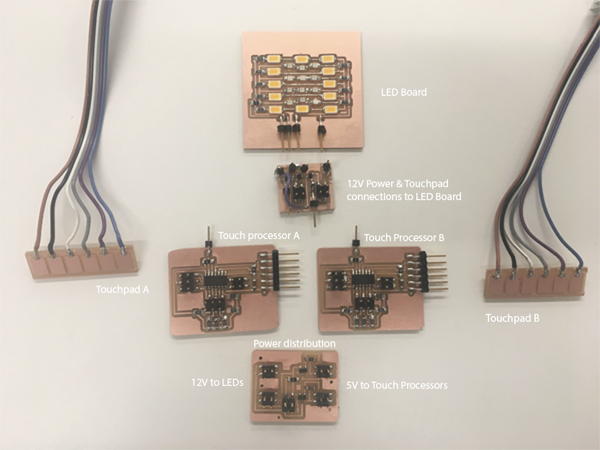
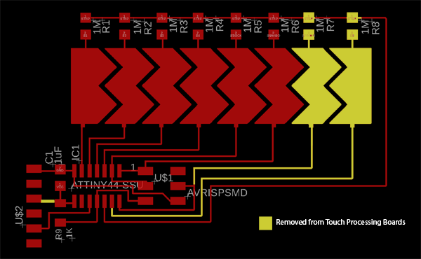
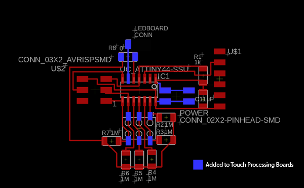
Moving on to Eagle, I designed the schematics and copper for a power distribution board, which will take in 12V from a 12V wall plug to the LED board, and also regulate that voltage to 5V to run the touch processing board. The touch processor board is a slight redesign of the touch strip board I made earlier in the semester for networking week (based off of HTM alum Akash Badshaw's touch slider). I downsized the touch strip to 6 pins in order to free up space for an LED connection to pin7 on the ATTiny. I also separated the touch strip pads into a separate board, designed in Adobe Ilustrator, in order to more easily integrate them into the light assembly. Lastly, I finalized the schematics and copper design for the LED board, which will integrate both circuit strings of LEDs (red and white).
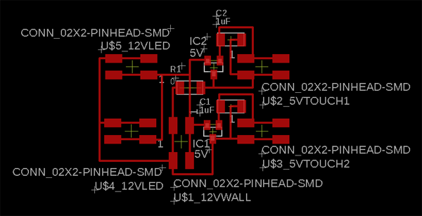
Power distribution board
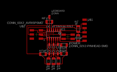
Touch processor board
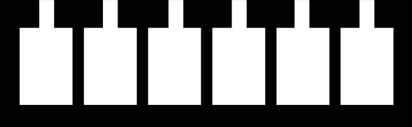
Traces for touchpad
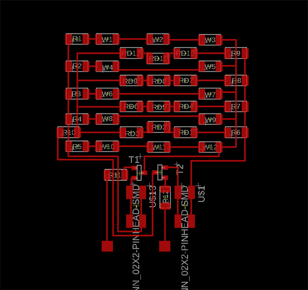
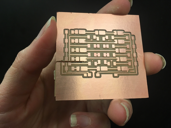
LED board
Fabrication: Light Housing
Before I began fabrication for the light's housing, I did one last round of design in Rhino to finalize the dimensions and relationship between the separate castings. One thing that can still be fluid for a while longer is the specifics of the base of the light, which will support the cast rubber 'shade' and conceal the electronics.
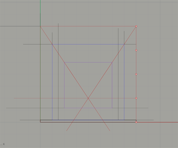
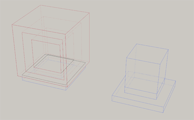
Final relationship of nested casts and base to inform mold fabrication
The shade will be cast in two stages, the first will form the central void and shell. I've settled on embracing the natural color of rubber, which I'm hoping will be reminiscent of amber, and work well with the red and white LEDS I'm using. Once that has fully cured, that form will be cast into another, outter layer of rubber. Because the forms are really very simple, I decided it was overkill to mill it. I chose instead to fabricate this step manually with plastic formwork, and foam as the negative for the central void. The hot glue was messy and a little annoying to use, but it's a fairly quick technique to create simple formwork without the need for a release agent.
An important side note: check with your shop manager before choosing and casting materials. Although this rubber was a material other students had used previously in the class, and I was careful to speak with the staff at Renyold's specifically to make sure this was a rubber which could be cast in a room sized space, it was not something that Jen wanted cast without direct supervision in her shop. It's always best practice to speak with your shop manager before bringing in and using new materials.
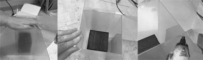
Mold for the first cast
The Smooth-On rubber comes in two parts, which are weighed and mixed at 2:1 ratio, and then poured into the mold to cure for 16 hours. It was the same process to using Smooth-On's Oomoo from molding & casting week earlier in the semester, just a different ratio between the parts. One major difference in the experience was the consistency of the material, which was much thicker than the mixed Oomoo. This led to a lot of challenge in getting all of the trapped air to rise to the top surface through tapping the mold on the table, as I had done previously with sucess. I was able to get most of the major bubbles out, but there was noticably sized pocket of air that got trapped to one corner of the form, and which wouldn't rise before the rubber began to really set at around 15 mins. This was incrediably frustrating. It seems to be a material that would benefit from degassing in a vacuum before you pour, a process Neil mentioned in class, and that is shown in this instruction video from Smooth-On.
After 16 hours, the rubber is cured, and the mold is ready to be removed. I used a utility knife to slice along the hot glue joints in order to pry apart the walls of the mold. After the outter formwork is removed, I carved away the foam volume for the center void. It appeared that I didn't get the best seal between the foam form and the outter mold's base, because there was a thin layer of rubber on the bottom of the cast, which was easily sliced away with the knife. This is probably where the air had gotten trapped. In general, the first round came out pretty well, and I was particularly happy with the color.
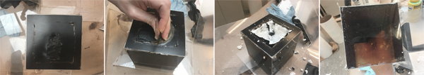
Removing the first cast from its mold
First cast done!
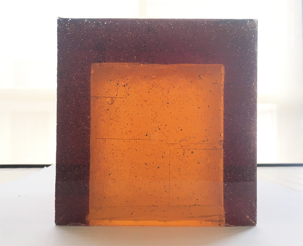
I repeated the process for the second casting, being very careful this time to get a better seal between the foam insert and the mold bottom. It was also inmportant to make sure there was a tight seal between the foam and the first cast, so rubber wasn't able to move into the central void. Smooth-On also provides a casting calculator on their website to help estimate the amount of material you need to mix to pour your formwork, which was very helpful. It ended up that I didn't have quite enough material to fill the form fully to where I had originally planned, which would have encased the entire volume and produced a cubic form, but there was enough to fill it partially, and to allow the central volume to be exposed. Not what I planned, but I like this unanticipated variation, and it actually might produce more interesting affects when lit. It would be great to continue experiementing with how these volumes can interlock in the future.
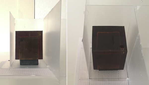
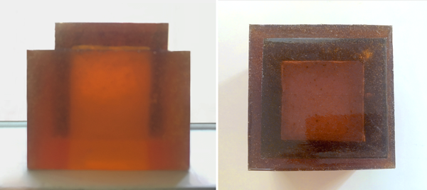
Final rubber cast
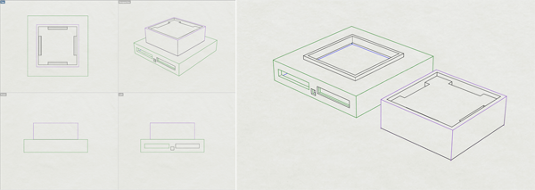
Now the rubber shade was complete, I could double check the dimensions of the form to finalize the design for the light base in Rhino, which will lift and support the rubber, and conceal the electronics on it's interior. It is a two part stand, whose top can be removed in order to more easily access and organize the electronics during integration. The bottom is enclosed on three sides. The fourth side has two 'windows' for the touch strips, and a central opening for the 12V supply. The top has a depression to allow the LED board to be inset, and side vents into the bottom allow for the connection of the LED board to the power supply and touch processor boards.
The 3D printers have been crazy busy for the past few weeks since we share them with the entire Architecture school, and final review season is in full swing (also, several were not working/out of commission). Luckily, I was able to print on one of the Prusa printers in the IDC. Wow, those are really cool machines! The resulting print quality was way better, in my oppinion, than anything I saw this semester come off of the Sindohs in Architecture; I was really happy with it.
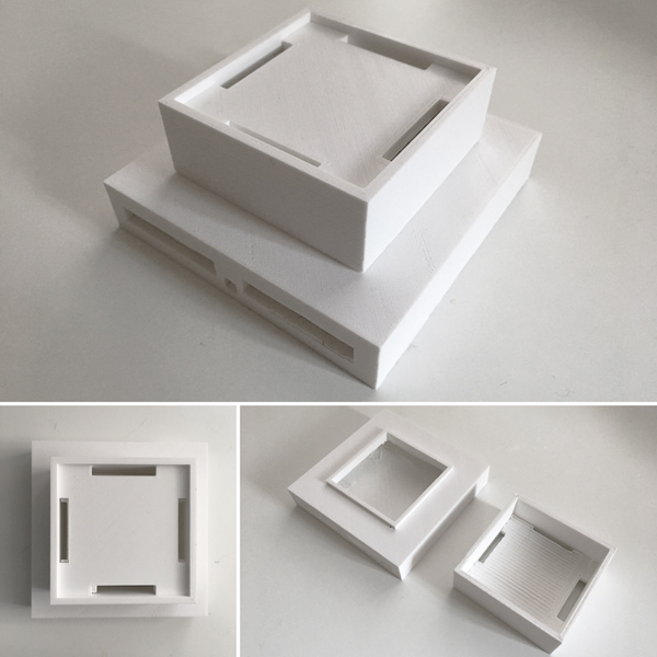
3D printed light base and electronics housing
Here is the way the 3D printed base combines together with the rubber shade:
Housing disassemblyFabrication: Electronics
After the design of the electronics was complete, it was time to hit the mill and pump out all those boards! I was able to (almost) mill everything without an issue, with the LED board last up. When I went to mill the trace file, I realized ONE BIG PROBLEM: I had forgotten to update my board design to incorporate the Super Bright White LEDs I was going to use, which have a longer body and distinctive footprint. Since there are no copies of Eagle installed on the Arch Lab computers, I had to resort to an emergency Photoshop session to alter the .png of the traces so they could be milled. A bit of a costly mistake time-wise.
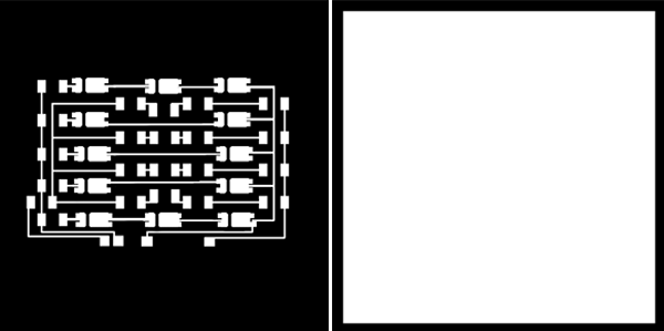
Mill Files for LED Board
With the LED board's traces milled, I moved on to mill the board's perimeter with the 1/32" bit. Then this happened:
Ouch. God, that hurts...
Sliced right through it with the wrong 1/32" mill file. It was almost salvagable as it somehow cut right bewteen pads and missed the trace below it, but I went ahead and refabricated. this time without an issue. Here are all the boards for the CastLight fabricated and populated.
Testing & Programming
My first step after fabrication was complete, was to test the LED board to make sure the white and red LED circuits worked, especially considering the photoshopping that happened. I connected ground and VCC to the red LED circuit and slowly built up to a full 12V. At about 9V they started to dimly light, and by 12V they were good to go. I followed the same process with the white LEDs. The good news was they also worked, the bad news was, holy @#$! were they bright. Like dangerously, blindingly bright. When both color channels are on, you can't see the red light at all, the white is so overpowering. I probably could have gotten away with using two or three of the white LEDs. Luckily, that balance can be adjusted in the code through PWM.
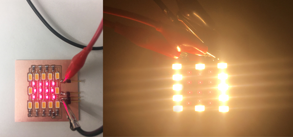
Testing the LED Board--it works!
The next step was to program one of the touch processor boards. I hooked up the red side of the electronics from power distribution to LED board, and sat down with Anthony to start working through getting the code on track. When we tried to program the touch board with initial, basic blink code to test that everything in the setup was working, we got an error message saying that the ATTiny44 processor couldn't be found. We checked connections--everything was fine. Anthony wanted to test to see if it was the same error one would get if you unplugged the programmer completely from the touch processor, and it was–the ATTiny wasn't being recognized at all. We looked for shorts with a multi-meter, and everything checked out. Perhaps there could be something weird going on with that particularly ATTiny44, which sometimes can happen? Luckily, I had the other processor board meant to run the white LEDs. We tried programming that, also with the same results.
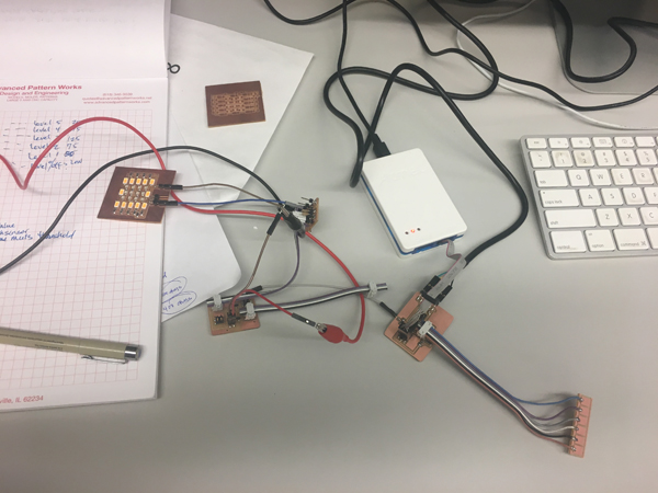
Tryng to program the ATTiny on my touch processing board
Anthony took a closer look at the design of my board, to see if there was an error in the design that would have prevented it from programming. He had questions about a few areas, namely not having a VCC connection on the 2x3 header, but this had been left unchanged from the previous touch slider board I had fabricated earlier this semester, and programmed without issue. The only major changes between the two boards I made was downsizing the number of touch pads in order to free up pin 7 to connect to the LED board, and adding a 2x2 and 2x3 header connections to the power distribution boards and touch pads respectively. Because the touch procesor board would be powered in this way, there was no need for a VCC connection at the FTDI header, so this was also removed. Anthony wasn't able to spot anything else he felt would causing an issue.
We asked Alexandre to come over and take a look, and to offer his oppinion. He also checked the board for shorts, and found everything was fine. He had the same question at first about the the 2x3/VCC connection, but wasn't able to see where there could be an error. Earlier in the day, another student had a similar issue, and was getting the same error with a new, fresh out of the box, Atmel Ice programmer he was using. Subsequently, Anthony and he discovered that the new programmer he had grabbed wasn't working at all, and that his processors were totally fine. Anthony thought there might be a chance that this was the same bad processor left in EECS by accident, so we switched to another, new Atmel Ice to be safe. Same error. Could it be a batch of bad Atmel Ices? The next step was to get another board, that we knew and been programmed in the past, and to try and program that using the same Ice; if it returned the same error, it was probably another bad Ice; if it was able to be programmed, I had two big problems on my hands.
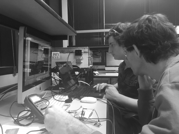
Anthony & the Alexandre helping to troubleshoot
Unfortunately, it was the former, and the test board programmed without a hitch. Ordinarilly, this would have been an annoyance, but something that could have been overcome. The board could be refabricated, and tested again, or completely redesigned. With the time remaining though, this wasn't a realistic option. Even if there was enough time, there was no garauntee that it would program. Luckily, Anthony had his Atmel Mega 2560 with him, which Alexandre suggested would be a more plausible fix; this would give a reliable processor, and we could use this in order to have a version of my project functional for the final presentation the next day. Alexandre and I sat down, and started to reconstruct my processing boards. It was time consuming, but really interesting to see an entirely new process for making circuits (which also required needing a breadboard). I was surprised how much I understood after learning all that I have this semester.
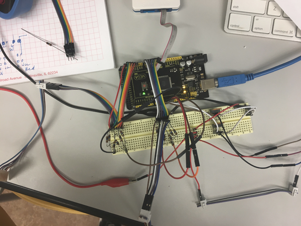
MEGA saved
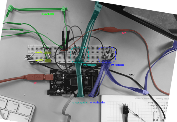
A mess to the untrained eye (me)... here are the macro connections
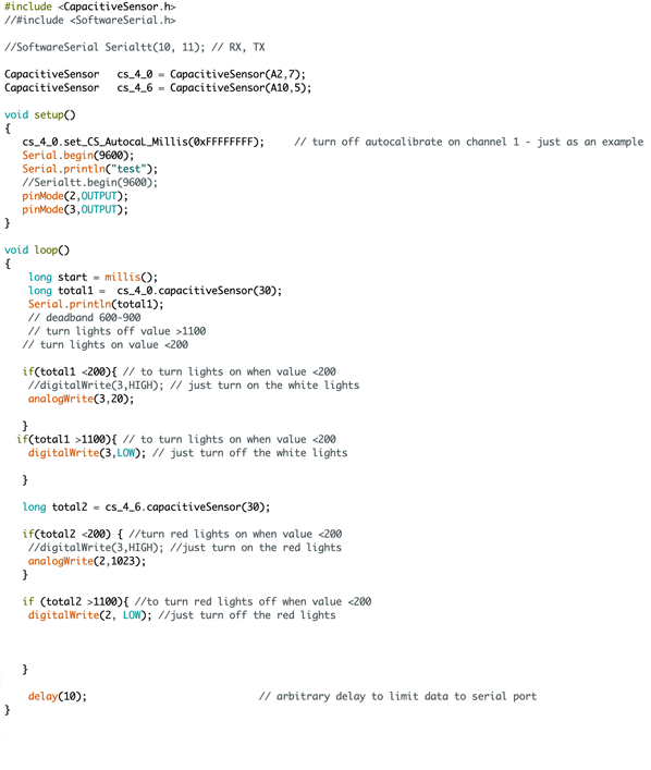
In the end, I was able to program the Mega successfully with the following Arduino sketch, which turns on and off the white and red LED strings separately, and also uses PWM to balance the lumens between to the two color channels (red: 1023, white: 20).
And finally, the whole thing up and running! A special shout out to Anthony & Alexandre for their epic help at the end.
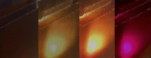
Color shift: off–warm white–mixed–red
Final Questions
What does it do?CastLight uses capacitive touch to turn on and off red and white LED color channels in order to create various lighting effects.
Who's done what beforehand?Capactive touch activated lighting has become a standard in the industry, and is easily found today everywhere from high-end showrooms to Ikea. In the Fabiverse specifically, several projects were particularly relevant and informative as I was working on developing my own, but this is by no means an exhaustive list of all touch capcacitive projects that have come previously, lighting or otherwise:
Akash Badshaw, FabBlaster
Mario Leinonen, LED Lamp
Eva Blsakova, FabLux
I designed the light's housing (shade and base), and well as the majority of electronic boards. The touch capactive boards were redesigned to fit my project's needs, and based on Akash Badshaw's capacitive touch slider.
What materials and components were used? Where did they come from? How much did they cost?
Materials
Smooth-On PMC-476, 3lbs
Price: $36
Source: Renyolds Advanced Materials
Styrene Sheet, 8"x10" (x5)
Price: $4.69
Source: Dick Blick
Prusa PLA Spool
1kg, 1.75mm
Unit Price: $20.99
Source: IDC
Electronic Components
LED LM561C White, Warm 3000K
SPMWHT541ML5XAVMS0
Unit Price: $0.12 (x12)
Source: Zach's Stash
LED RED CLEAR 1206 SMD
160-1167-1-ND
Unit Price: $0.13 (x12)
Source: Fab Lab
CAP CER 1UF 50V X7R 10% 1206
445-1423-1-ND
Unit Price: $0.07 (x2)
Source: Fab Lab
MOSFET N-CH 30V 1.7A SSOT3
NDS355ANCT-ND
Unit Price: $0.26 (x2)
Source: Fab Lab
IC MCU AVR 4K FLASH 20MHZ 14SOIC
ATTINY44A-SSU-ND
Unit Price: $1.18 (x2)
Source: Fab Lab
IC REG LDO 5V 1A SOT223-3
NCP1117ST50T3GOSCT-ND
Unit Price: $0.45 (x2)
Source: Fab Lab
RESISTOR 0Ω 1-4W 5% 1206 SMD
311-0.0ERCT-ND
Unit Price: $0.005 (x3)
Source: Fab Lab
RESISTOR 499Ω 1-4W 1% 1206 SMD
311-499FRCT-ND
$0.01 (x9)
Source: Fab Lab
RESISTOR 1MΩ 1-4W 1% 1206 SMD
311-1.00MFRCT-ND
$0.01 (x6)
Source: Fab Lab
RESISTOR 10kΩ 1-4W 1% 1206 SMD
311-10.0KFRCT-ND
$ 0.01(x4)
Source: Fab Lab
2x3 HEADER CONNECTOR SURFACE MOUNT
609-5160-1-ND
$0.66 (x9)
Source: Fab Lab
2x3 HEADER CONNECTOR SURFACE MOUNT
609-5161-1-ND
$0.60 (x4)
Source: Fab Lab
1x6 SMT RT ANGLE MALE HEADER
S1143E-36-ND
Unit Price: $0.55 (x2)
Source: Fab Lab
1x1 SMT RT ANGLE MALE HEADER
S1143E-36-ND
Unit Price: $0.09 (x7)
Source: Fab Lab
CBL RIBN 10COND 0.050 MULTI 50'
MC10M-50-ND
Unit Price: 38.07
Source: Fab Lab
Total Project Cost: Approximately $77
What parts and systems were made?
All of CastLight's physical housing and electronics systems were fabricated from the 'raw' materials listed above.
What processes were used?This project utilized milling, casting, 3D printing, soldering, as well as manual fabrication techniques (cutting, sanding, etc...)
What questions were answered?
For me, the most important question I answered was Can I actually make this? Looking back, even to the middle of the semester, it was sometimes hard to imagine how all the skills I was lacking would eventually fall into place.
How was it evaluated?
There are a lot of successes, mostly relating to the overall fabrication and final aesthetic presence of the project. I was very pleased with the play of light and material in the end. Clearly, some areas of the project didn't reach their potential, or the vision I hold for it. Most importantly, the failure of my processing boards to program was a huge disappointment (and slight mystery still). Having to rely on Anthony's MEGA for the presentation was not what I would objectively label a success. And at the same time, I'm proud that I was able to push through that major setback, and to have a functioning proof of concept for the presentation. Getting my project to this point, even with the work that still remains, has given me the skills and foundation I need to succesffully finish it to a level I will consider fully successful.
What are the implications?
This isn't, by any means, a ground breaking project. It's certainly not a freak'n wind tunnel for advanced research. It's an object, that hopefully, adds a little beauty to world. But personally, the implications are substantial. Though a tough road at many points, I've learned an incredible amount, specifically through the production of the final project, and having to integrate all I've absorbed through the course of the semester. I did things in this class I'd never considered doing before, and I loved doing things I never anticipated I would love.
When I was designing the LED board, I had a flashback to elementary school, where in third or fourth grade, we studied basic parallel and series circuits for a few weeks in science, spending our days learning how to light up strings of incandescent bulbs. I'd forgotten, until very recently, that doing this, was one of my favorite things in school growing up. As Neil has said many times, the class actually starts now. I look forward to what's to come.