Final Project
Introduction
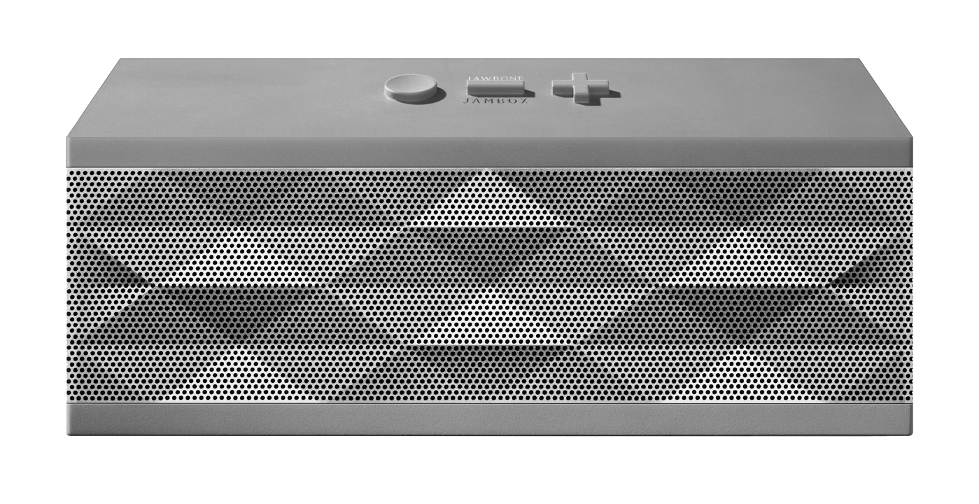
When I started this class, I had two Ideas for final projects: an ultrathin boombox and a boombox quadcopter. As I progressed through the class I learned a lot about the time it takes to produce something of high quality and realized that the quadcopter would simply be too complicated to do well within the scope I had. That left me with the thin boombox and here again I realized I would have to make a compromise, essentially functionality at the expense of thinness. Instead I decided to modify the concept a little bit and set out to make a bluetooth boombox, similar in function to products like the Jawbone Jambox. This would give me the opportunity to create a cool box for the speaker using some of the mechanical processes we learned in class and also explore some interesting electronics production. Read on more to find out about my journey to make this and how I (hopefully) accomplished this in 2 weeks.
Previous Work
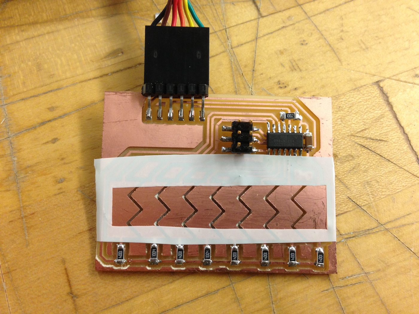
Since the Input Devices week I had started working towards this bluetooth speaker. I started by exploring potential volume and other control systems, and ended up making a touch pad to scroll the volume. I may not end up using a continuous volume control (using +/- buttons instead) but in the final project I intend to employ tactile buttons of some sort. My experience from that week will come in handy in producing these controls on the final box.
I continued prototyping pieces of my final project in the Output Devices week where I worked on an amplifier circuit. Although I didn't manage to get my board from that week working, I did eventually figure out how to correctly wire up those amplifiers and how to debug when they are misconnected. I don't plan on using the same amplifiers in the project but I became much more familiar with amplifiers and speakers and that will come in handy in the final.
The final piece of prep work I did for the final project was in the Networking and Communications week where I decided to build a board to experiment with the bluetooth module I wanted to use. Again I failed here, but I learned a lot and planned on making my second version of the bluetooth board much simpler. Part of what I learned here was also to reduce my scope a little bit and to have a backup plan. If I can't end up getting bluetooth working I will default to a simple auxilary jack so I can still have something to show for myself.
Planning
I started working in earnest on the final project after Thanksgiving break, and have scoped out all of the parts of the project and what needs to be done. I basically broke the project up into two main sections: the electronics and the enclosure.
I am hoping to have the electronics situation decided by the December 9 so I can spend the rest of the time working on the enclosure. The first big question about electronics is whether or not I will be able to use bluetooth. While I am waiting for other parts to arrive, I still have one more bluetooth module and I plan on using that time to build a much simpler board than the original I tried to see if I can get a good connection established. I think part of the problem with the first version may have been the general hackiness of the board so I am going to try to keep things simple. After figuring out the bluetooth situation (or failing and moving on to simple aux jack) I will work on getting the amplifier circuit for the speakers up. Finally, I will build out the controls system and then hook everything together to get an end to end system working.
I will spend the next week working on the enclosure itself. I am hoping to have some kind of cool geometric pattern on the enclosure like on the Jambox so I will take some time to design something cool. I plan on molding the box so I will also need to buy some plastic to cast with that has a nice matte texture. Finally I plan on making the speaker grill out of a piece of aluminum which has the holes machined with the water jet. I haven't used the waterjet before but hopefully I can get enough help to make this a reality.
Parts
One of the biggest time factors involved in the project is whether or not I have parts on hand to work with, so I have ordered all of the electronics components I think I am going to need. The important ones are listed below.
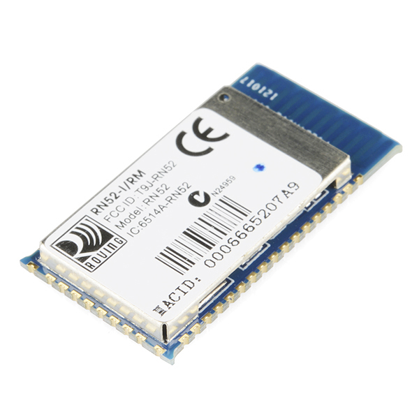
- The RN52 Bluetooth Module: This should handle all bluetooth communication to the phone, ~$25
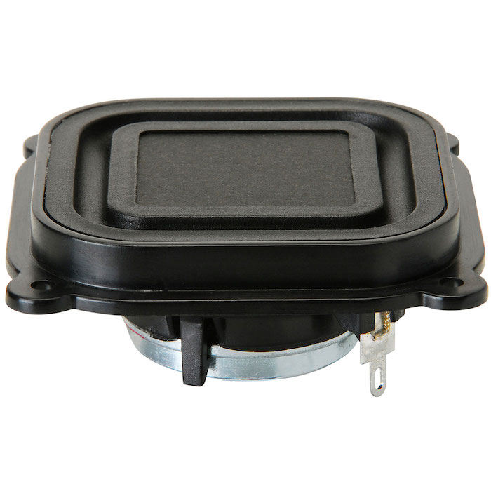
- The BMR12 Full Range Driver: Some really powerful little speakers that should pack a good punch, ~$6/each
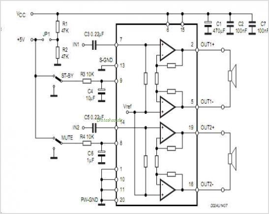
- The TDA7297d Amplifier: A simple amplifier that should output 10Wx2 for 8 Ohm drivers like the ones I've got, $4.5
I also ordered some of the simpler parts I might need like auxilary jacks just so I don't have to wait on multiple digikey orders.
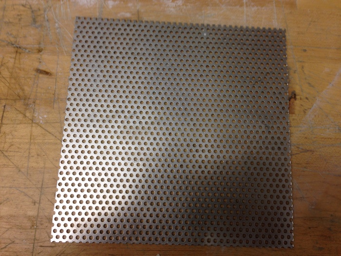
For the enclosure I had the idea of making a matte plastic box and covering the front piece with perforated aluminum for a speaker grill. The main choice to make here was what kind of casting plastic to use and how to color it. I took a trip to Reynolds where they showed me a bunch of different materials that could all be colored. I was particularly drawn to Smooth Cast 300 which dried white and was colorable to give that matte finish. I bought that and some purple coloring for just under $40. I also bought a variety pack of Perforared Aluminum Sheets from Amazon which would allow me to see which hole size would work best, these were about $10.
Overall that brought the cost of materials to just under < $100 if you consider the marginal cost of the other electronics. This is a great price range for something like this considering that Jambox started with a multiple hundred dollar price range and has only now pushed down to about $120.
Update for December 11th
Electronics
I spent this next week working on getting the internals of the bluetooth boombox working. I'm happy to report that over the course of the week I was able to get the bluetooth module working, as well as all of the other circuitry I am going to need for the final. This means that I can focus my last week on the mechanical components of the system. Read on to learn more about my successes with electronics this week.
Bluetooth
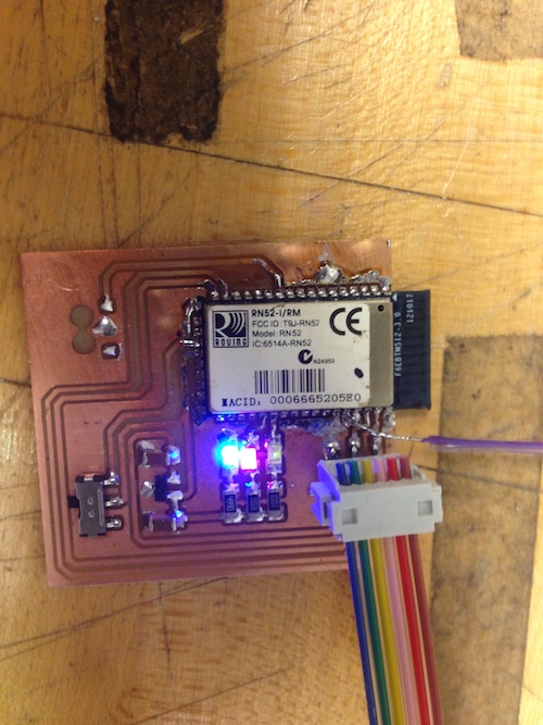
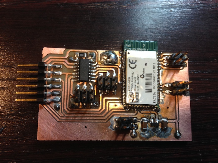
The first thing I set out to do this week was continue my work on getting the bluetooth module working. I was unable to get it working in Week 12 because something with the configuration of the module was causing it to repeatedly crash and I assumed it was a power error. In order to investigate if it was just a voltage error I built an even simpler board than my first pass and connected everything. Low and behold I had the same problem! I eventually figured out that it was because I was grounding the negative terminals of the speaker output. Apparently the bluetooth module expects the output to be driven differentially instead of in a bridged configuration, so I severed the connection to ground and got everything working correctly!
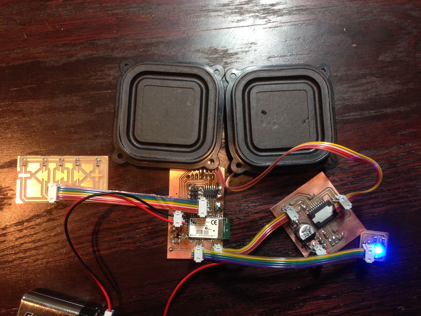
FabBlaster Main Board
From there I went on to making the main board for the project, knowing that I could now correctly communicate with the bluetooth module I set about to getting a microcontroller that would be able to send the module commands for things like volume and track control. I was following the RN52 Command Reference Guide and found that I could accomplish most of the controls with a basic serial communication to the module.
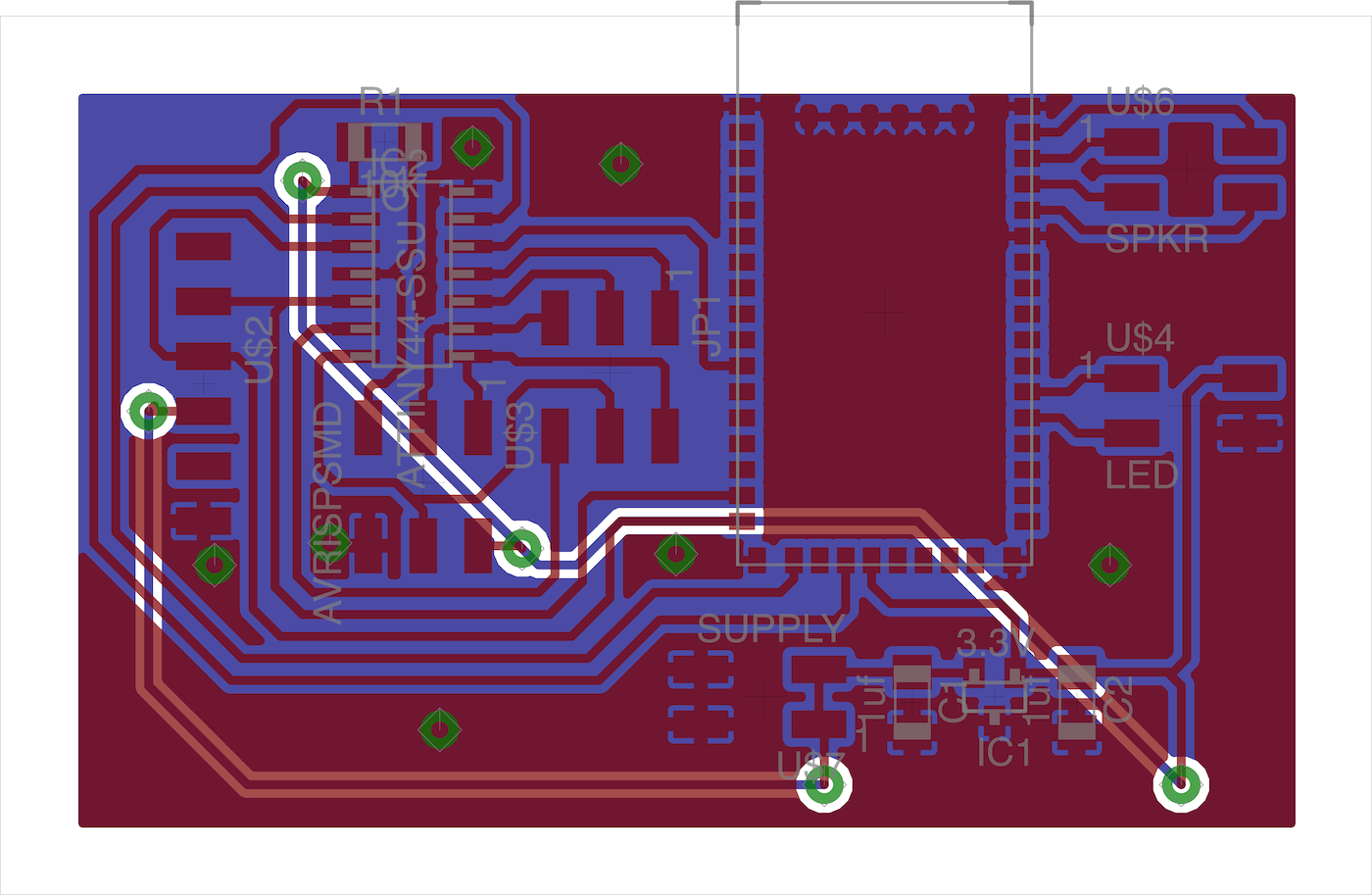
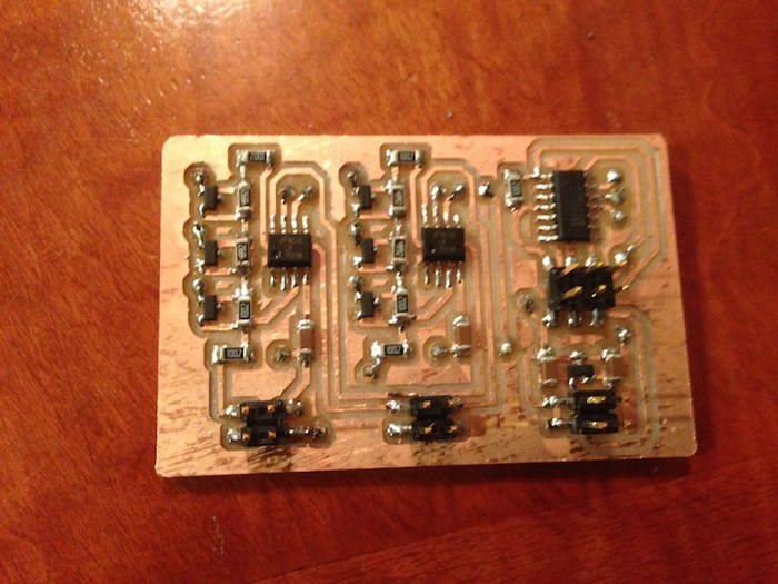
On this simple board I had an ATTiny44 for the communication with the RN52 bluetooth module and connectors for power, the led indicator, the speaker output, the controller board, and ftdi + isp communication. The ATTiny44 sends ASCII commands to the bluetooth module which correspond to actions like "play, pause, etc" that allow me to control the phone using A2DP/AVRCP bluetooth protocols.
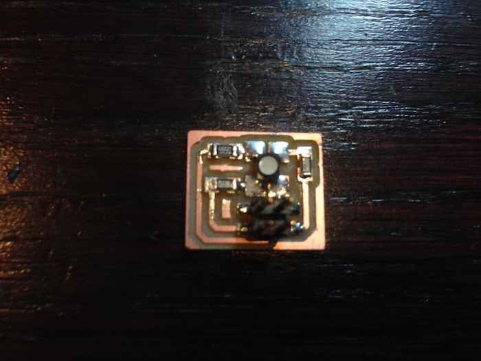
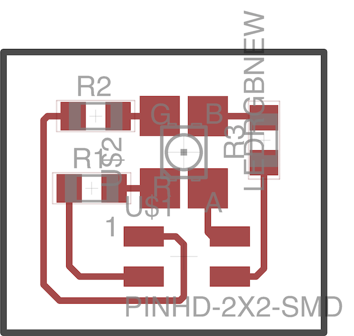
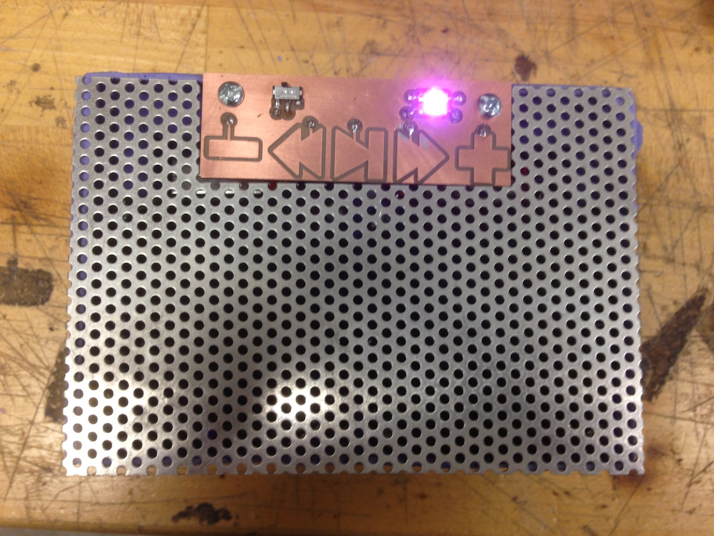
The bluetooth module also has a simple LED output interface so I made a simple 3 color led board attachment which I hope to put on the outside of the box as an indicator of status. Fortunately, in using these modules I have found that the LED board is also extremly helpful in debugging problems. On the RN52 module does so much of the heavy bluetooth lifting for you and makes it extremely easy to interact with, on the other hand that produces a great deal of complexity that makes it difficult to debug problems. The LED's have helped because I have been able to see how the chips decay and recognize that as a burnt chip.
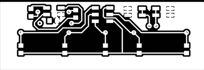
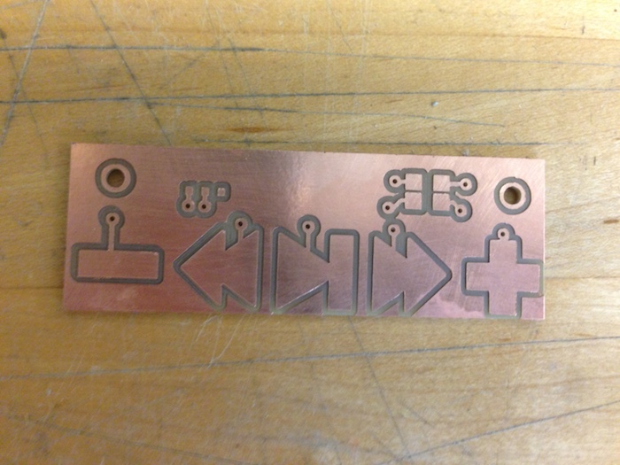
Controller Board
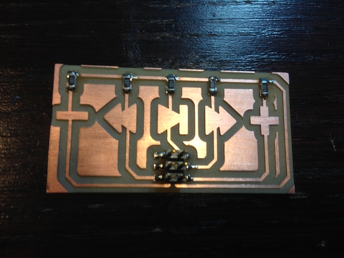
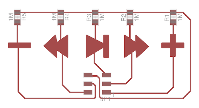
In the final version I want there to be a panel on the front of the box that has buttons to control it. I liked the way the capacitive buttons worked in my input devices project so I am planning on using a larger version of that. In the interest of focusing on the software and more complext modules I made a demonstration and testing board which allowed me to test each of the commands.
Amplifier Board
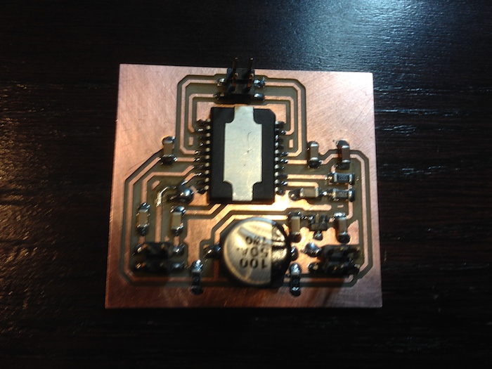
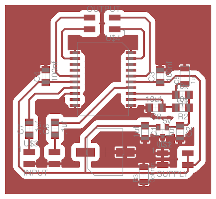
The next step was the amplifier which I built fairly quickly but also realized that because it was a dual-bridge amplifier I would have to isolate the ground from the ground of the bluetooth module. I first seperated them and got everything working, then tried to see if I could connect them and unfortunately blew another module! This was helpful in some ways because it confirmed my earlier suspicions and the modules blew much faster because of the voltage being amplified. This also means that in the final version I will need to seperate the power stages so that I have an independent source for the module and the amplifier.
Conclusion
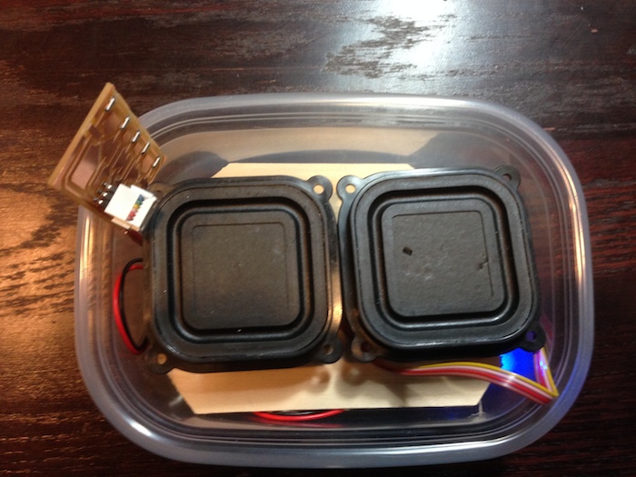
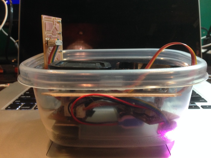
In order to make carrying easier and to play around with the functional speaker I put everything in a tuperware and used a piece of balsawood to seperate the speakers from the components. I had a lot of fun playing around with it when everything was finally working!
You can download both the software files and the design files from below. These will be updated with the final version when the project is complete.
Update for Final
Enclosure
Design
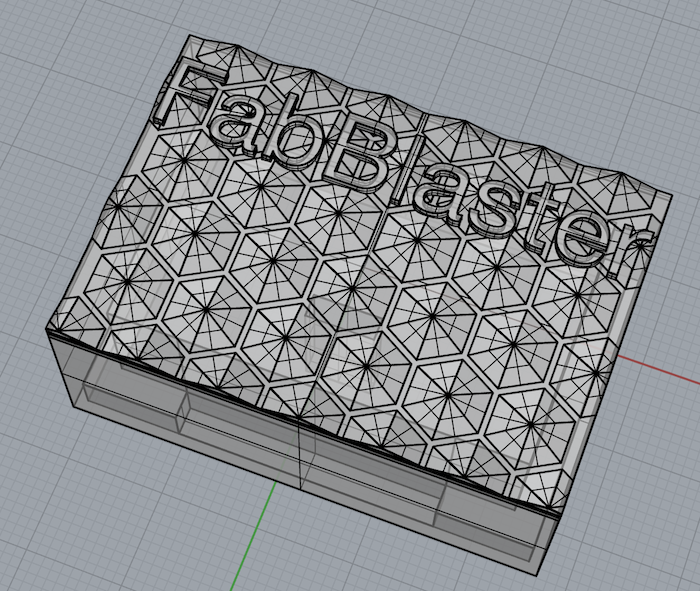

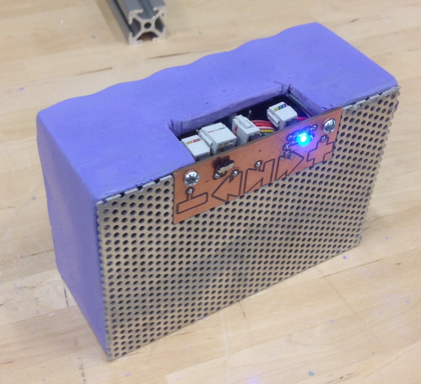
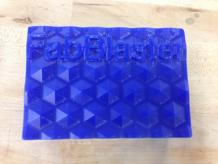
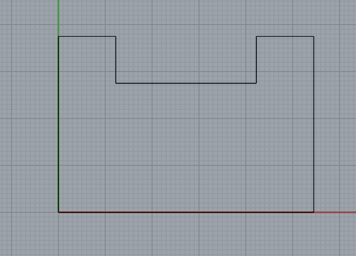
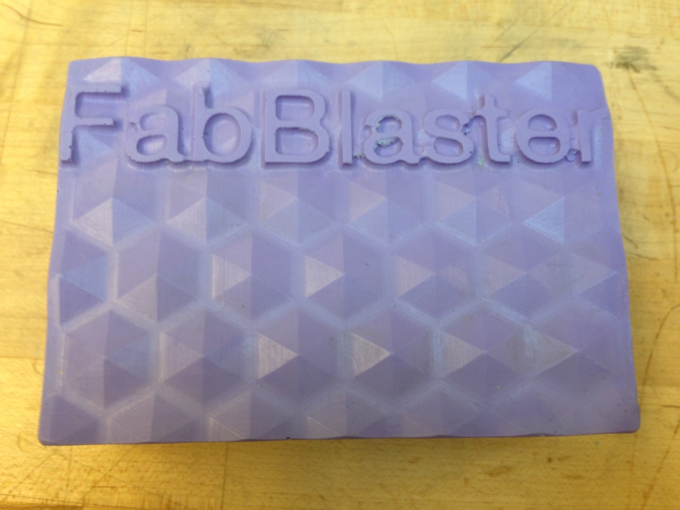
For the enclosure I really didn't need much more than a box with one face open. I did, however, want to cast something with a cool texture so I decided to make a honeycomb pyramid pattern on the closed big face of the device. I also cristened the case with the name of the box: the FabBlaster which is a mashup of Fabricated and Blaster because it (hopefully) blasts sound! I made the dimensions about 6" x 3.5 " x 2.5" which is a great size for being held with either one or both hands.
Mold-Making
I now needed to make a two sided mold for my design which I could cast oomoo into and then eventually cast the plastic into that. I went with a mishmash of processes to best appeal to the geometries of the different sides of the box. The bottom face consisted of mostly a large block with an intricate surface pattern. I milled the outer surface of the box out of a block of wax, with a very fine step over to get a great surface finish. I then built a small wooden box around it so I could pour oomoo around it.
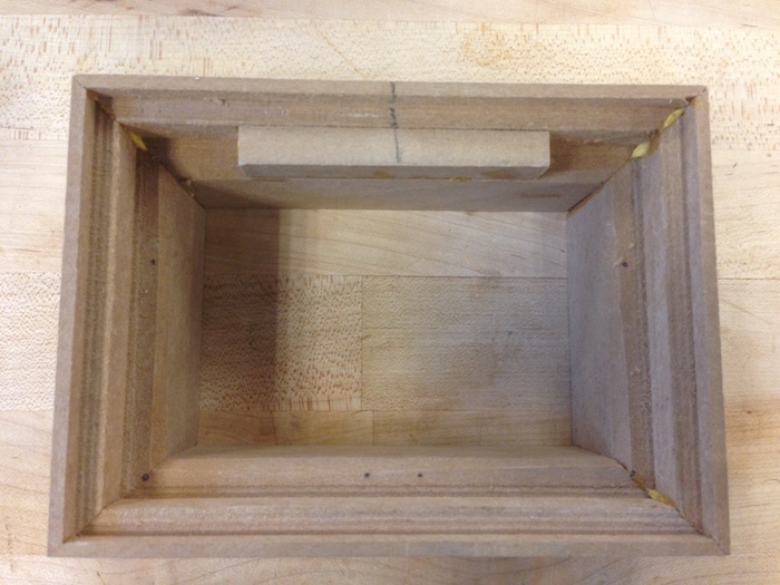

The top face was a bit trickier since it was little more than just the inside walls of the box, with an indent for the speakers to screw into. It didn't make sense to remove so much material with the mill so I instead built the box from pieces of mdf the old fashioned way. Big shout out to Chris Dewart who helped me through that whole process and helped me get a good mold. I also built in a pyramid pour hole so it would be easy to pour and easy to break off.
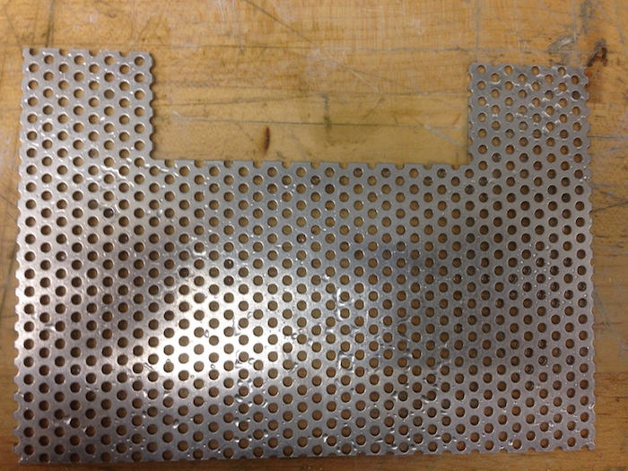
Front Face
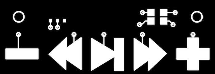
While the oomoo was setting I went about making the last few pieces I would need for the final piece, essentially all the stuff to put on the front face. I wanted to keep things simple so I decided to go with a metal screen made from aluminum cut on the water jet and a circuit board for the capacitive buttons. On this board I also put the power switch and the indicator led to tell me the status of the device at any given time. These two components went off pretty well but I was extremely happy to be able to use the water jet at least one this semester, even though the cut was very simple.
Casting
The final piece in building the enclosure was actually casting the plastic. The smooth-cast has a pretty quick set time but that also means you can see how your part looks in about 10 minutes. Everything went pretty smoothly until I basically cast it with the top and bottom upside down with respect to one another. Good thing the cast was quick because I just flipped the molds and made another!
You can download all of the files I used to design these outer components here
Conclusion
Putting it all Together
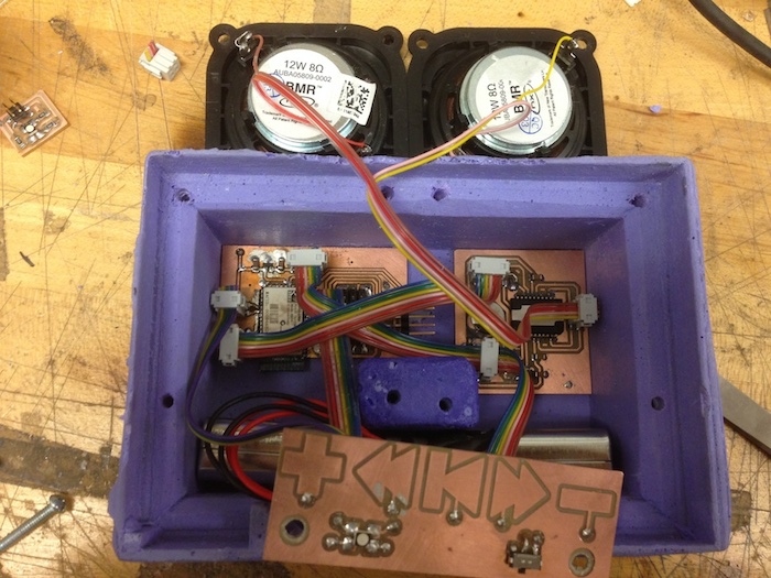
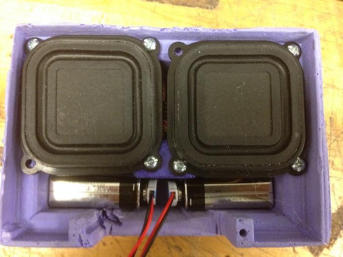
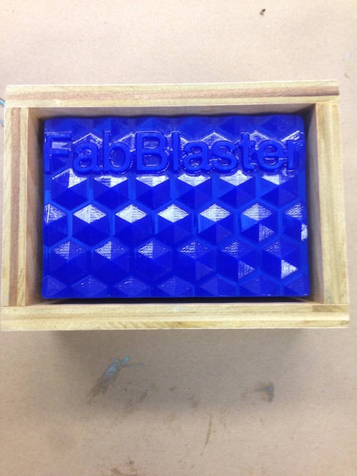
All that was left to do now was drill some holes and put it all together. I also didn't account for the space required by the connectors so I had to cut out a bit of the box but on the other hand it have me a compartment to change the battery through. I started by gluing down the main electronics with hot glue to the bottom of the box. Then I put the speakers and batteries in. I finished up with the screen and control board and I was off and running!
Lessons Learned
There were a couple of main take aways I took from this project, mostly from the places where I ran into a lot of trouble and needed to spend more time.
Multiple Revisions: I learned that I needed to budget more time for building multiple revisions or drafts as I go along. Despite spending a lot of time in the design stage, things are always going to change as you move into production so I learned that its really more helpful to spend time constantly revising and changing the design based on feedback from production.
Consider Power Electronics: I ran into a bunch of problems from the get go with running the amplifier, bluetooth board, and the speakers and these continually plagued me throughout the project. Eventually I realized all of these things stemmed from not considering the power electronics of what I was doing. If I had learned more about that and kept that central to my design I think I would be able to do a much better job.
Patience: This goes along with the multiple revisions thing but I really learned you need to be extremely patient and cautious with the way things are actually made. As a computer scientist I'm used to making something, running it, and watching the errors pour out. Then I can just go fix the bugs and run it again, no harm done. In the world of physical parts its not so simple so living by the mantra of "measure twice, cut once" is a critical component of success.
Wrap Up
Overall I'm extremely proud of the boombox I was able to produce. It's quite loud and exceptionally nice feeling in the hand. The weight and textures make it feel unique and its actually really useful! I hope you enjoyed following me this semester as I learned How to Make the FabBlaster.