For my final project, I intend to construct and automate one of Albrecht Duerer's lesser known drawing machines ca. 1525. Though Duerer is most famously known as a Renaissance artist, he was also an early contributer to visual perspective and mathematical scholarship through his drawing instruments. His interests in human proportions and movement led to two significant drawing machines in his late career, the Snail (die Schneck), the Spider (die Spinne), and the Snake (die Schlange). It wasn't until recently, while whatching a lecture by Bernard Cache titled, "Duerer - Vitruvius - Plato. Instruments of Thought" that I became aware of the lesser known instrument, the Snake. While only a diagram of this instrument exists, we can clearly see "dials" and "rods", which free the instrument from planar movements, giving it the range to simulate movement in 3D space, which he calls the serpentine line. And although many hypothesis suggest why this instument was drafted its purpose is still unknown.
In his more famous perspectival devices, the eye of the observer plays a fundamental role, however, the Spider and the Snake were constructed to generate points and lines. The Spider (Fig. 01) produced 2-dimensional lines (Fig. 02) and the second, the Snake (Fig. 03) is thought to be used to draw a variety of lines that Duerer would call a serpentine line.
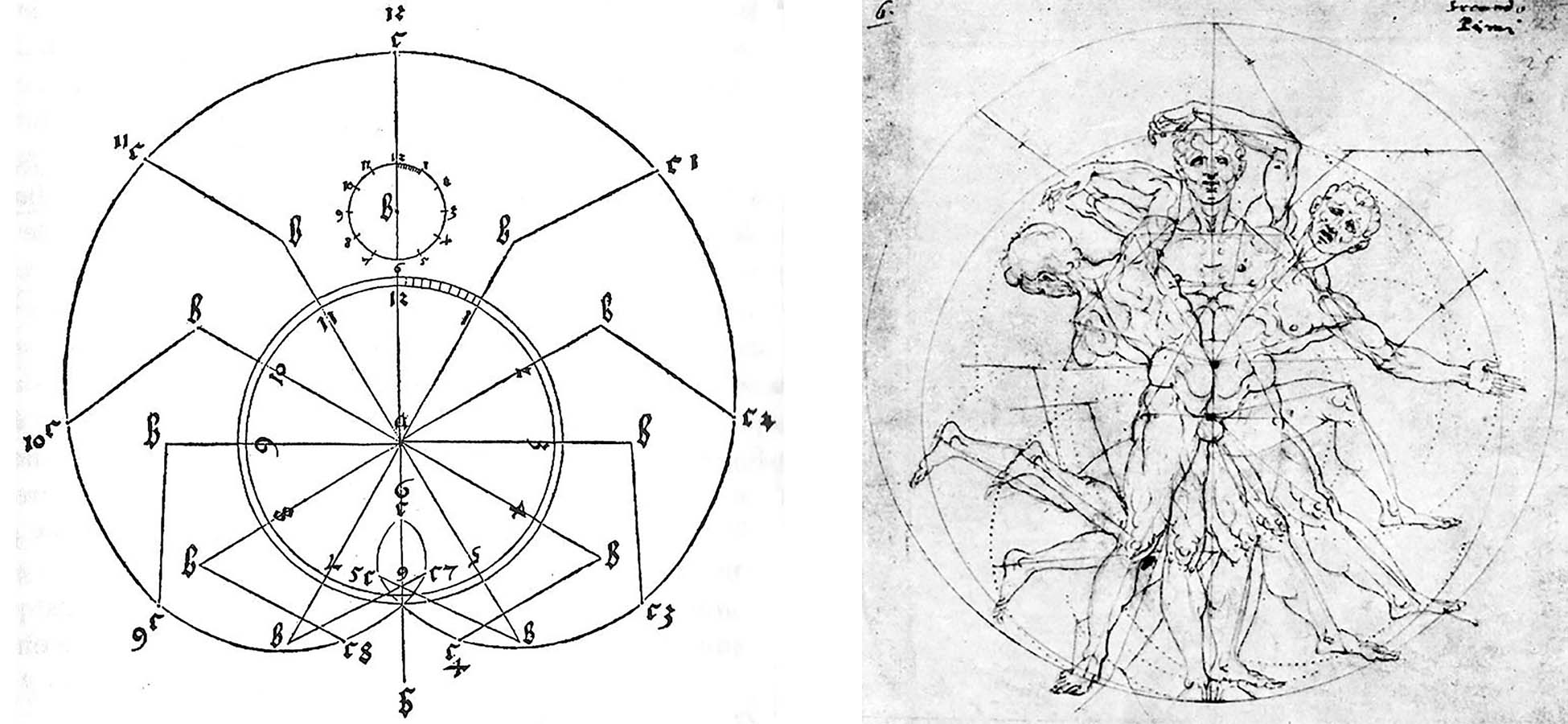
Fig. 01 and Fig. 02
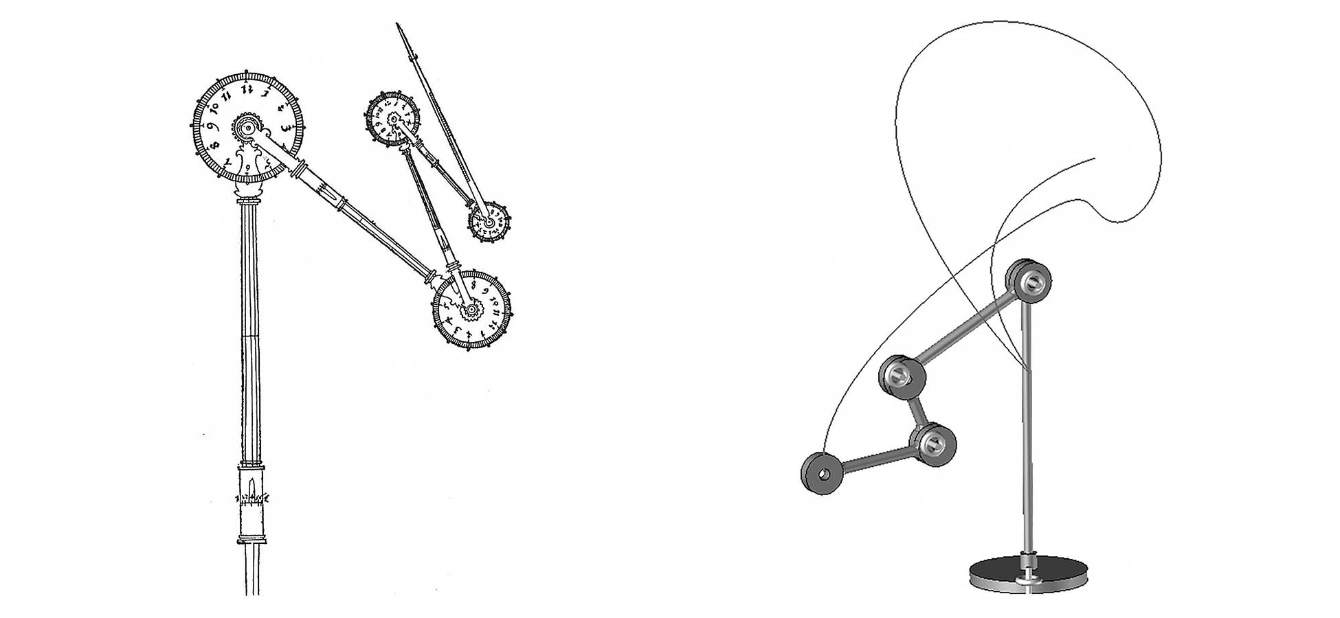
Fig. 03 and Fig. 04
Pictured above is the only record of the Snake instrument (Fig. 03) and a computer model (Fig. 04) Bernard Cache generated in ca. 2012. In these two illustrations you can see the "dials" and "rods" Duerer references in Underweysung der Messung, the book where the original diagram is published. In this text, Duerer describes how to construct die Schlange, an instrument that can be used to draw a variety of lines, the serpentine line (paraphrased by Bernard Cache):
1.) The instrument should be made with few or many dials and rods, according to the intended applications.
2.) The rods shall be arranged in a manner that they can be advanced by degrees and can be shortened or extended.
3.) The rods can be pulled apart or pushed together, also by degree, so that they become shorter or longer.
A formal analysis of these instruments was initially presented by Bernard Cache in 2012 at Cornell University in a lecture titled, Instruments of Thought. Since then, Cache continues to write, lecture, and produce related material on the subject.
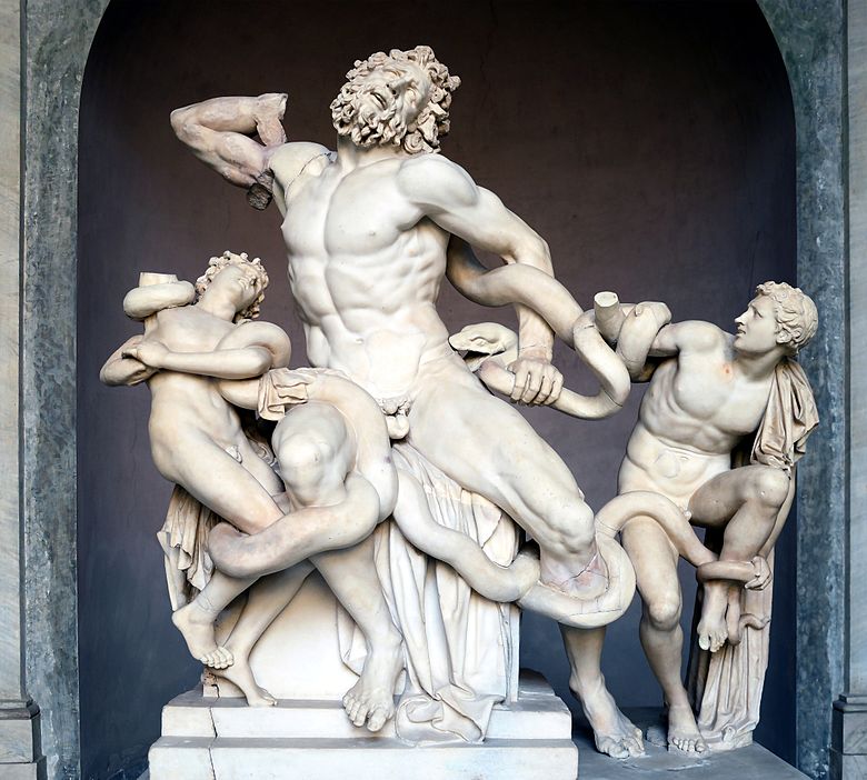
Fig. 05
While the intent of this instrument is still unclear, many have hypothesized that it was used in the fabrication or restoration of sculpture, one example is Lacoon and His Sons, (Fig. 05). Regardless of intent, this tool has the potential to construct non-standard objects with repeatable variation. A drawing instrument that never constructs the same spline twice.
Through the calibration of the dials and rods, the data points relative to the central leader are endless and varied. Unlike many of his other instruments where he includes lengthy notes, and formulas on the instrument’s performance and anticipated results, Duerer, did not show us anything more than a diagram of the Snake instrument. At the time this instrument would have been used to construct what was called 'superior geometry' which simply refers to a line that could not be constructed with a ruler and compass. In other words, a spline putting emphasis on the parametric design and mechanical variations in the 15th century.
Simulation and testing:
To simulate the path of the drawing instrument, I am using Unreal Engine. Fig. 06. A video game engine, which I can use to rig the device to control the direction and speed of each dial and rod.