Week 8: input devices
Skills used: PCB milling (KiCAD and MODs), soldering, and programming (Arduino).
Part 1, Design:
My ambition for this week was to create a 3 axis accelerometer using an ADXL343 that could attach to the end effector of my final project. The purpose would be to understand the location of the arm in space. Then use that information to change the color of the led on the end effector, as it continuously generates splines. This was challenging.
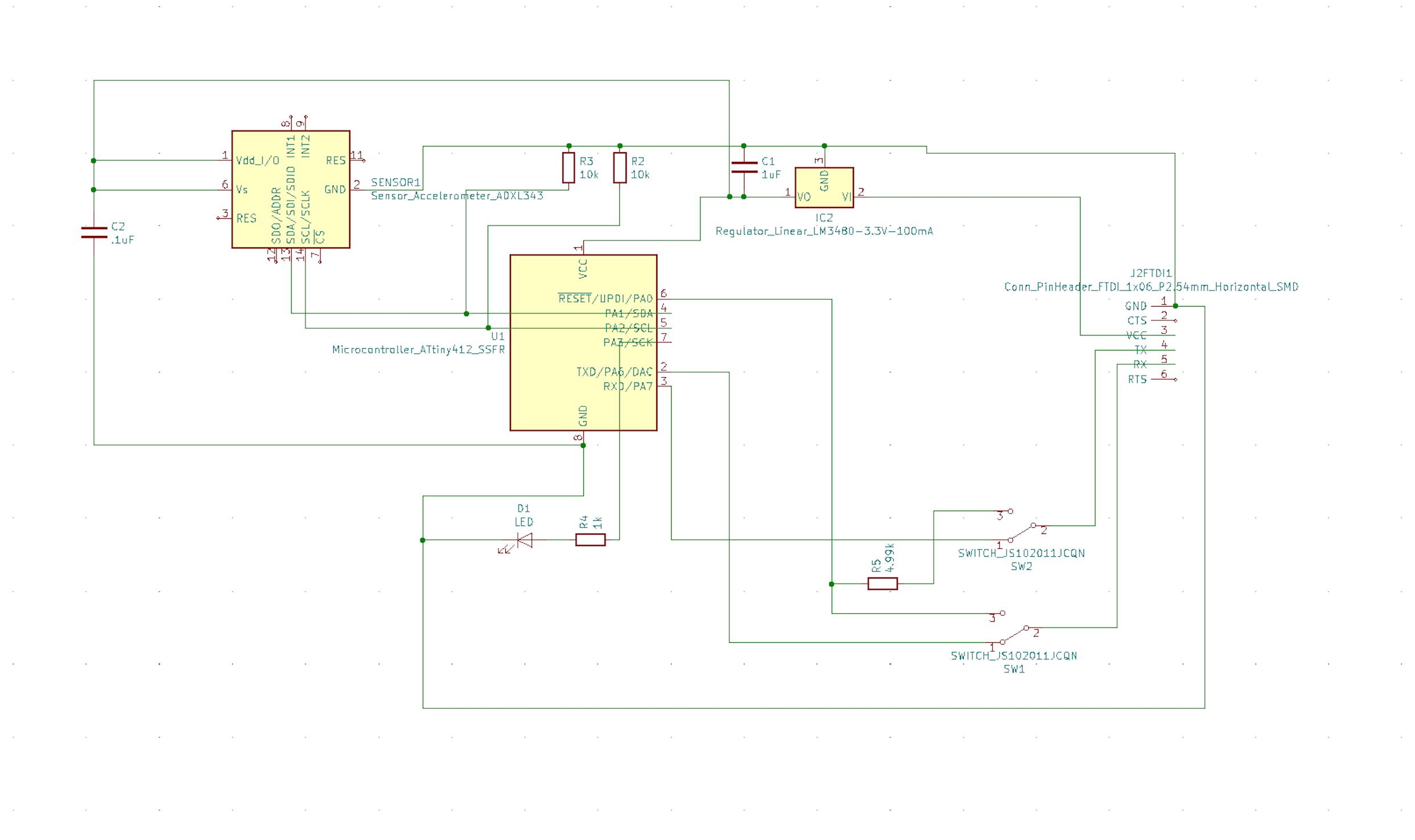
To begin, I referenced Neil's ADXL343 example which uses an ATtiny45, but made a few changes. 1.) I swapped the ATtiny45 for an ATtiny412, which we have in the arch shop, 2.) ommited the 6-pin header, as I didn't think it was necessary, 3.) added an LED to test the board, and 4.) added two slide-switches to between the TX and RX pins on the FTDI cable and the ATtiny412.
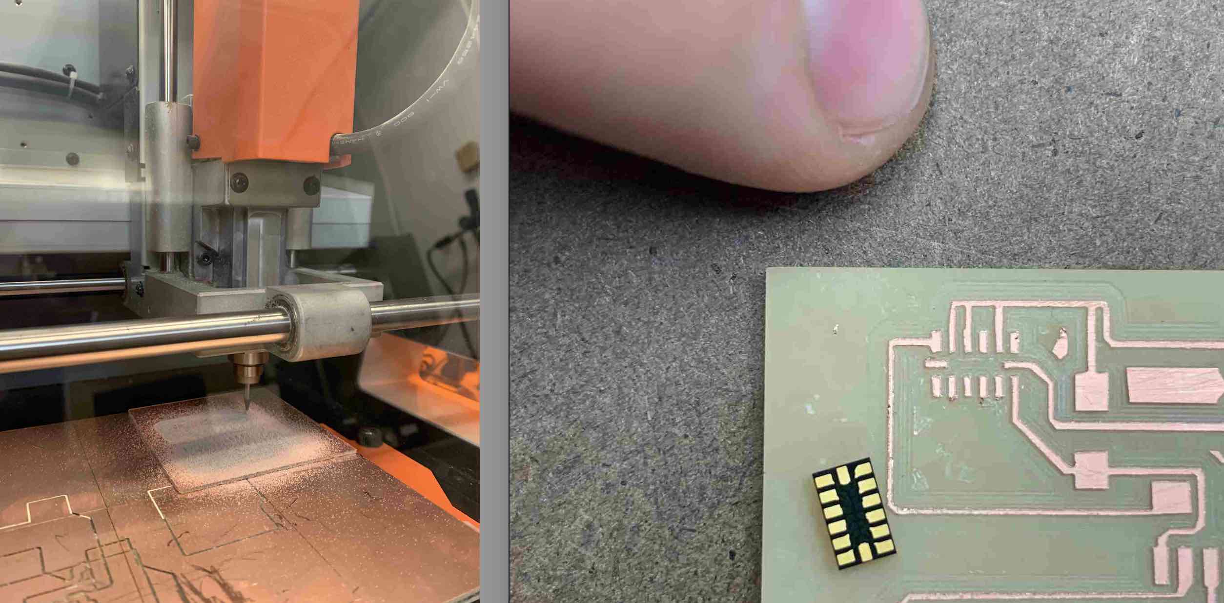
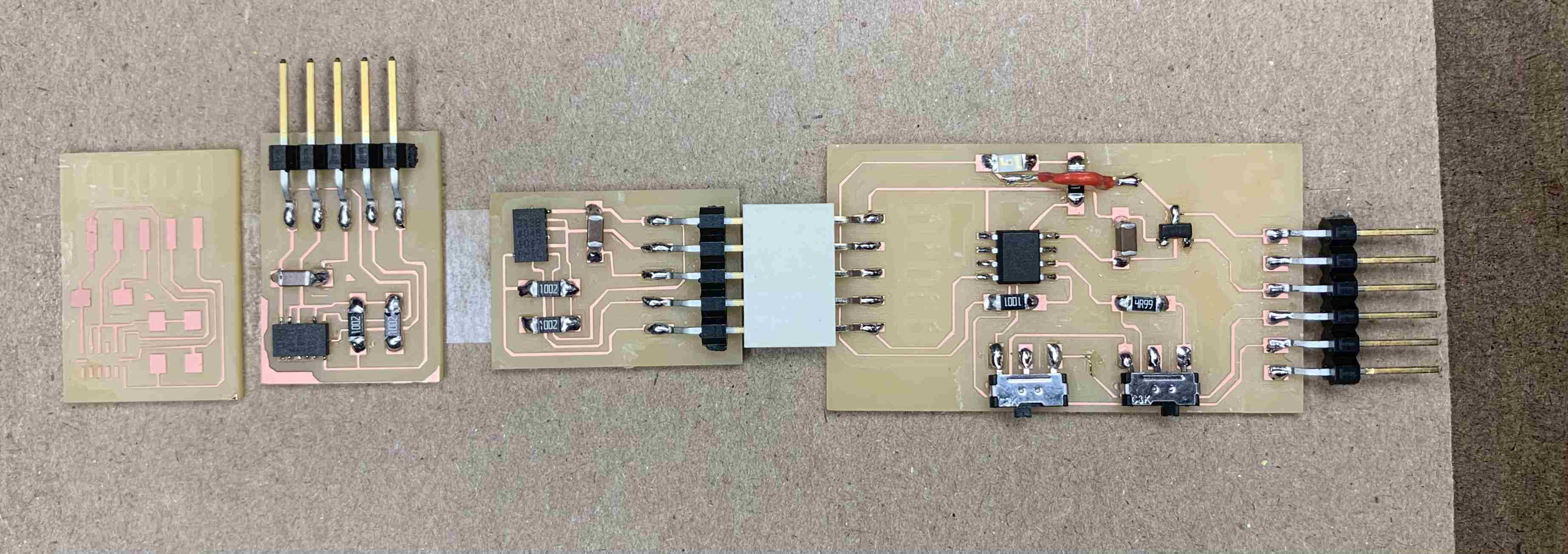
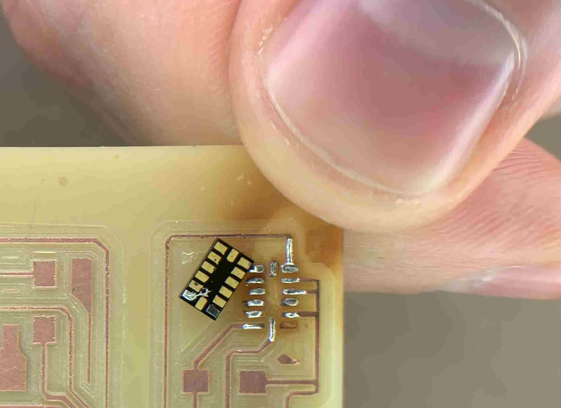
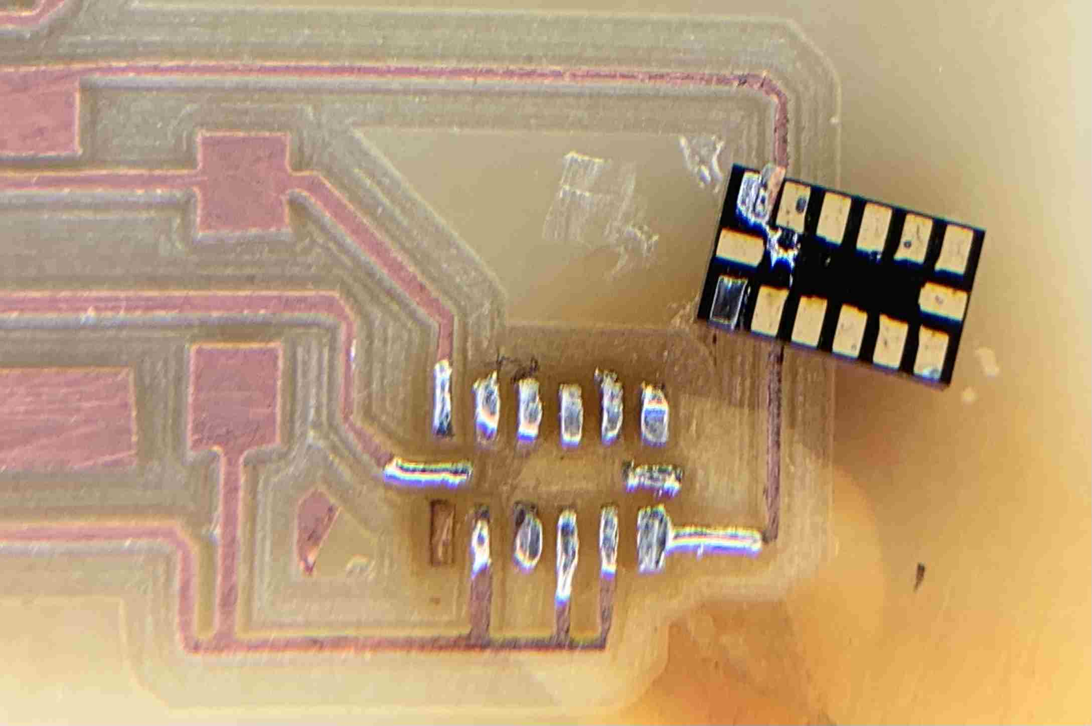
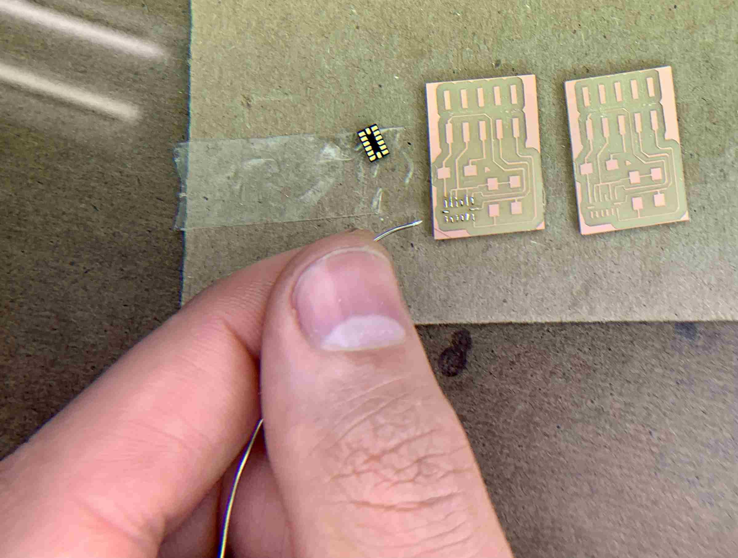
The ADXL343 sensor is very VERY small, and the pads are even smaller, which are hidden underneath the accelerometer. So it is very difficult to ensure that the ADXL343 pins are properly connected to the correct pads. Therefor, after several failed attempts to use the heat gun to (reflow)solder the accelerometer to the PCB, Calvin suggested I use a break out board for the ADXL343. This way I wouldn't have to remill and resolder all my components if the accelerometer didn't work due to a soldering error.
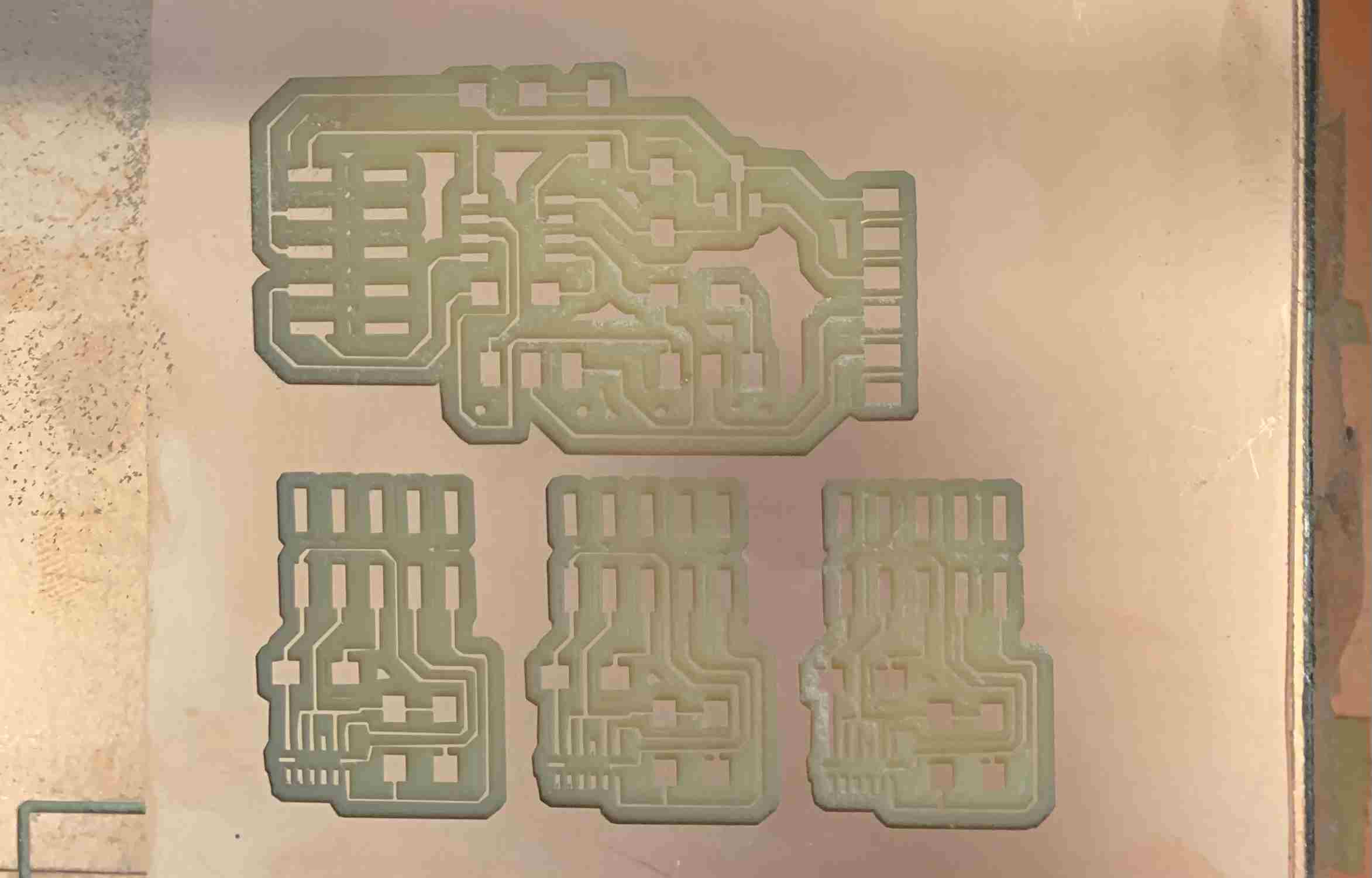
Pictured below is one of the boards that I managed to burn with the heat gun.
Then, I returned to KiCAD and seperated the board with a M/F FTDI 5-pin connector. Here you can see the original schematic and the new schematic with a break out board for the ADXL343.
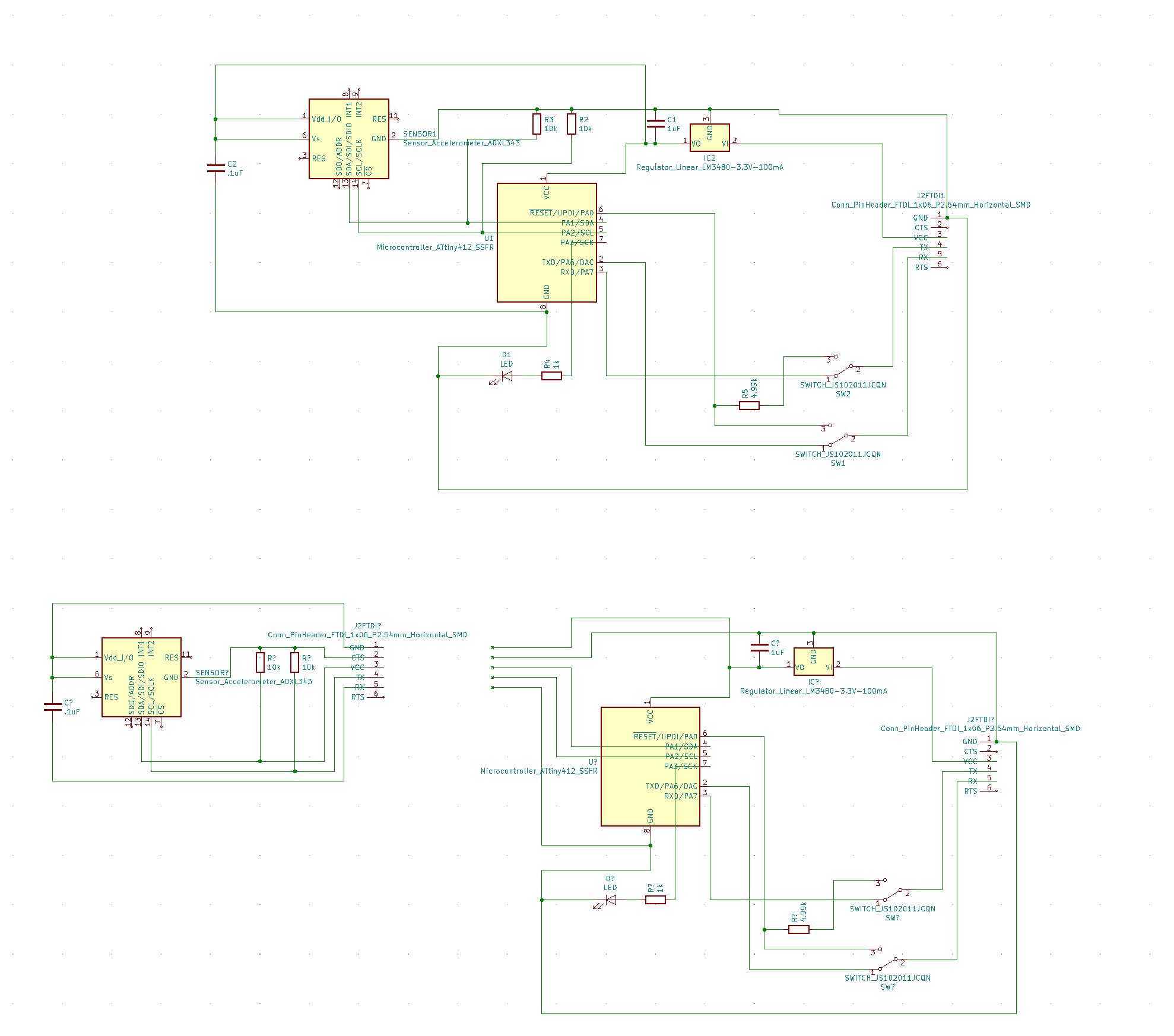
To be sure I had could a successful sensor to test, I set up my traces to have 3 break out boards, which I could use if needed.
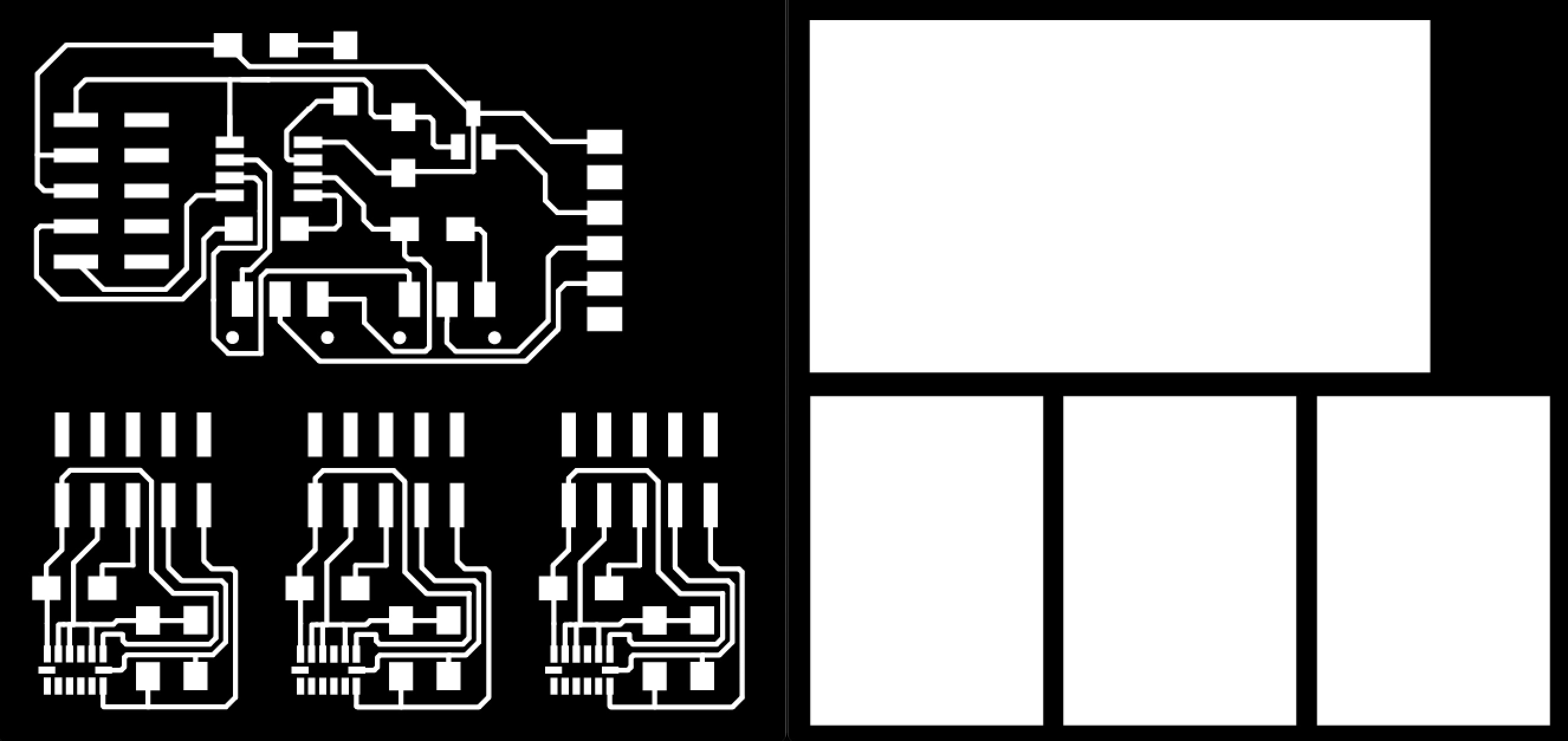
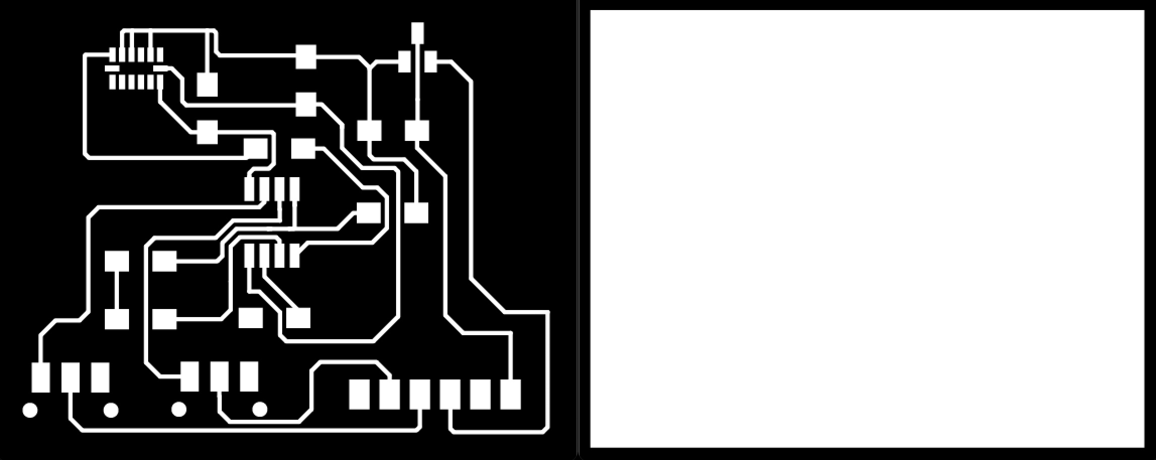
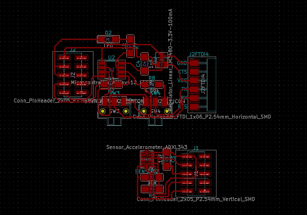
In MODs, I adjusted to the traces to be small enought to seperate the pads of the ADXL343. While this worked to leave a large enough gap between the pads, the traces became very delicate and I ended up having to repair one with a jump wire.

Once soldered, I went to Arduino to test the PCB. While I was able to get the LED to blink, I am still having an issue with the ADXL sensor... I can't spend more time on this PCB this week, but I will continue to work to integrate the sensor into my final project. Stay tuned.