Week 3: 3D scanning and printing
Skills used: 3D scanning (EinScan-SP), slicing, and printing (Sindoh, 3DWOX).
Part 1, 3D scanning:
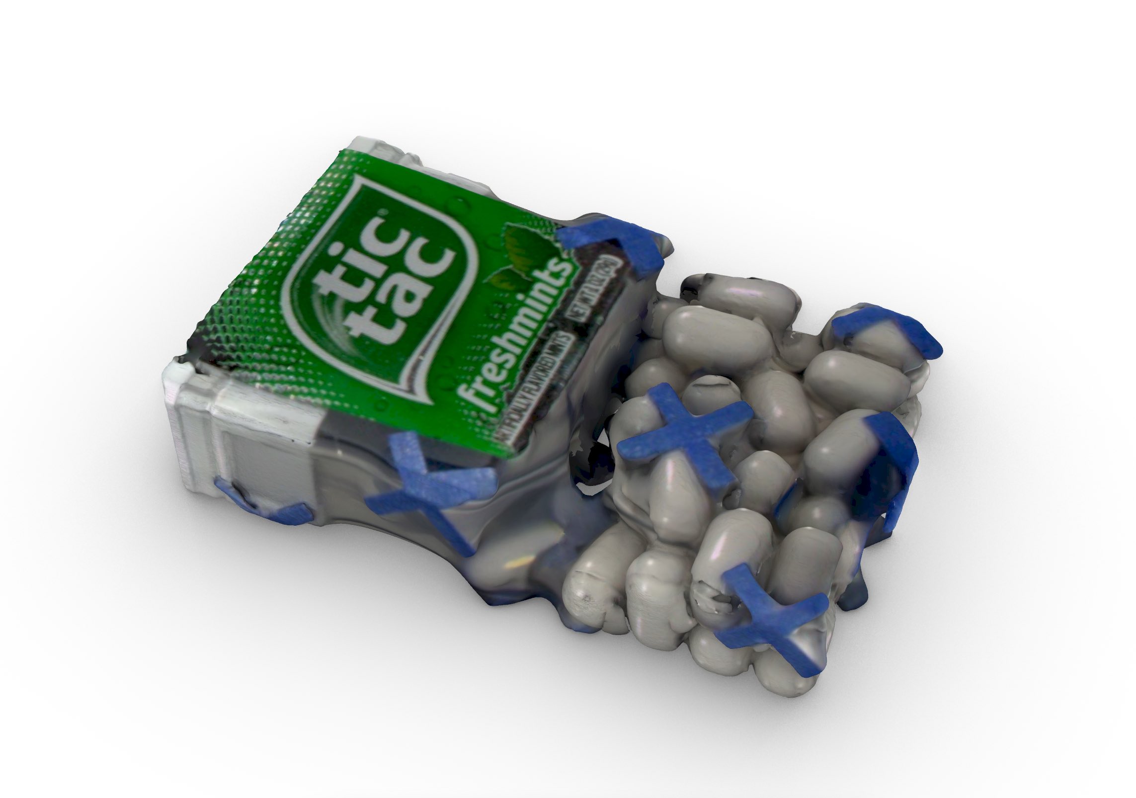
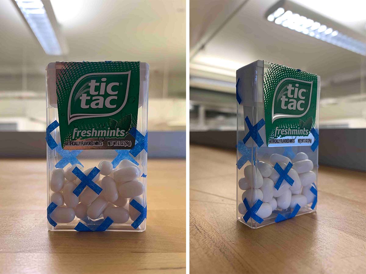
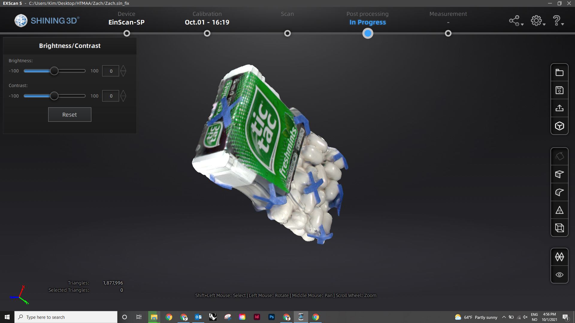
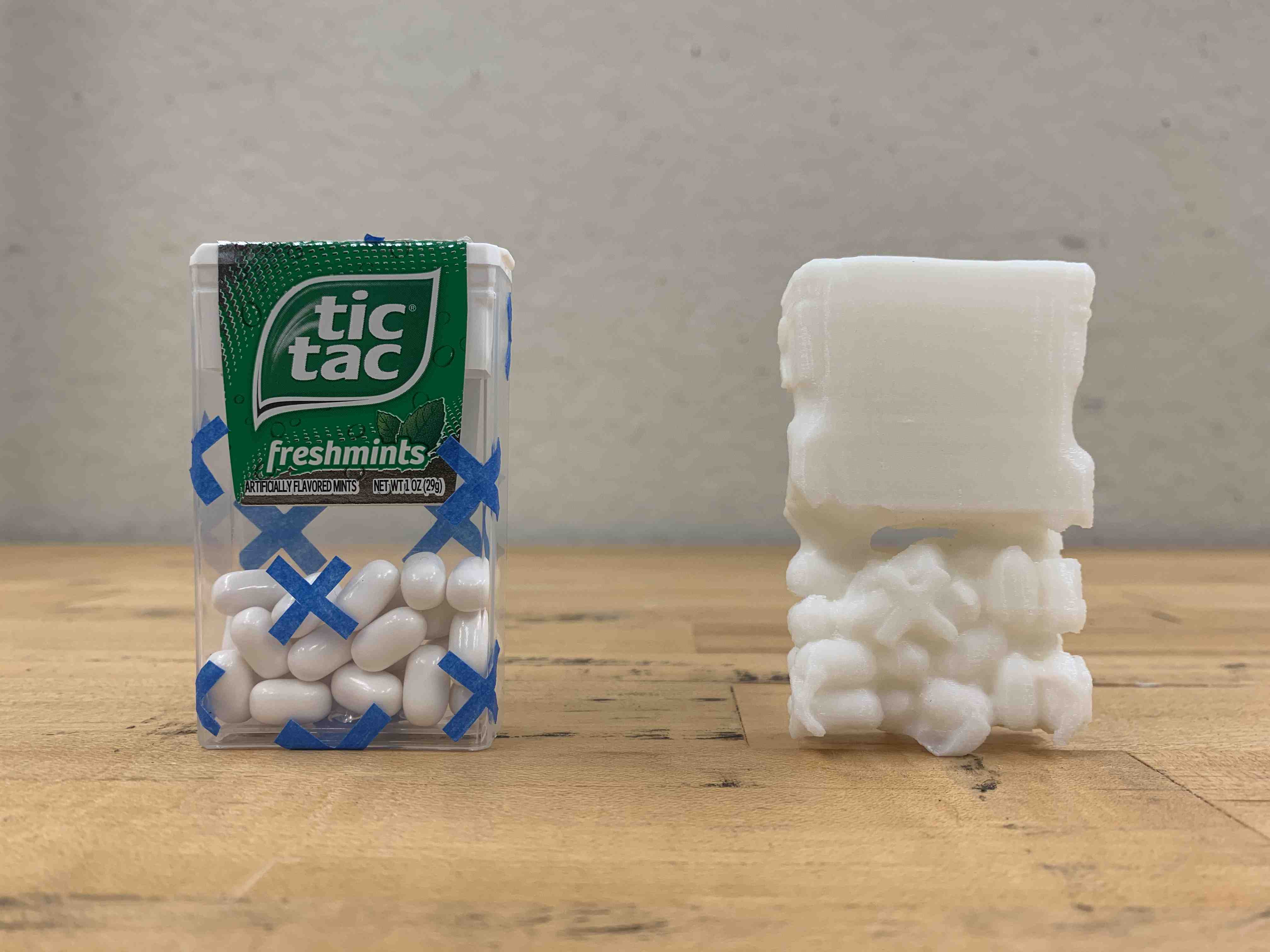
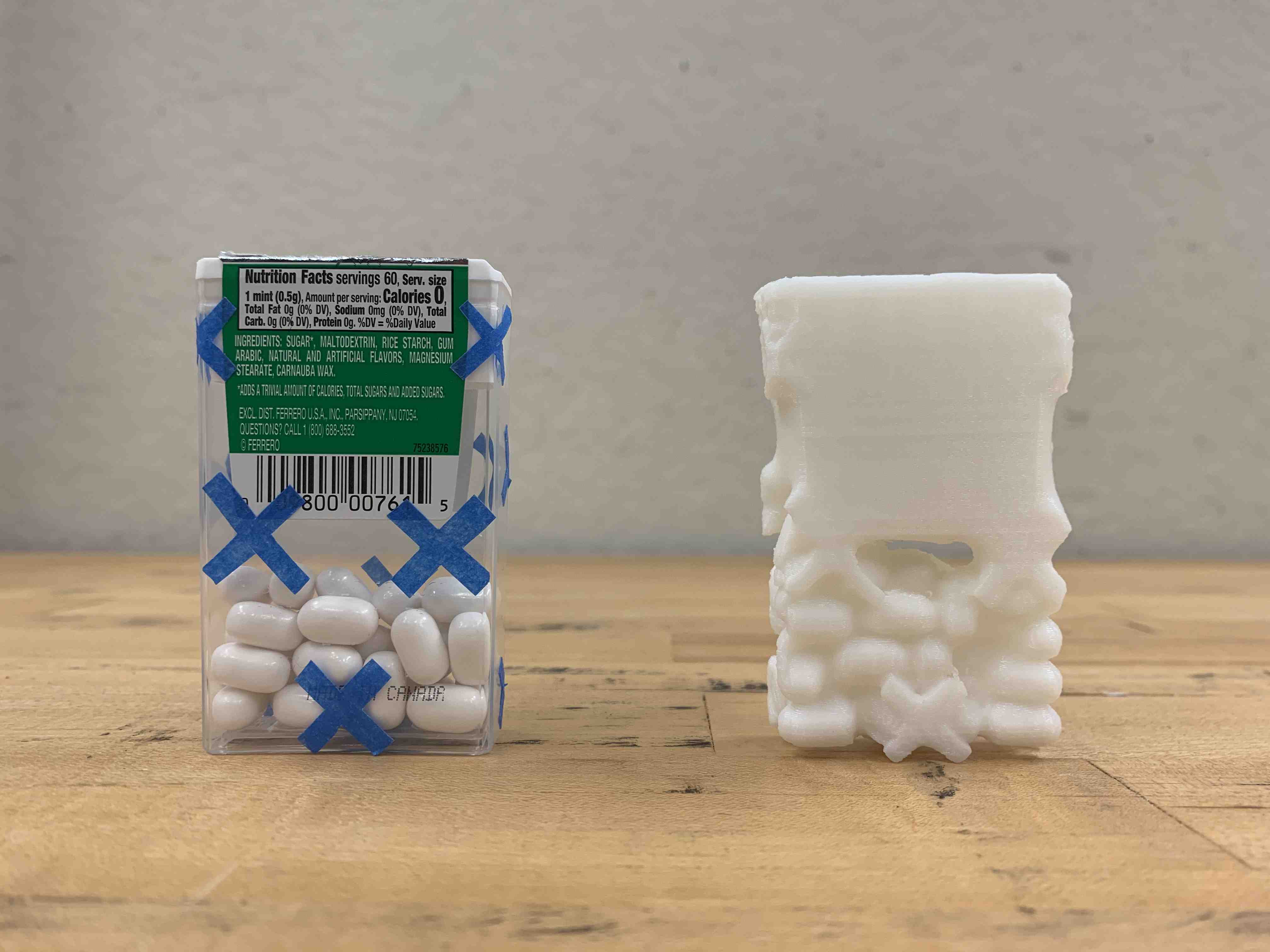
3D scanning often prefers multicolored, matte surfaces which provide registration marks across the body of the object. For this reason, I chose an object that would challenge some of the scanner's glitches. The tictac dispenser has it all: transparent sufaces, reflective graphics, and matte elements with shadows and voids. To help register the boundry of the transparent container I applied a series of (painter's tape) stickers.
Pictured below is the a rendered view of the 3D scanned tictac dispenser with the painter's tape registration marks.
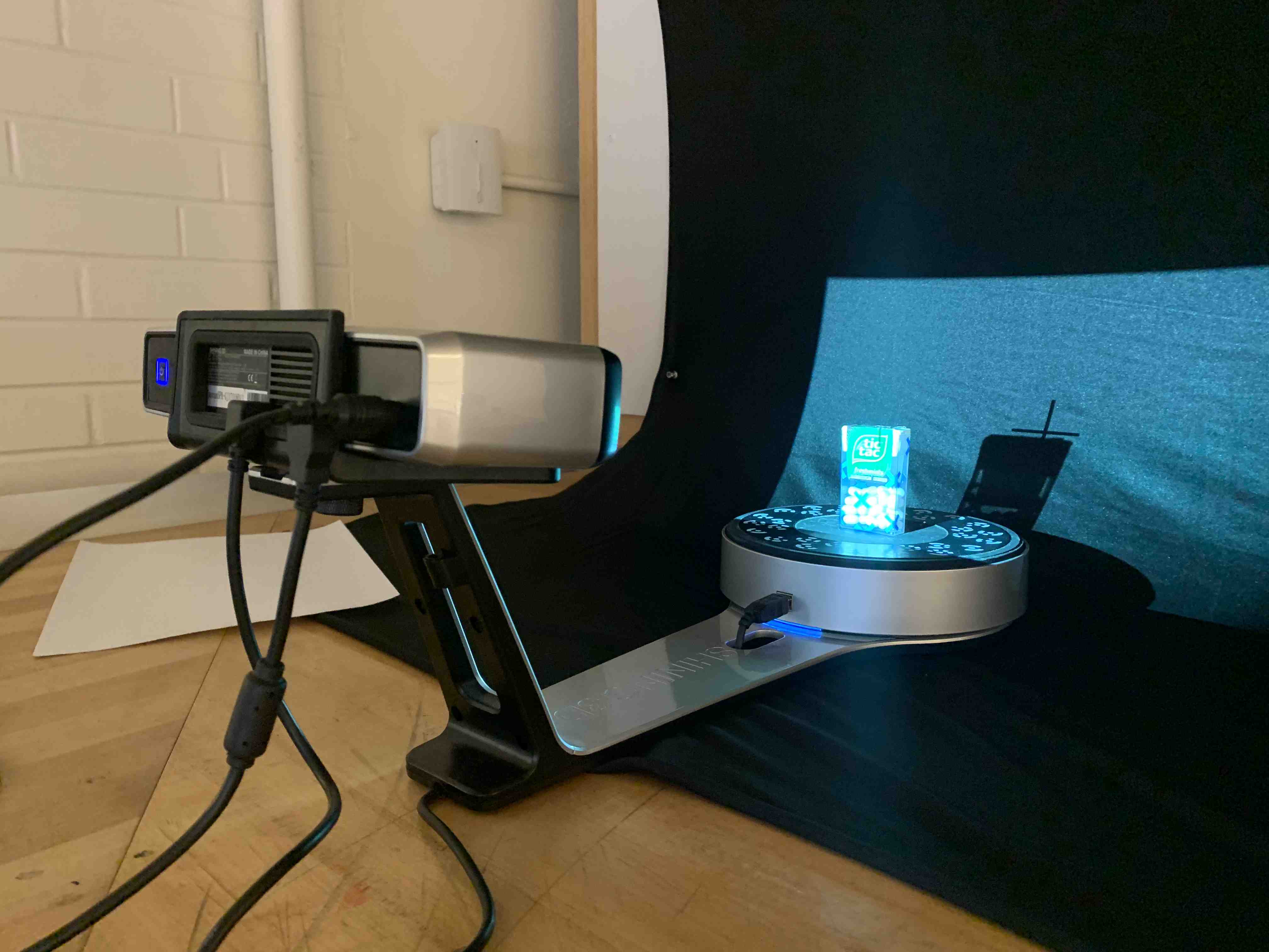
To start this assignment, my group and I used our classmates, Kim's 3D scanner, EinScan-SP, which he rented from MIT. The EinScan-SP is a structured light desktop scanner with 0.05mm accuracy and an attached turntable. To begin, the machine needs to be calibrated with a resolution target which is placed on the turntable.
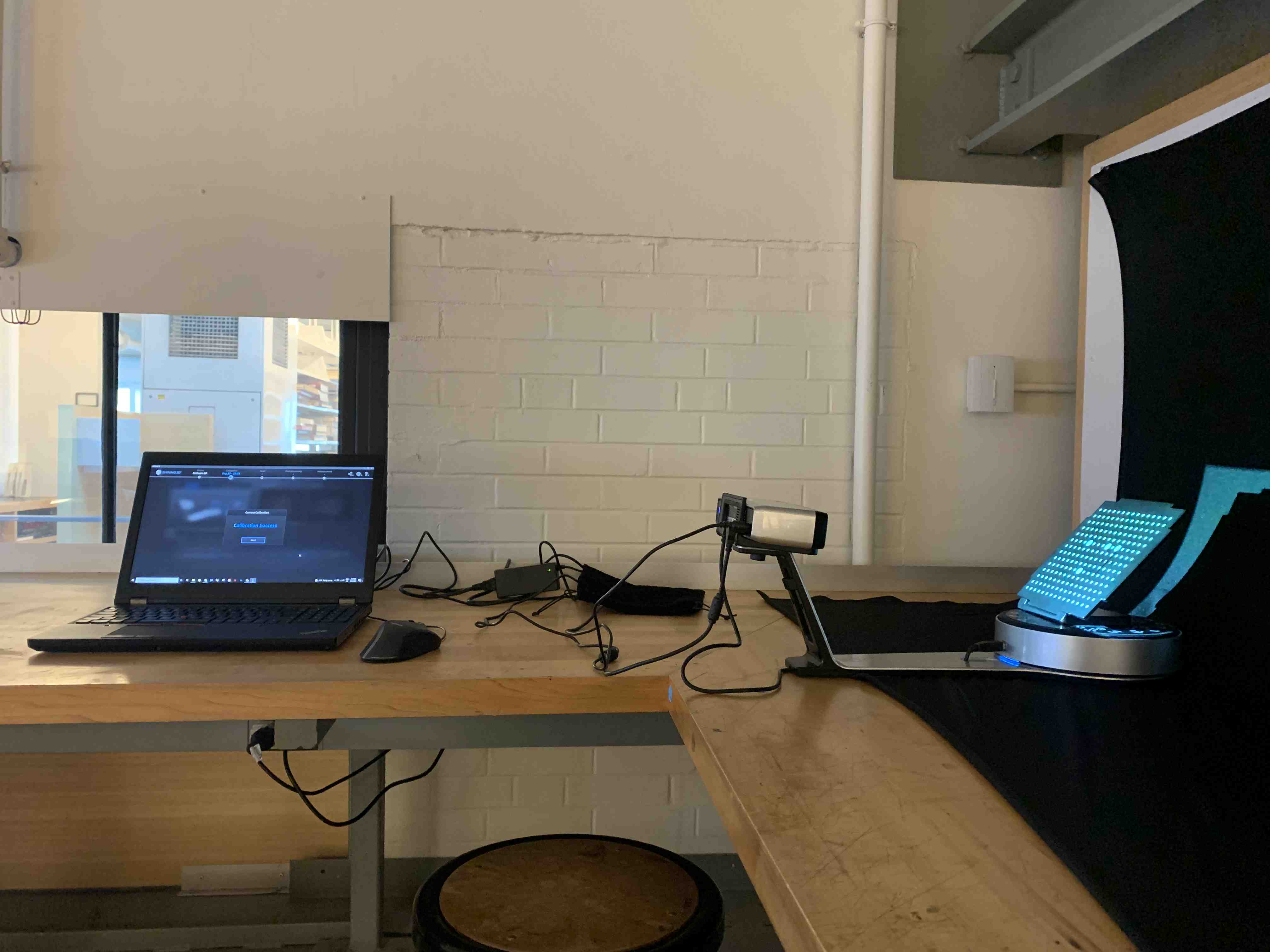
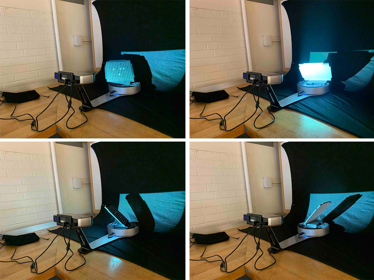
Then, once calibrated you place the small object in the center of the turntable so that the calibration stickers on the bed of the machine remain visible. You can use this scanner without the turntable, and place it on a tripod, if you need to scan larger objects.
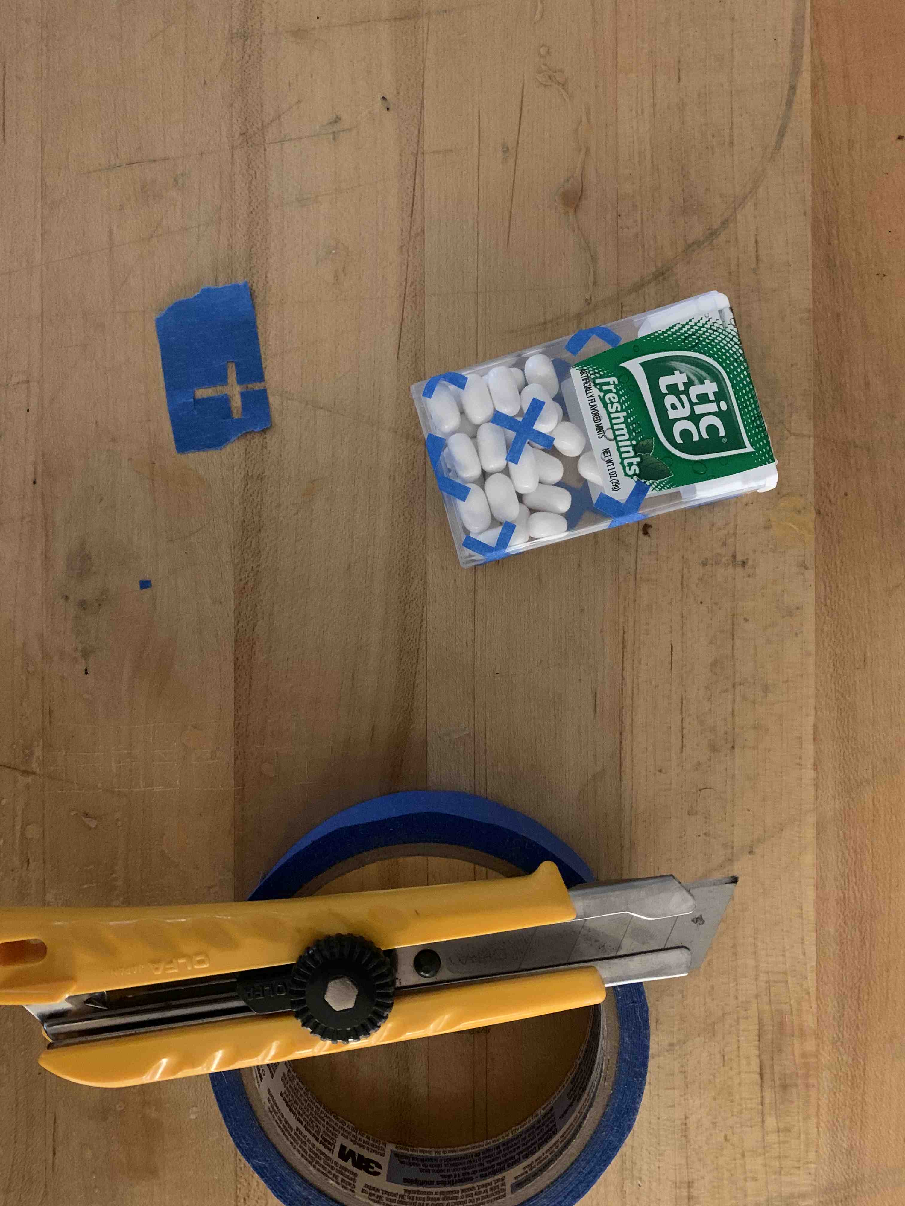
Before I placed the tictacs on the scanning bed, I cut a few +'s out of painter's tape, to act as registration marks in anticipation of the scanner being unable to capture the transparent boundary.
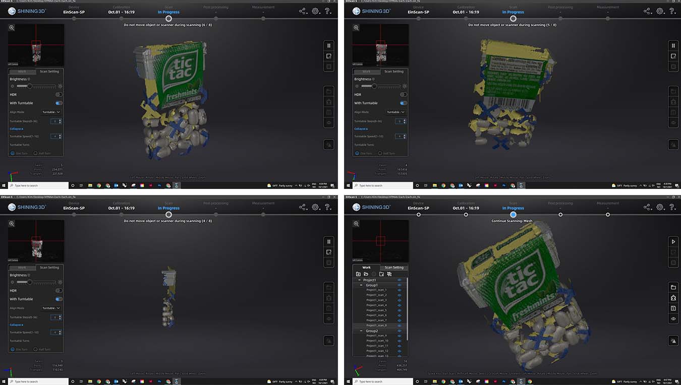
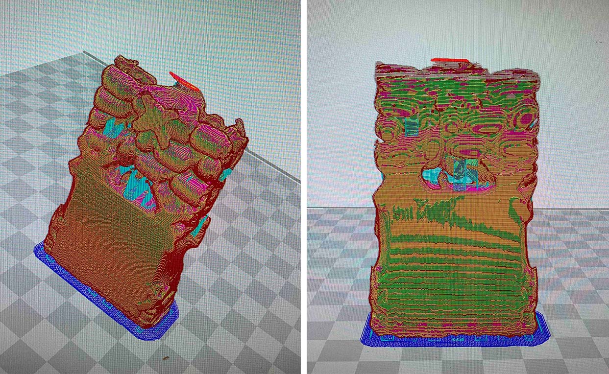
Once the scan is complete, the Shining 3D software can collapse several scans together (pictured below are two scans of the tictacs, one upright and one on its side), and make a watertight mesh and texture map of the object.

Part 2, characterizing the 3D printer:
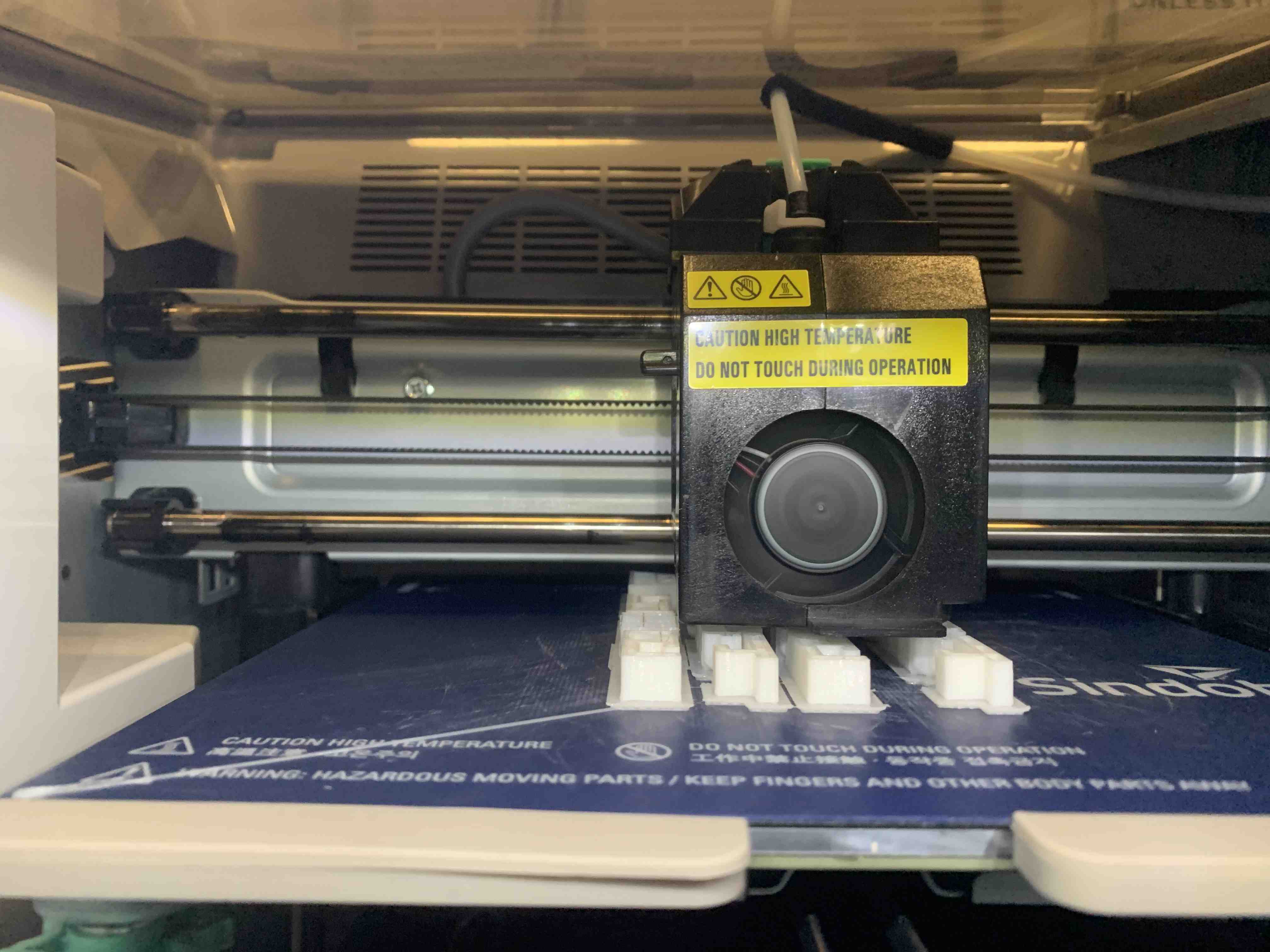
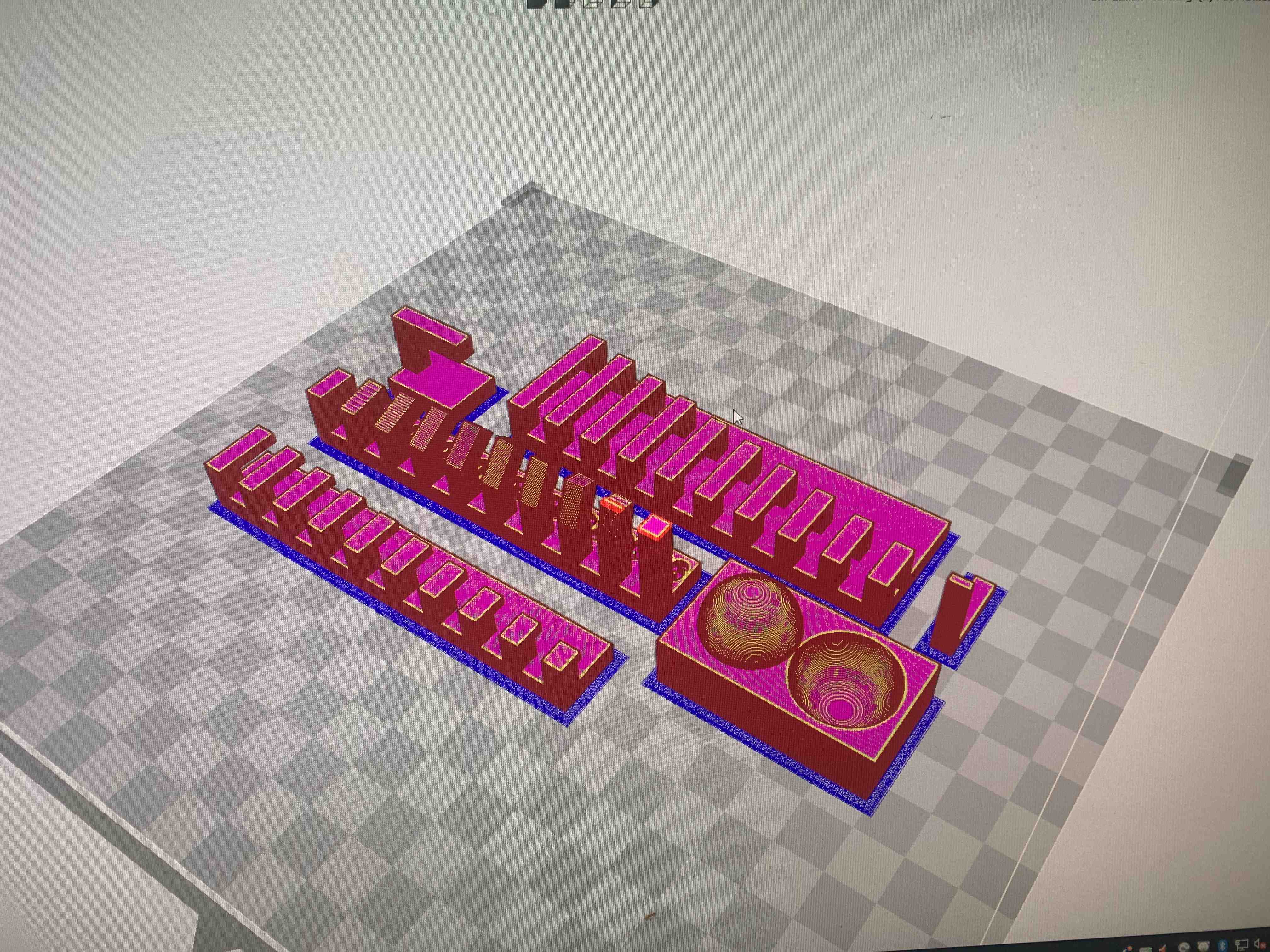
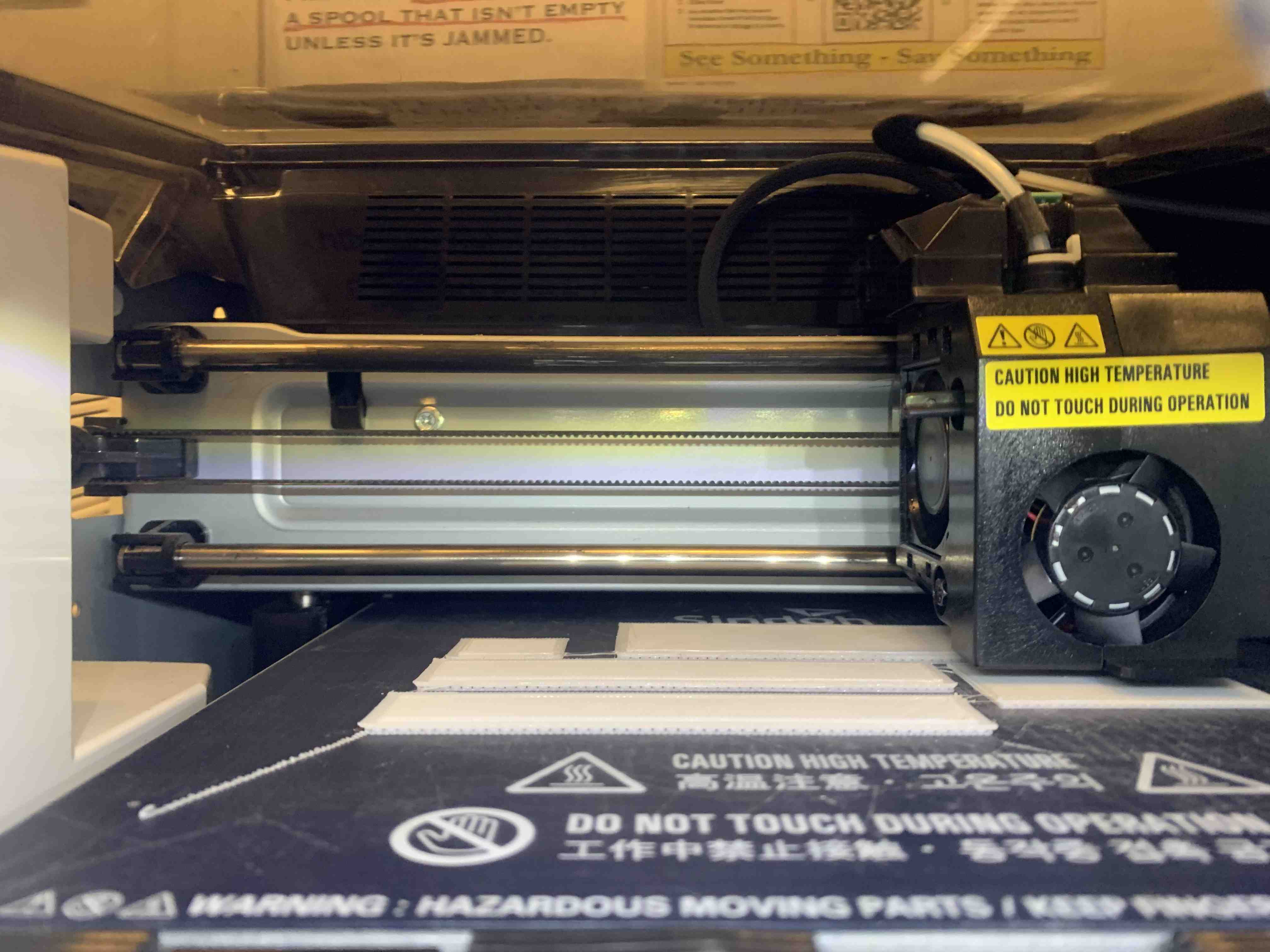
To start this part of this week's assignment, my group and I downloaded the provided stl's to characterize the 3D printer. To print our parts for this assignment we used the architecture department's Sindoh, 3DWOX and 3DWOX-01 printers. These are the most common printers in the department and offer 24/7 access.
When characterizing these machines we arranged the provided files on the print bed to run one complete job with the same settings. PLA filament with the print nozzle at ~200 deg F. Because the department has two different machines, the .gcode needs to be saved according to the machine you are using. For the older Sindoh, 3DWOX the .gcode needs to be saved as DP200, whereas, the newer 3DWOX-01 should be exported as 3DWOX-01.
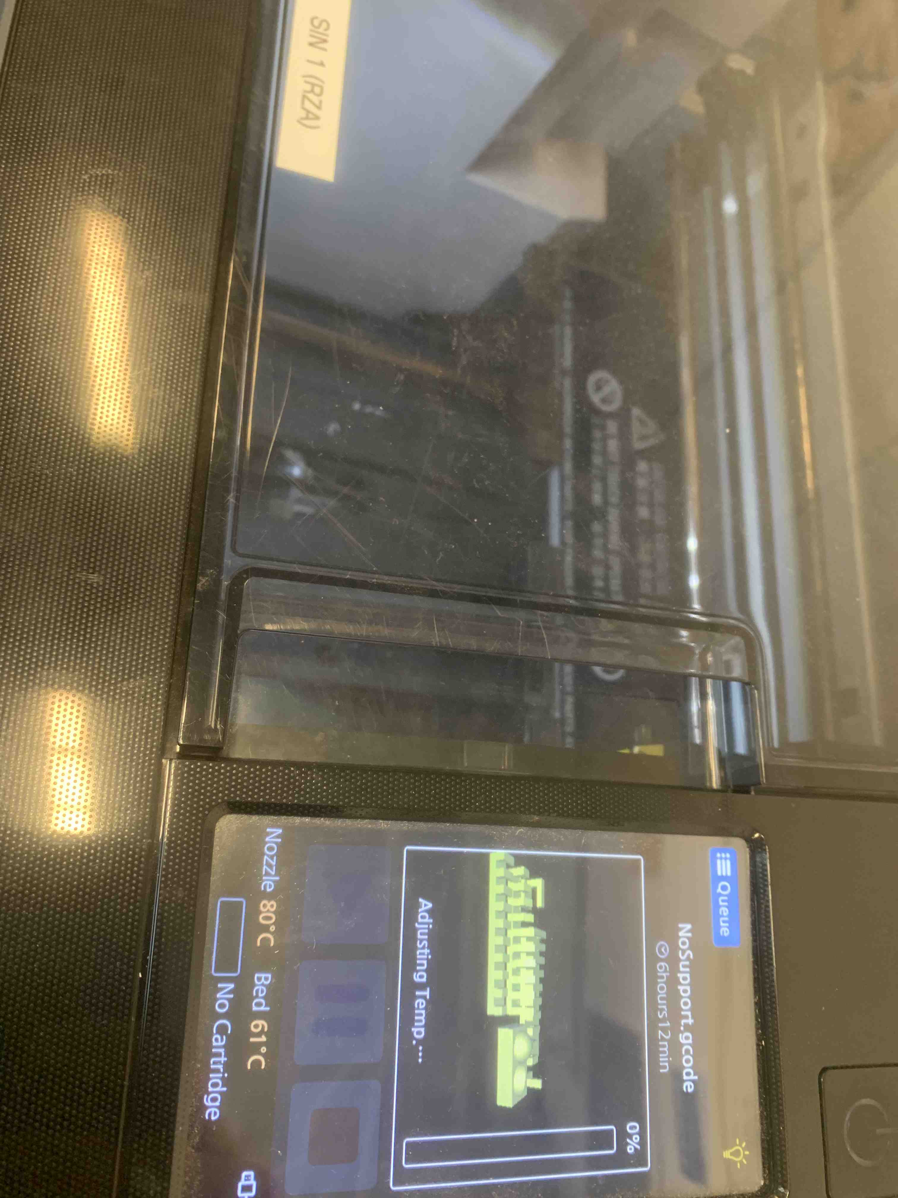
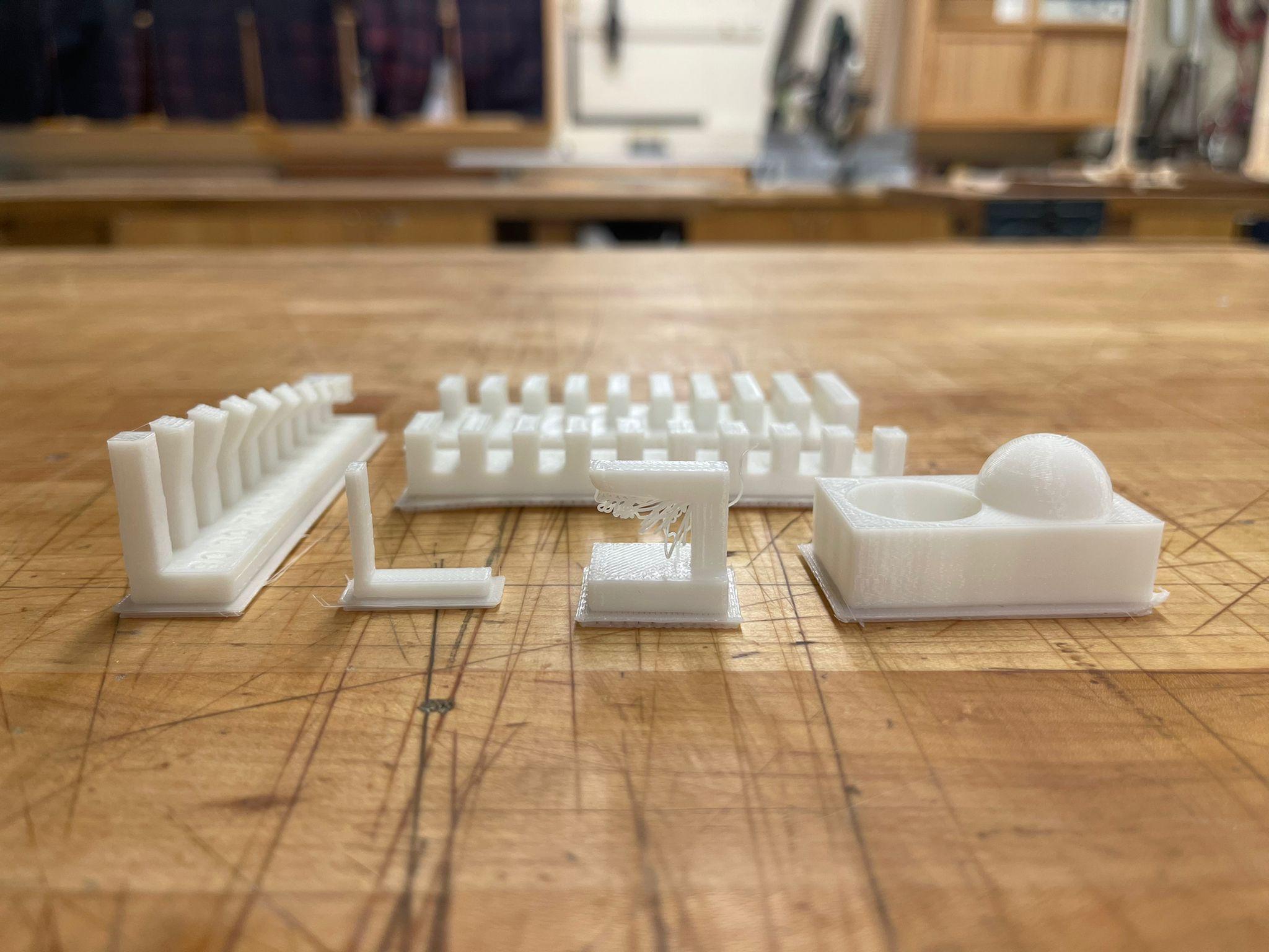
We watched the 3D printer for 10 minutes or so to be sure that the first layer adhered properly, and then checked back roughly every hour.

The result was very similar to the examples provided during class, the PLA filament began to sag at angles over 30deg-ish.
Part 3, 3D printing:
For this week's 3D printing assigment I printed both the tictac scan and a test connection for my final project. Pictured below is the PLA tictac.
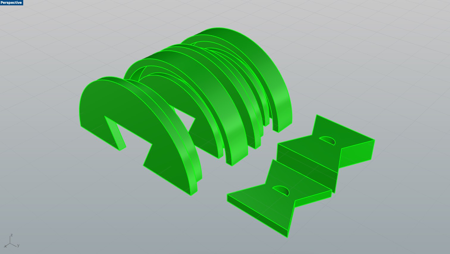
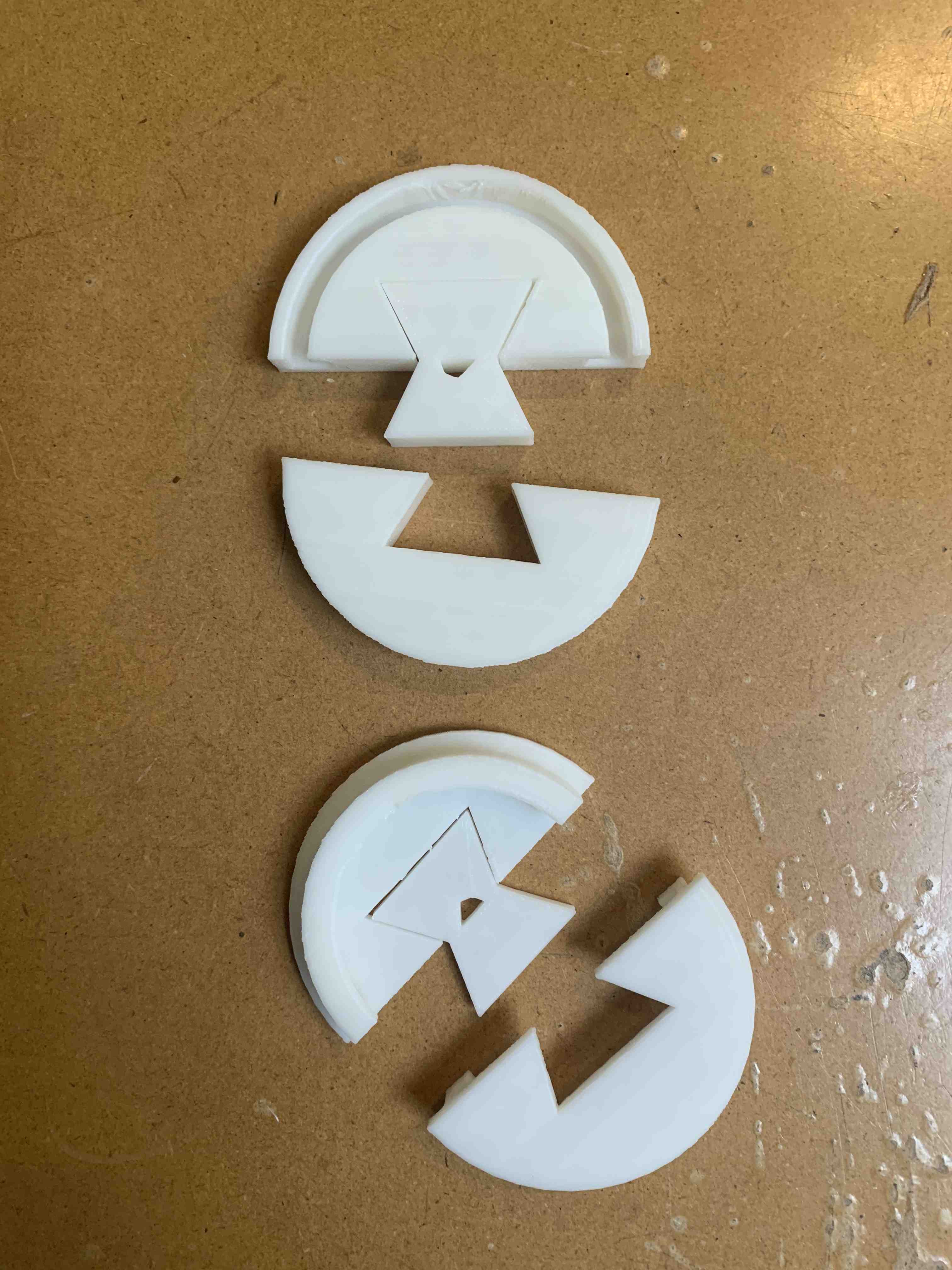
And secondly, pictured below are two discs that slot together and rotate on a central point. I am using these discs as a test for my final project. The difficulty with this test, was calibrating the tolerance between the discs and the interlocking joints. What I learned was that the dry fit between a butterfly joint needs to be tighter than anticipated.