
Week 6
Computer-Controlled Machining
Week Highlights
This week focuses on computer-controlled machining, covering CAM workflows, CNC milling techniques, and creating large-scale projects. We explore subtractive manufacturing processes and learn to make something big (~meter-scale).
Group Assignment
CNC router characterization: runout and clearance measurements
Design Completed!
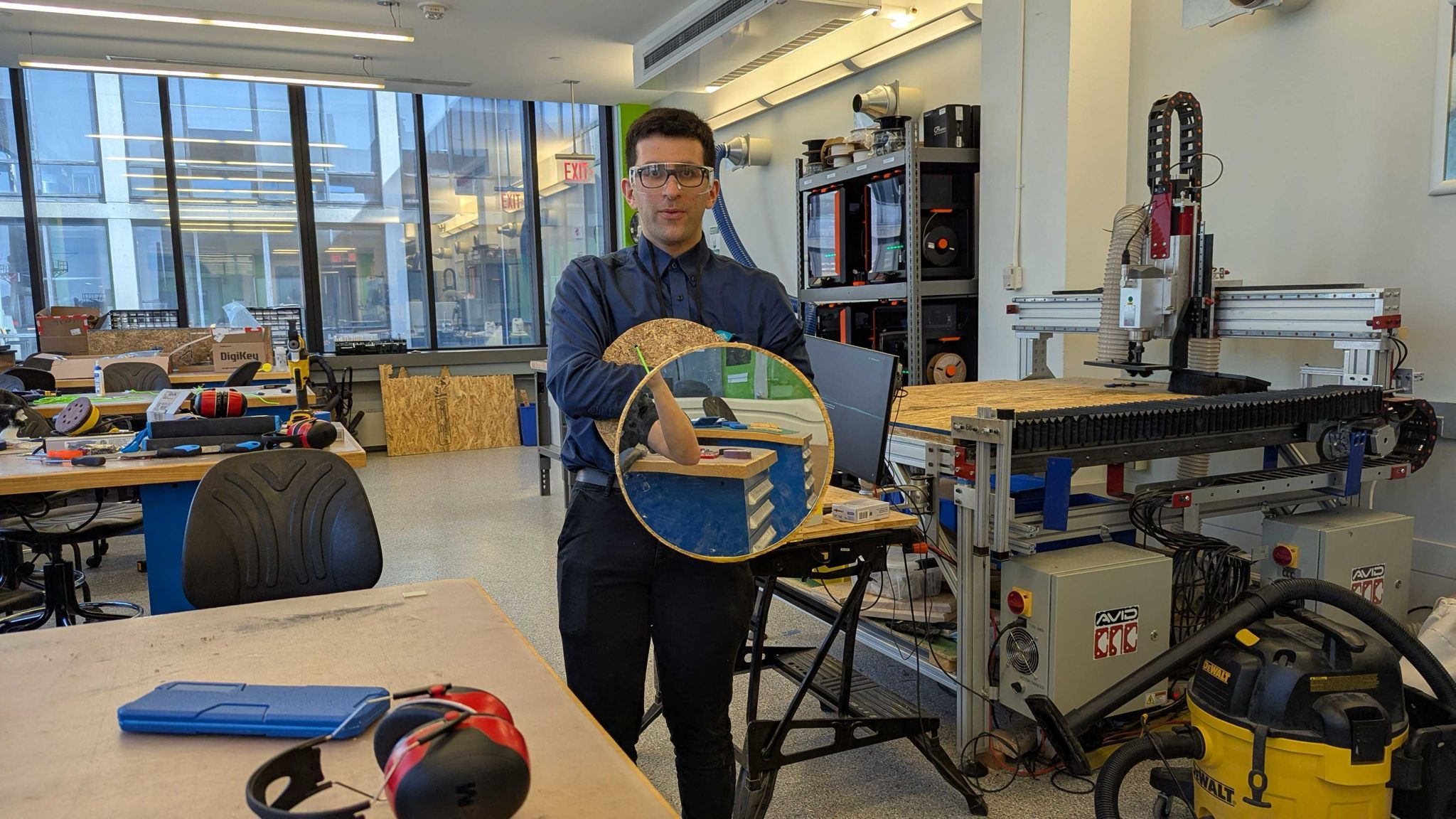
Floating mirror tensegrity design process
Assembled Results
3D printed and wood floating mirrors
3D Printed Horizontally Stable
3D printed assemblies demonstrating horizontal stability
Wood Horizontally Stable
Wood assembly showing horizontal stability progression
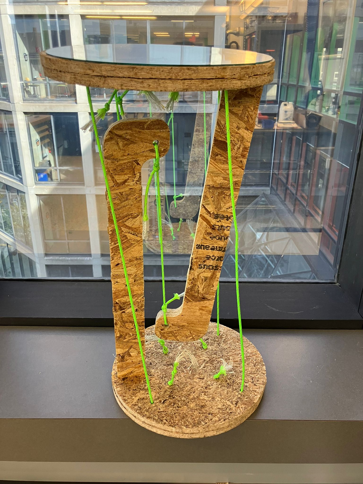
Floating Mirror
Final floating mirror configuration
Table of Contents
Course Content
Machining & CAM
Assignments & Projects
Computer-Controlled Machining
This week covers computer-controlled machining processes, focusing on subtractive manufacturing techniques for creating large-scale projects. We explore CAM workflows, CNC milling operations, and learn to make something big (~meter-scale) using precision machining tools.
This Week's Goals
- Characterize CNC machining process
Test design rules, speeds, feeds, and toolpaths for CNC milling - Make something big
Design, mill, and assemble a meter-scale project using CNC machining - Master CAM workflows
Learn computer-aided manufacturing processes and toolpath generation
Assignments
- Group Assignment
Do your lab's safety training; test runout, alignment, fixturing, speeds, feeds, materials, and toolpaths for your machine - Individual Assignment
Make (design+mill+assemble) something big (~meter-scale); extra credit for no fasteners/glue, curved surfaces, and three-axis toolpaths
Tools & Materials
- CNC Machines — ShopBot, Tormach, Haas, Shapeoko, Maslow
- Stock Materials — MDF, plywood, OSB, HDPE, aluminum
- Tooling — End mills, V-bits, drills, router bits
- CAM Software — Fusion 360, VCarve Pro, Mastercam
Recitation Notes: How to Make (Almost) Anything Big!
Comprehensive technical overview of subtractive manufacturing processes, CAM workflows, and design strategies for large-scale fabrication.
MIT CBA Academy Technical Documentation
Expert instruction from MIT CBA Academy covering subtractive processes, safety protocols, manufacturing workflows, and advanced machining techniques.
Reference Documentation
Live Discussion:
Complete Documentation:
Part 1 — Alfonso: Subtractive Manufacturing Fundamentals
Comprehensive overview of subtractive manufacturing processes, from basic 2-axis operations to advanced 5-axis machining capabilities.
Axis Control Configurations
Basic Operations
- 2-Axis: Water jetting, laser cutting — surface path operations
- 2.5-Axis: Primary focus — controlled depth cutting
Advanced Operations
- 3-Axis: Full XYZ coordination (limited by stock depth)
- 5-Axis: Advanced — tilt and cut normal to surface
Subtractive Manufacturing Advantages
Scale & Materials
- Larger scale projects
- New material capabilities
Precision & Quality
- Better tolerances
- Superior precision
Production & Capability
- Production capabilities
- Overcoming additive limitations
Critical Safety Protocols
⚠️ Mandatory Safety Requirements
- Spindle Range: 7k-15k RPM operation
- Continuous Monitoring: Listen, smell, observe
- Never Alone: Always supervised operation
- Personal Safety: Secure hair, sleeves, no jewelry
- Focus Required: No distractions during operation
- Emergency Stop: Know location and procedure
Tooling Selection & Applications
Primary Tools
- Flat End Mill: General purpose cutting operations
- Ball End Mill: Tool change speed optimization
Specialized Tools
- V-Bits: Detailed work and engraving
- Drills: Precision hole making operations
Feeds and Speeds Optimization
Critical parameters for successful machining operations, tool life optimization, and surface quality control.
Computer-Aided Manufacturing Workflow
Fusion 360 manufacturing mode provides comprehensive CAM workflow for toolpath generation, simulation, and machine control.
Joint Design Solutions
Reference Resources:
Essential Tools:
NIFTY DOGBONE (60-day free trial)
Critical Fusion 360 add-in for joint design optimization
Part 2 — Dan: Advanced Manufacturing Techniques
Advanced manufacturing strategies covering design optimization, process control, and quality assurance for large-scale fabrication.
Design Optimization for Large-Scale Fabrication
Design Considerations
- Appropriate scale and proportions
- Material selection optimization
- Design for manufacturability
- Assembly and joining strategies
Setup & Configuration
- Workpiece fixturing and alignment
- Tool selection and installation
- Coordinate system establishment
- Safety checks and verification
Process Control & Optimization
Speeds & Feeds
- Spindle speed optimization
- Feed rate calculations
- Chip load considerations
- Tool life management
Geometry & Toolpaths
- 2D contour operations
- Pocket clearing strategies
- Roughing and finishing passes
- Toolpath optimization
Advanced Machining Strategies
Heights & Passes
- Clearance height planning
- Step-down strategies
- Multiple pass operations
- Depth control and safety
Linking & Finishing
- Toolpath linking strategies
- Lead-in and lead-out optimization
- Surface finish requirements
- Post-processing considerations
Simulation & Quality Assurance
Fusion 360 CAM Simulation Tools
Time Analysis:
- Simulate → Statistics → Estimated completion time
- Toolpath efficiency optimization
Quality Verification:
- Right-click stock → save as .STL for diagnosis
- Toolpath verification and collision detection
- Material removal simulation
Training
Essential training materials and procedures for computer-controlled machining and CAM workflows.
CAM Tutorial
Comprehensive CAM tutorial in Fusion 360 covering toolpath generation, machining strategies, and workflow optimization for CNC operations.
Anthony's comprehensive CAM tutorial in Fusion 360 covering toolpath generation and machining strategies
Helpful Documentation
Essential resources for computer-controlled machining and CAM workflows.
Lecture Information
-
Computer-Controlled Machining - MIT Academy
Comprehensive resource covering CNC machining principles, CAM workflows, toolpath generation, and machine operation. Includes tutorials on design for machining, fixturing, and safety procedures.
Recitation Information
-
Detailed documentation covering CAM workflows, toolpath strategies, machining parameters, and best practices for computer-controlled machining operations.
Group Assignment: EECS Shop CNC Router Characterization
Characterize the design rules for the EECS shop CNC router through systematic testing of runout, alignment, fixturing, speeds, feeds, materials, and toolpaths.
Characterization Parameters
Comprehensive testing of CNC router capabilities to establish design rules and manufacturing parameters for successful machining operations.
Reference Materials
Source: MIT HTMAA Slack Discussion
Detailed notes from Anthony's training session on CNC router characterization and design rules
Critical Parameters for Characterization
- Runout: Tool concentricity deviation affecting kerf width and dimensional accuracy
- Alignment: Workpiece positioning accuracy for final part dimensional control
- Fixturing: Workholding methods using plastic/steel nails for secure stock positioning
- Speeds & Feeds: Optimized parameters balancing tool life, material removal, and surface finish
- Materials: OSB only (other materials require approval and additional cost)
- Toolpath Generation: 3HP spindle (2.2kW) with strict safety protocols
Expert Guidelines from Anthony
Design & Joints
- OSB Joints: Slots and tabs optimal; other joints challenging due to material structure
- Component Strategy: Design joints in-place; create components from bodies for joint features
- Finishing: File/rasp for non-filletable edges; expect multiple days for sanding
Tooling & Safety
- Tool Selection: Two-tool strategy: small for detail, large for rough cuts
- Safety Protocol: No jewelry/loose items; secure tool mounting critical
- Preparation: Arrive with CAD complete and CAM attempted; post-process before machining
⚠️ Critical Safety Note
Tool Security: Fires can occur from excessive depth or steep angles. Previous incidents involved frame contact. Always verify tool tightness before operation.
Post-Processing Check: Verify TAB_FIT_CHECK, tool diameter, corner radius (cr), and minimum height (zmin) parameters.
EECS Shop CNC Router Design Rules
Succinct guidelines derived from our characterization to ensure predictable outcomes on the EECS shop CNC router.
Runout
Measured at the tool: joints loosen with usage; fresh cuts are tighter.
| Metric | Value (in) |
|---|---|
| Average runout | 0.0036 |
| Standard deviation | 0.0020 |
| Median (freshly machined) | 0.0020 |
Use average + 1σ (~0.0056 in) as a conservative clearance allowance for press fits that will be tested repeatedly.
Dial/runout measurement indicating consistent concentricity with slight loosening after fit tests.
Clearance
Press-fit clearance tests across increments; loosened joints increase effective clearance over time.
| Peg length [in] | Hole size [in] | Clearance [in] | Joint type | Fit type |
|---|---|---|---|---|
| 1.995 | 2 | -0.005 | Interference | Press |
| 2 | 2 | 0 | Line-to-line | Transition |
| 2.005 | 2 | 0.005 | Clearance | Slip |
Use 0.005 in clearance for slip fits; interference fits require press assembly.
Clearance measurement setup showing press-fit testing across different peg sizes and hole clearances.
Full Runout Measurements
| Measurement | Value [in] | Notes |
|---|---|---|
| Fresh cut 1 | 0.002 | Initial measurement |
| Fresh cut 2 | 0.002 | Consistent |
| After fit test 1 | 0.004 | Joint loosening |
| After fit test 2 | 0.005 | Increased wear |
| After fit test 3 | 0.006 | Maximum observed |
Full Clearance Measurements
| Test | Peg [in] | Hole [in] | Result |
|---|---|---|---|
| Tight fit | 1.995 | 2.000 | Press required |
| Nominal | 2.000 | 2.000 | Snug fit |
| Loose fit | 2.005 | 2.000 | Slip fit |
Alignment
- Square stock to the bed; use probe to set origin at stock bottom-left.
- Match this origin in Fusion CAM manufacturing setup.
Fixturing
- Use plastic nails via plastic nail gun; place outside final contours where possible.
- Removal: crowbar to pop parts; slide to shear remaining nails; clean all nails from bed.
Speeds & Feeds
- Spindle: 10,000 RPM; Feed: 90–100 in/min; other values per Fusion defaults.
- Reference video: Anthony's CAM tutorial.
Materials
- OSB only. Other materials require prior approval and incur additional cost.
Toolpath Generation (Fusion CAM)
- Create a manufacturing model; convert bodies to components.
- Sketch stock size; use Arrange to nest components within the stock.
- Create a manufacturing setup aligned to stock bottom-left origin.
- Define parameters for each tool. Use two 2D contour toolpaths:
- 3/8 in (0.375) tool for primary contours.
- 1/4 in (0.25) tool for detail features.
- Simulate, post-process, and export for the router as required.
Systematic Test Part Design
Designed test part featuring 2-inch slots with 0.005" incremental clearances to systematically evaluate joint tolerances and press-fit characteristics.
Press Fit Clearance Matrix
-0.005"
Tight Fit
0.000"
Nominal
+0.005"
Loose Fit
Manufacturing Process Documentation
Systematic documentation of the CNC router characterization process from design to measurement, capturing key parameters for design rule establishment.
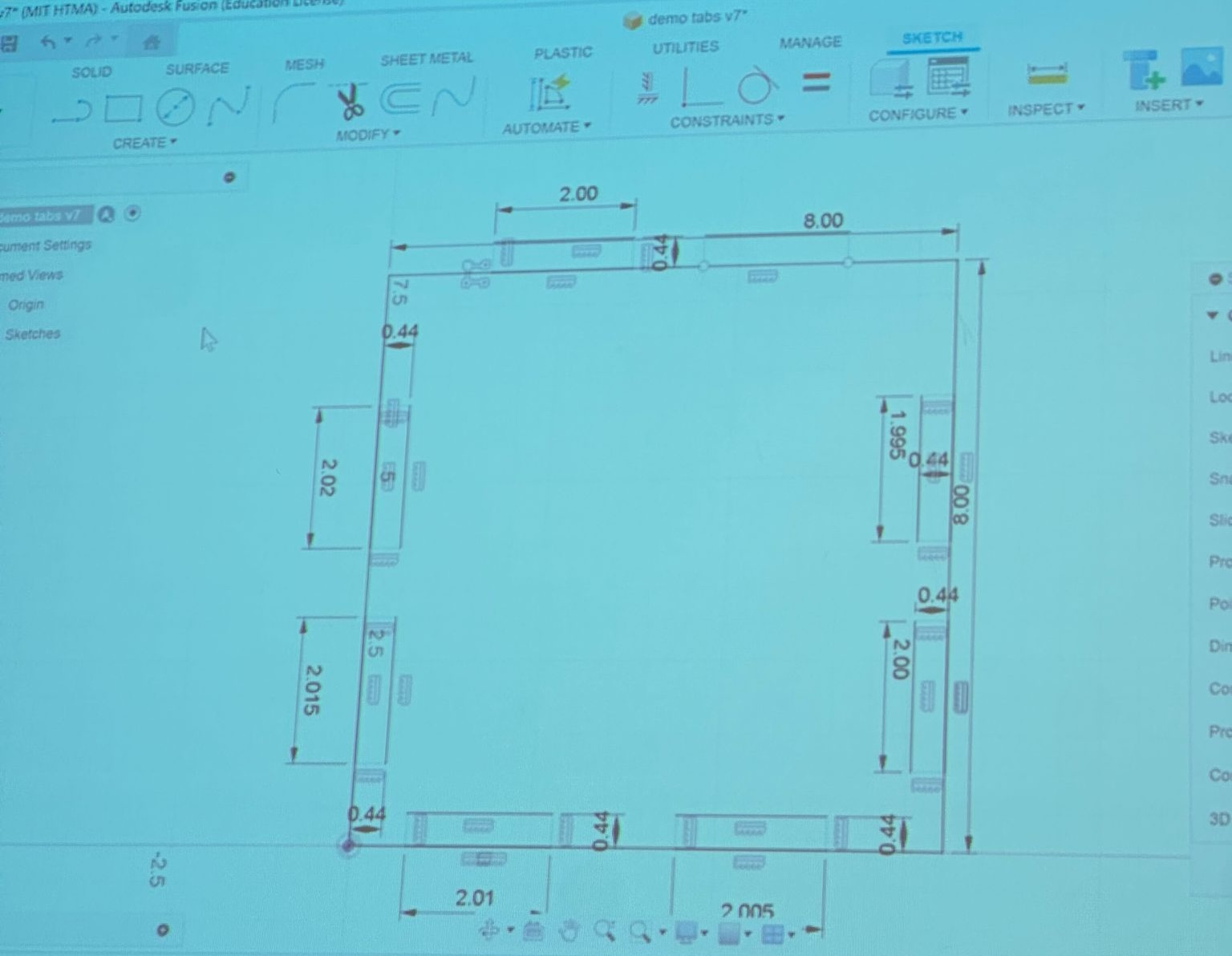
Demo tabs design featuring 2-inch slots with 0.005" clearance increments for systematic joint tolerance testing
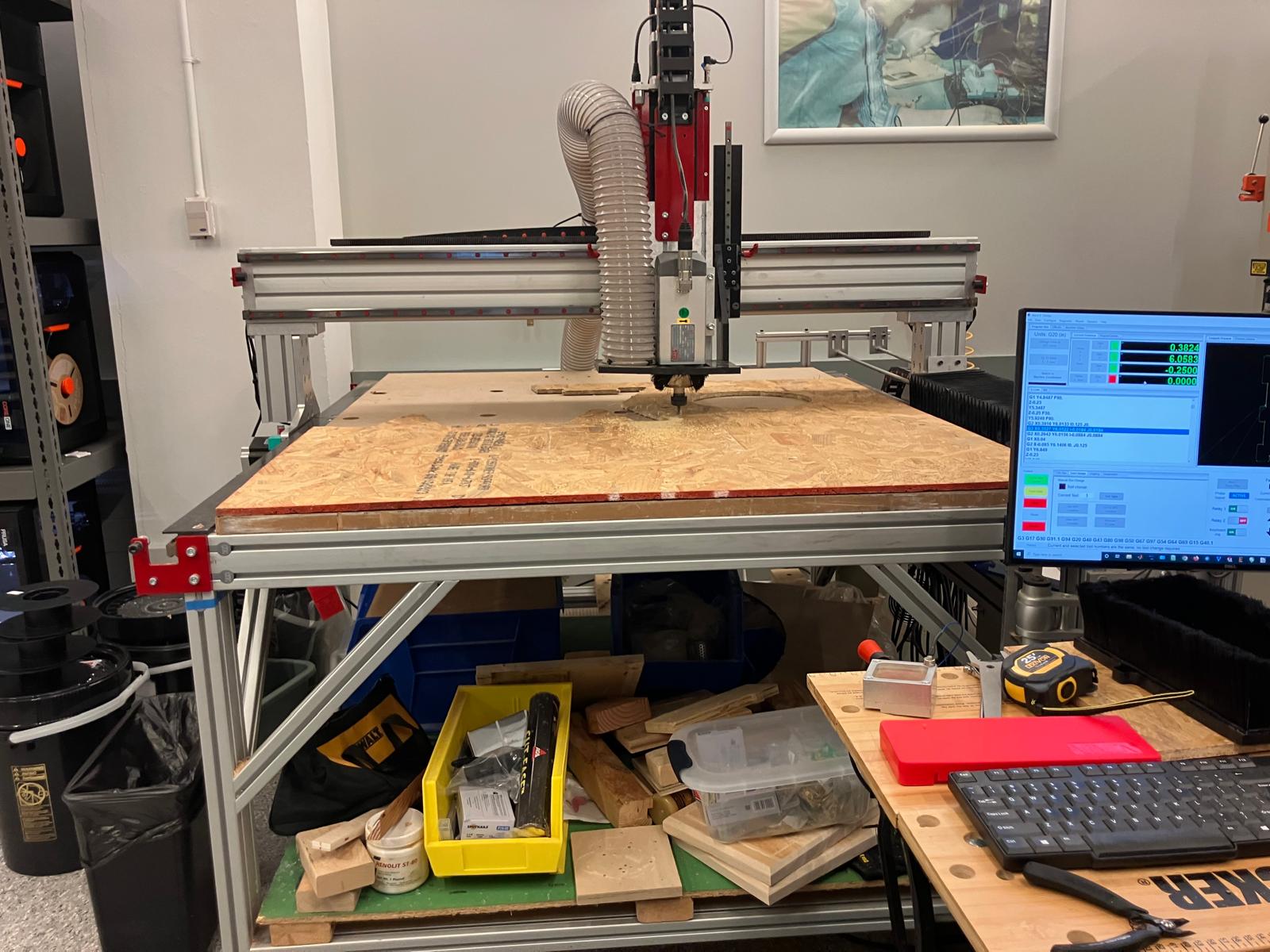
CNC router executing characterization cuts with 3HP spindle at optimized speeds and feeds for OSB material
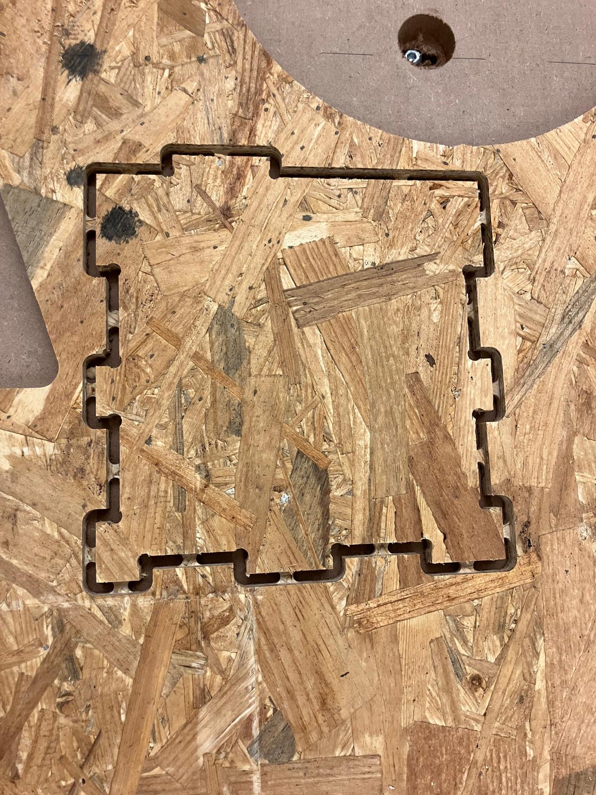
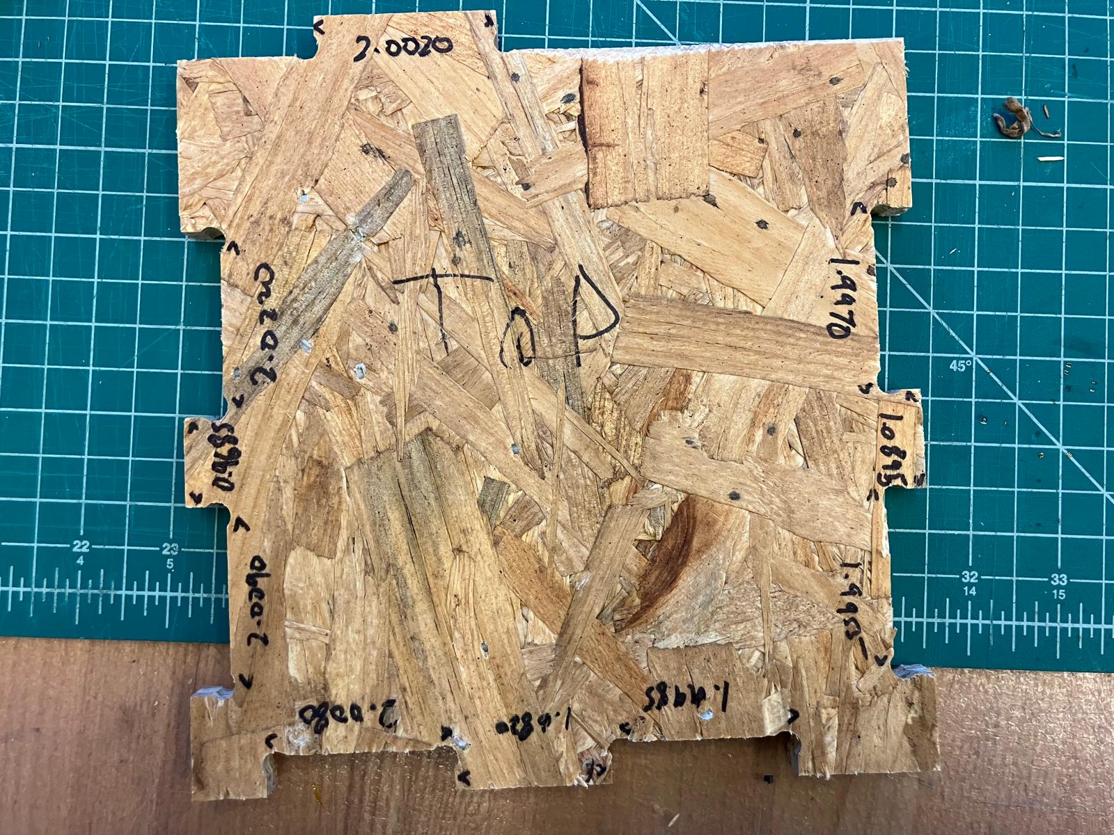
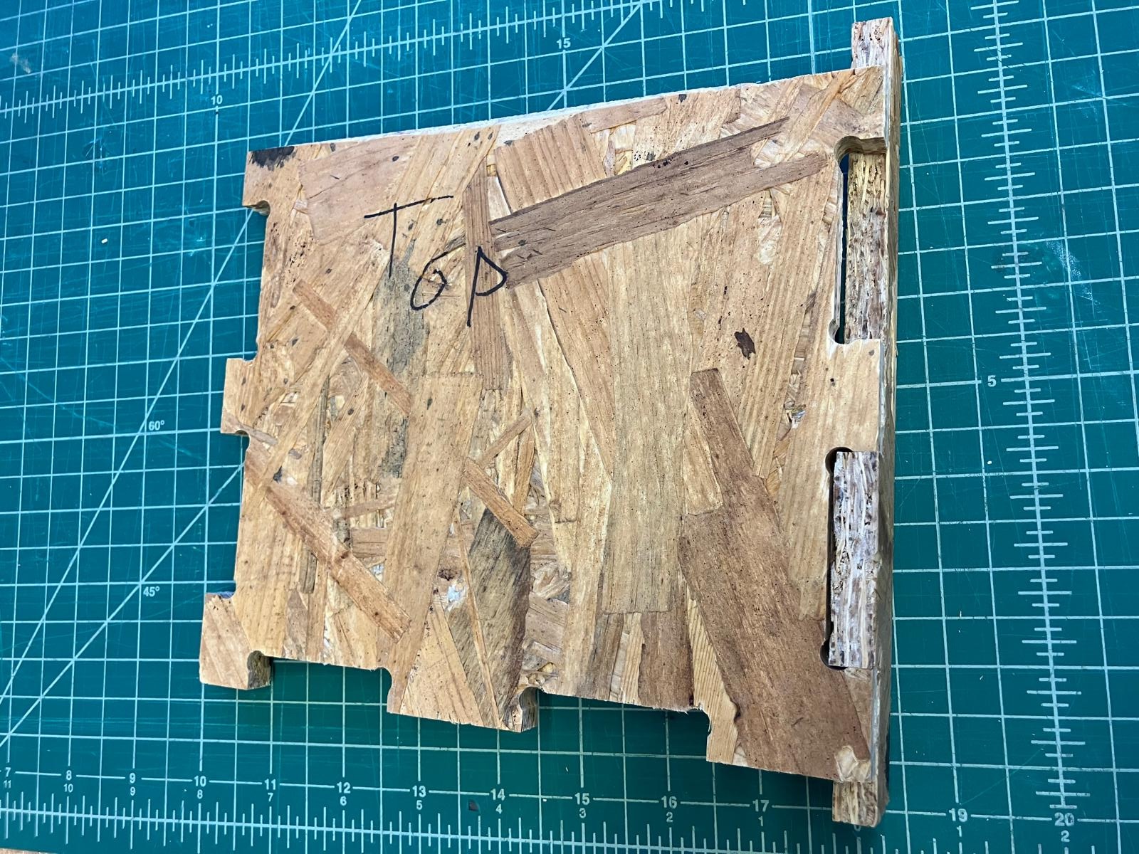
Completed test part showing three joint clearance variations (1.995", 2.000", 2.005") for press-fit tolerance analysis
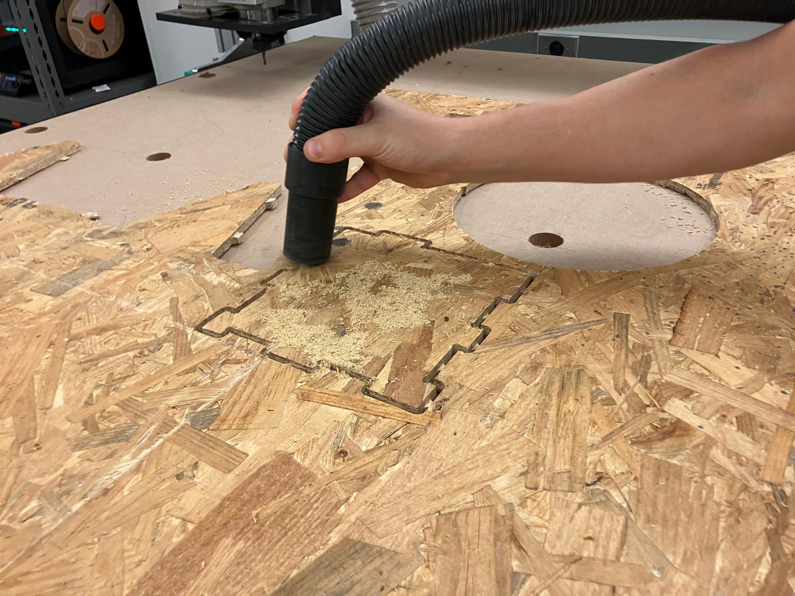
Post-machining cleanup using vacuum system to remove OSB dust and debris from work area and test parts
Bandsaw cutting for part separation and precision measurement using calipers to determine actual joint clearances and runout characteristics
Design Files
Demo Tabs v8.f3d: Complete Fusion 360 design file for CNC router characterization test parts with various joint clearances and tab configurations.
Characterization Completion Checklist
Priority Action: Measure runout using calipers based on test part design, then systematically complete all characterization parameters.
Measurement & Analysis
- ✓ Measure runout with calipers
- ✓ Complete alignment testing
- ✓ Document dimensional accuracy
Process Validation
- ✓ Verify fixturing methods
- ✓ Document speeds and feeds
- ✓ Validate toolpath generation
Individual Assignment: Floating Mirror
Design and fabricate a floating mirror using tensegrity principles, exploring both 3D printing and CNC machining approaches for large-scale fabrication.
0. Design Inspiration
Research and inspiration from various tensegrity table designs and floating mirror concepts to inform the project approach.
Tensegrity Resources
- How to Make Floating Tensegrity Table — Comprehensive guide with step-by-step instructions
- Tensegrity Table Build Video — Visual demonstration of construction process
- Advanced Tensegrity Techniques — Advanced construction methods and tips
- Tensegrity Physics Explanation — Understanding the underlying physics principles
- Basic Tensegrity Table — Fundamental tensegrity table design
- 3D Printed Tensegrity Model — Small-scale 3D printed tensegrity structures
- Tensegrity Table with Swappable Top — Modular tensegrity design with interchangeable surfaces
- Impossible Table Reddit Post — Community discussion and build examples
- Tensegrity Mirror Concept — Specific tensegrity mirror implementation
- MIT Fab Academy Tensegrity Project — Previous MIT student tensegrity work
- Tensegrity Construction Tips — Practical construction advice and techniques
- Tensegrity Table Assembly — Detailed assembly process demonstration
- DIY 3D Printed Tensegrity Tables — Complete DIY guide for 3D printed tensegrity
- MIT HTMAA Week 6 Project — Previous MIT HTMAA student CNC machining project
Hook Alternatives
- Hook Design Video — Hook design and implementation techniques
- 3D Printable Hooks — Various hook designs for 3D printing
- Pattern Holes in Fusion 360 — Creating patterned holes for hardware integration
Note: We decided to go without hooks or screw hooks if needed, focusing on clean design integration.
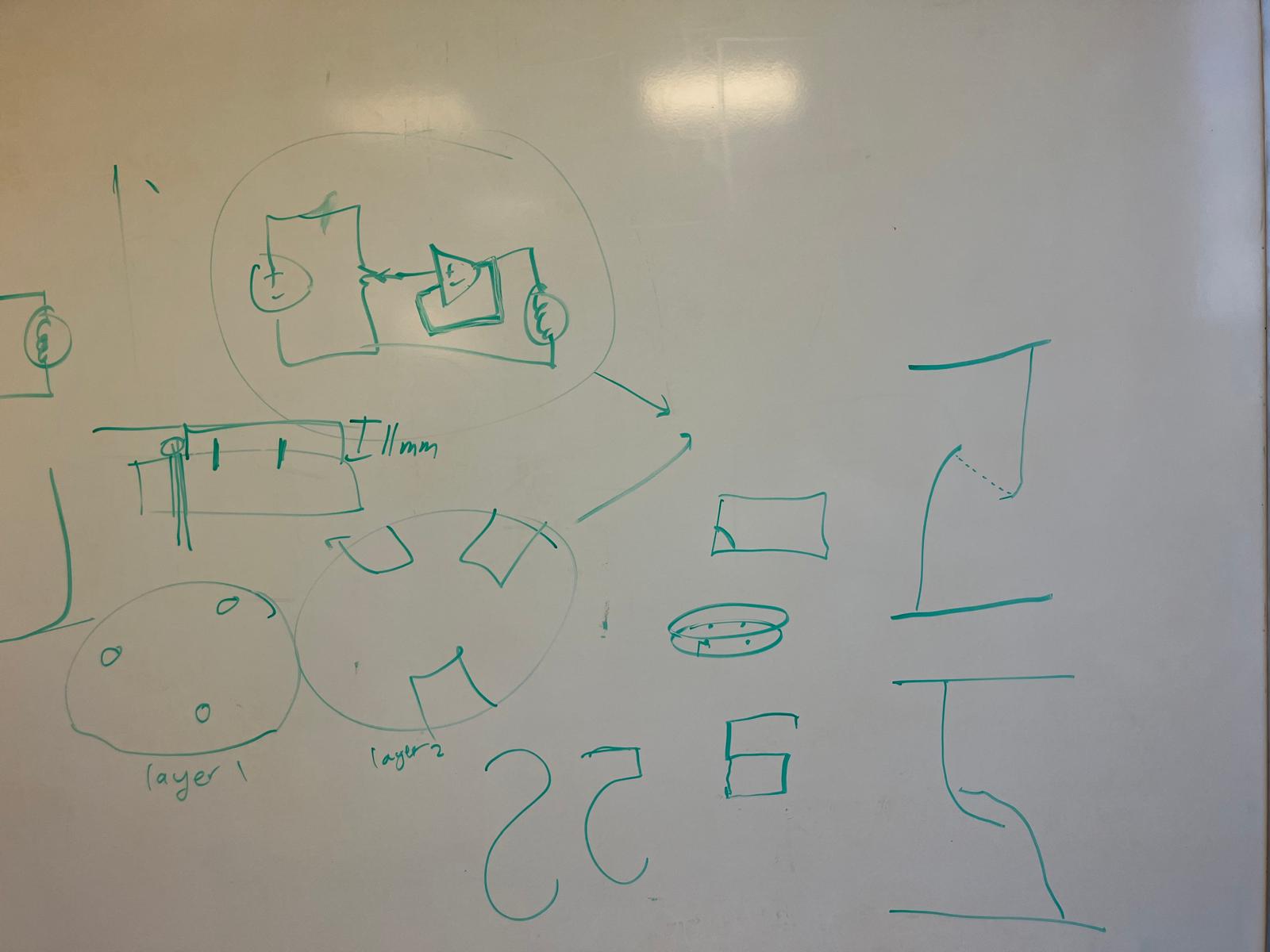
Design board discussions with Anthony during the floating mirror design process, exploring tensegrity principles and manufacturing considerations
1. Computer-Aided Design (CAD)
Design process for the floating mirror using Fusion 360, incorporating tensegrity principles and ensuring manufacturability for both 3D printing and CNC machining.
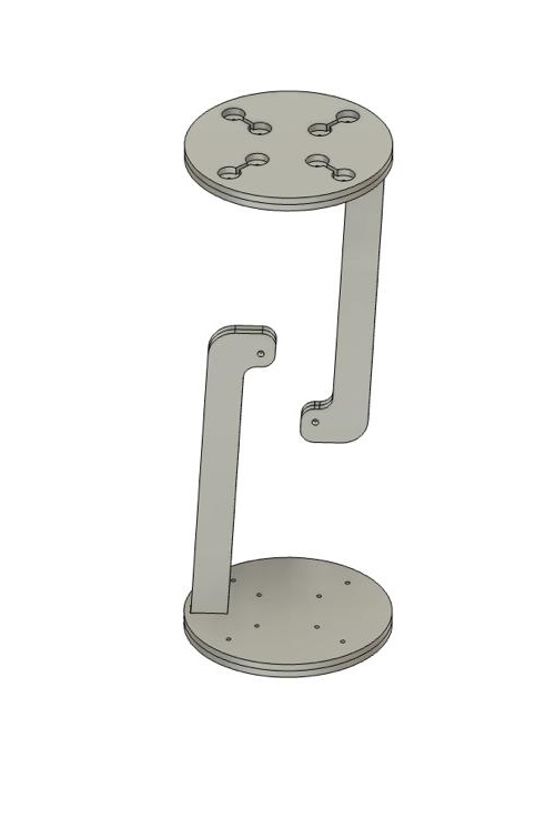
3D design of the floating mirror showing tensegrity structure and mirror integration
Design Process Videos
Design process from side view showing structural development
Design process from front view showing mirror integration
Nifty Dogbone Configuration
Important: When using Nifty Dogbone in Fusion, click the face, not the tab! Input our tool diameter as 0.25 in and clearance as 0.001 in.
Download: Nifty Dogbone for Fusion 360
Note: If using Mac, you may need to go to Privacy and Security settings to unblock the installation. See Autodesk support article for troubleshooting.
Design Requirements
- No sharp edges: Used modify → fillet for all edges that can be cut
- Meter height: Steep angle 500mm legs for total height of ~800mm
- Integrated legs: Made the legs the tables themselves by cutting them into top and bottom surfaces
- Tension cables: 10mm holes in legs for double loops of 4mm cable, two 7mm holes (minimum size cuts) for surface-to-surface tension cables
- Two-layer surface: Upper layer cuts space for finger adjustment and has channel between holes; bottom layer has two holes per cable
2. Computer-Aided Manufacturing (CAM)
CAM workflow following the tutorial video with specific modifications for our project requirements and machine capabilities.
Process Overview
Everything same as in the tutorial video: Anthony's CAM Tutorial
Except for the modifications listed below for our specific project requirements.
Key Modifications
- Create components from bodies: Either in design or manufacturing (nicer workflow)
- 2D contour: Removed lead-in and lead-out for cleaner cuts
- Tab frequency: Reduced to 1 per 5 inches instead of 1 per 3 inches, with manual tabs added where needed
- Arrange setup: Moved to the front to make best use of the stock (instead of center)
Overall Process
- Go to manufacturing tab
- Create components from bodies
- Make a fixed stock manufacturing model with the stock size
- Click modify → arrange on it
- Click the components to arrange them on the stock
- Set up parameters for 2D contours per edge mill (big size and small size, so two tool paths)
- Generate the .ncl files (numerical control files)
- Machine takes .tap which is a postprocessed .ncl file
Note: The .tap extension is a historical carryover from the era of tape-driven machinery. Early numerical control (NC) machines used perforated paper or card stock, known as "tape," to store and transfer program data.
3. Small Model for Assembly
Testing assembly process and configuration using 3D printed models to validate design before CNC machining.
3D Printing Process
I 3D printed both altogether which failed and also printed flat as the output of the machining process to test the assembly. I used glow in the dark PLA!
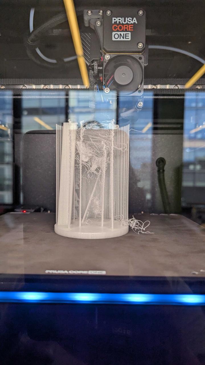
Initial 3D print attempt showing failure mode
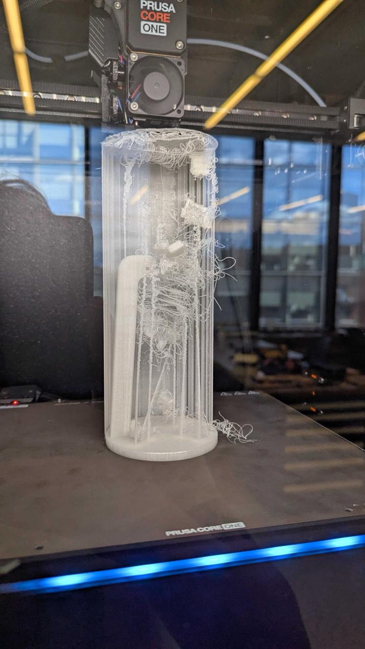
Failed print result highlighting design issues
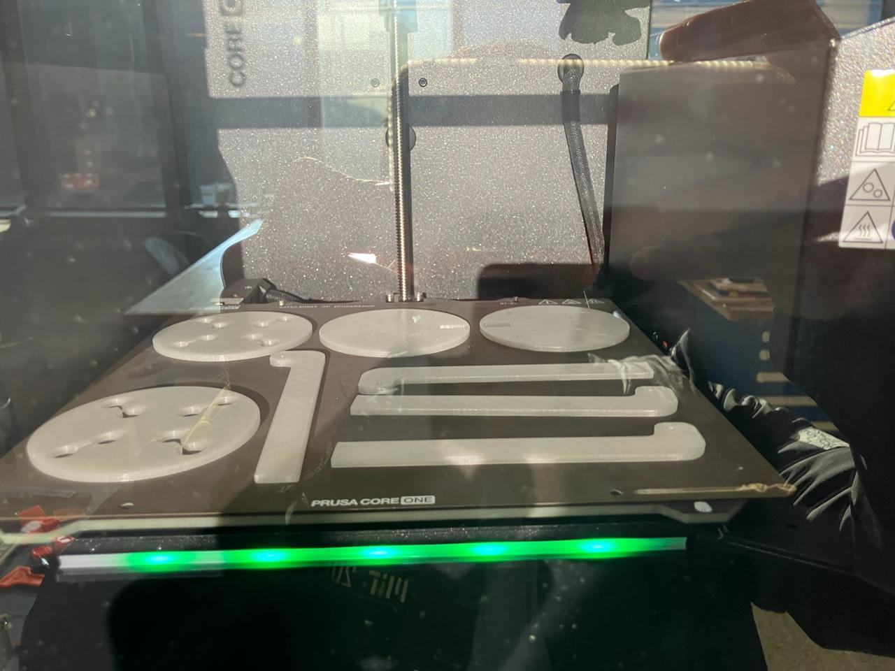
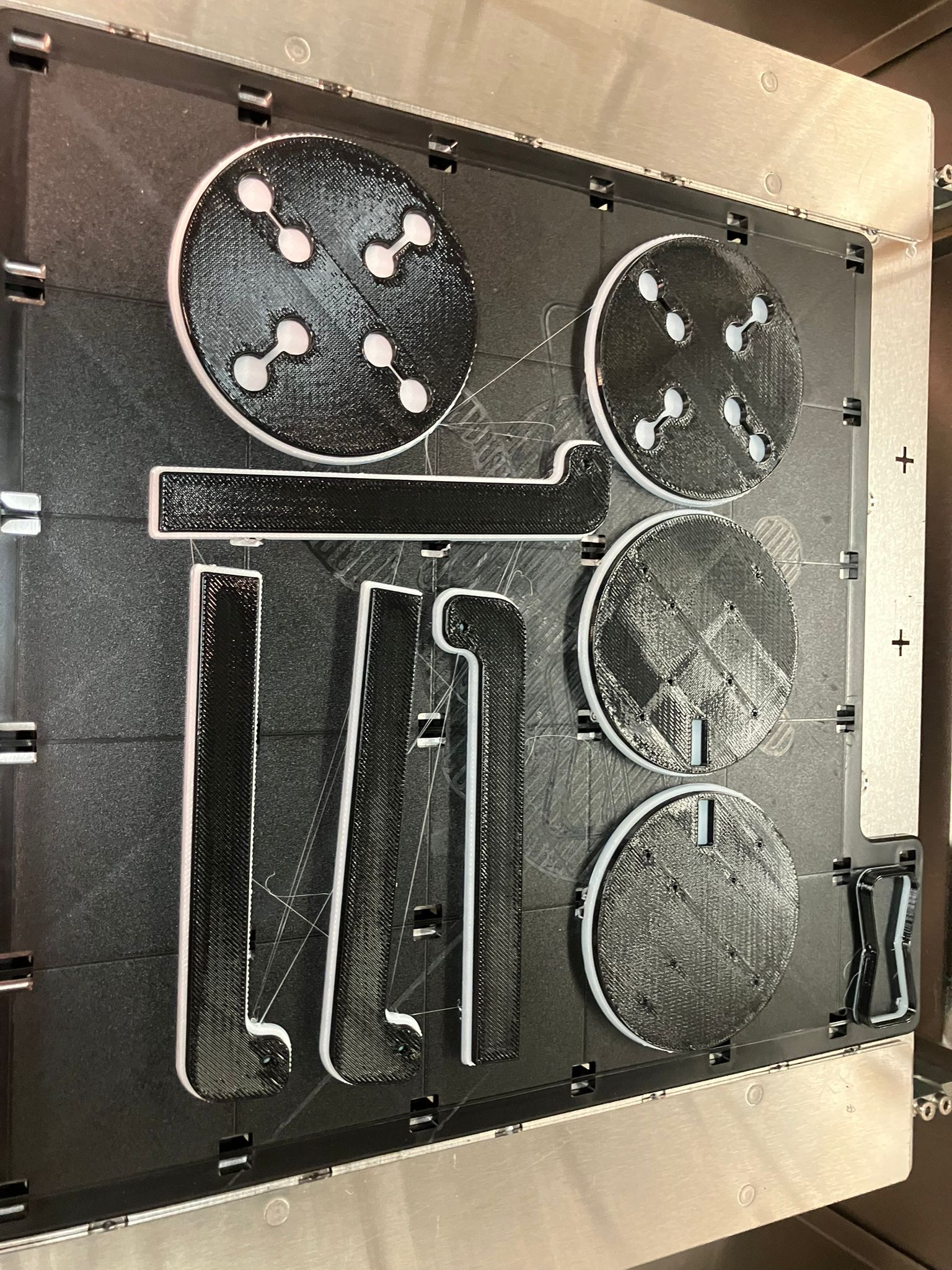
Successfully printed parts for assembly testing
Stratasys Printing
Slice and print on Stratasys software, dissolve support, then remove and wash parts after support is dissolved.
Stratasys print in progress with support material
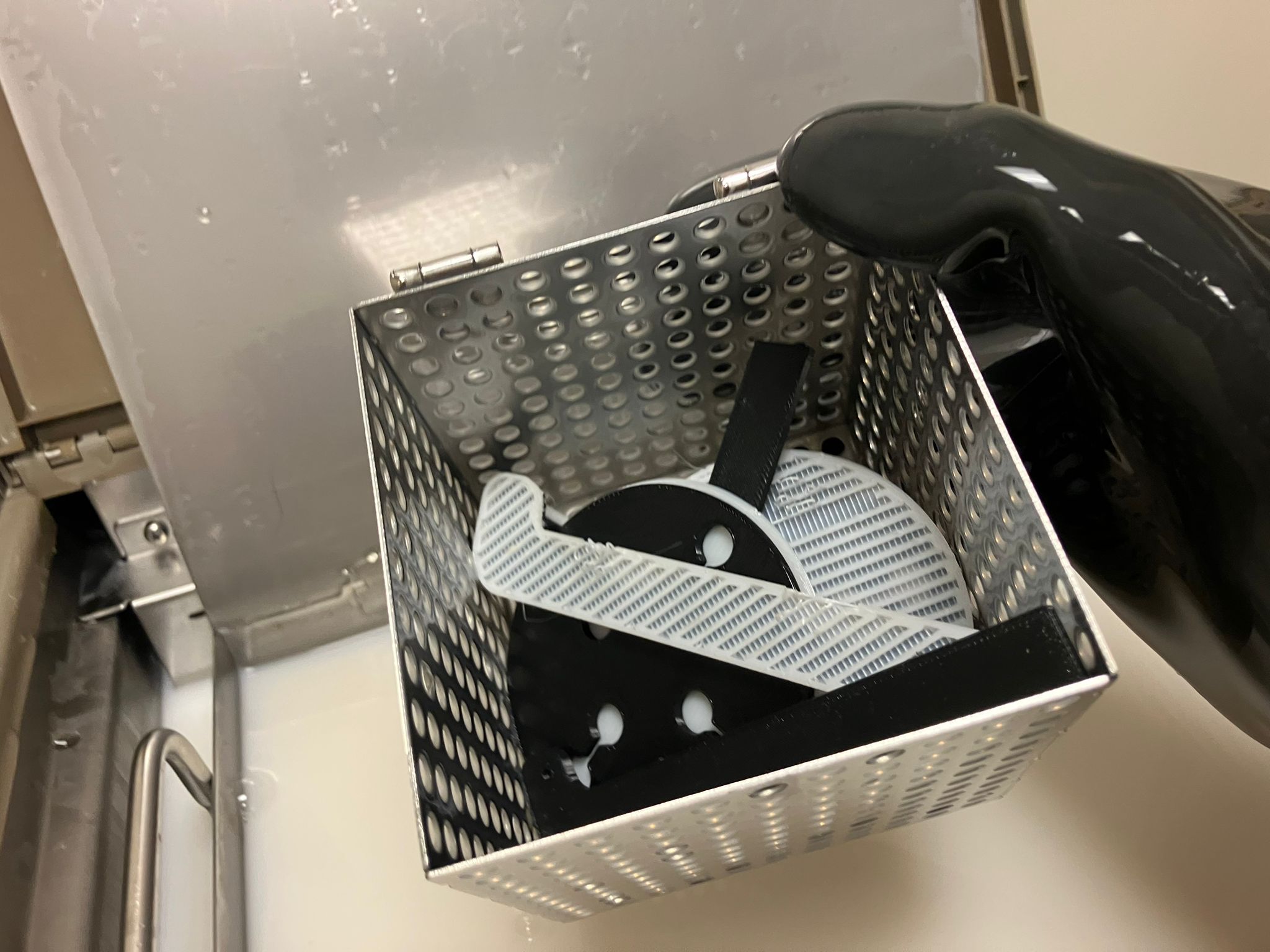
Dissolving support material in solution
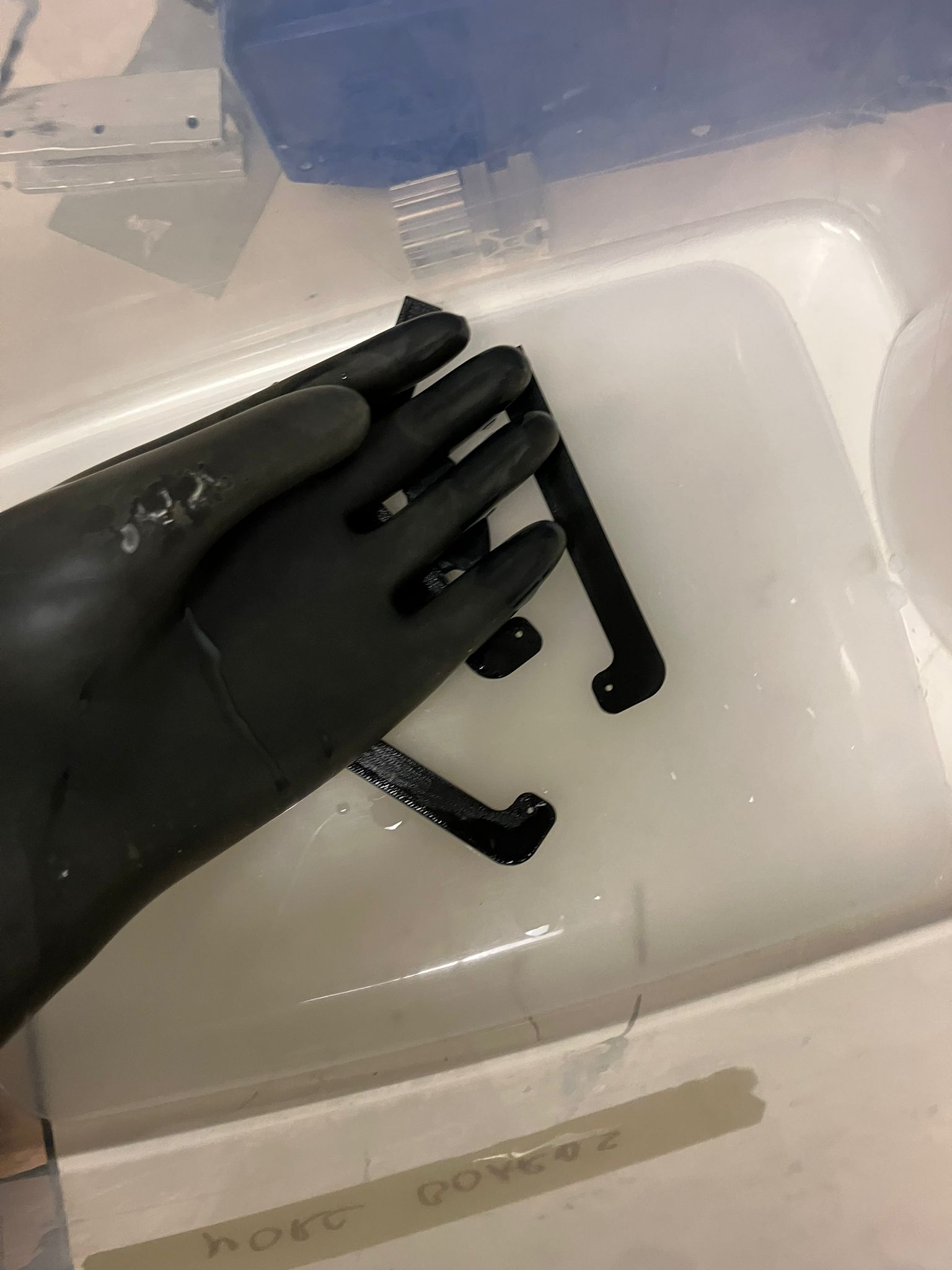
Cleaned parts after support material dissolution
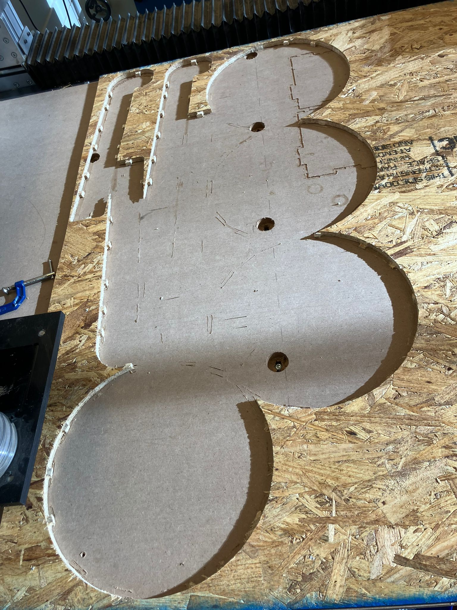
4. Cutting
CNC machining process with careful attention to safety and proper tab removal techniques.
Machining Process
Run the job with care (see training section for details). When removing tabs, use the battery-powered flat drill. For the circles, drill off both sides of the tabs, then use a crow bar gently around the perimeter until it pops off.
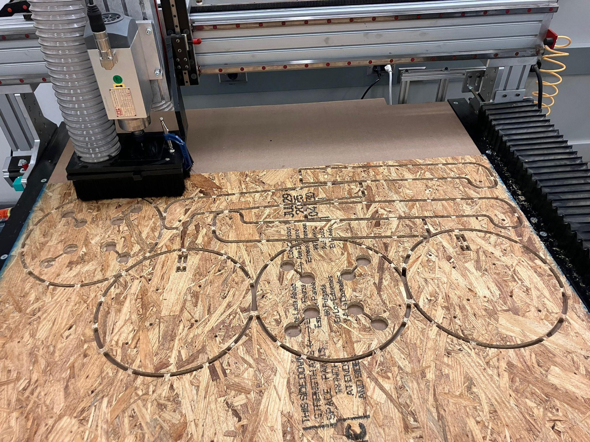
CNC machining process showing wood cutting operation
Completed cut parts ready for assembly
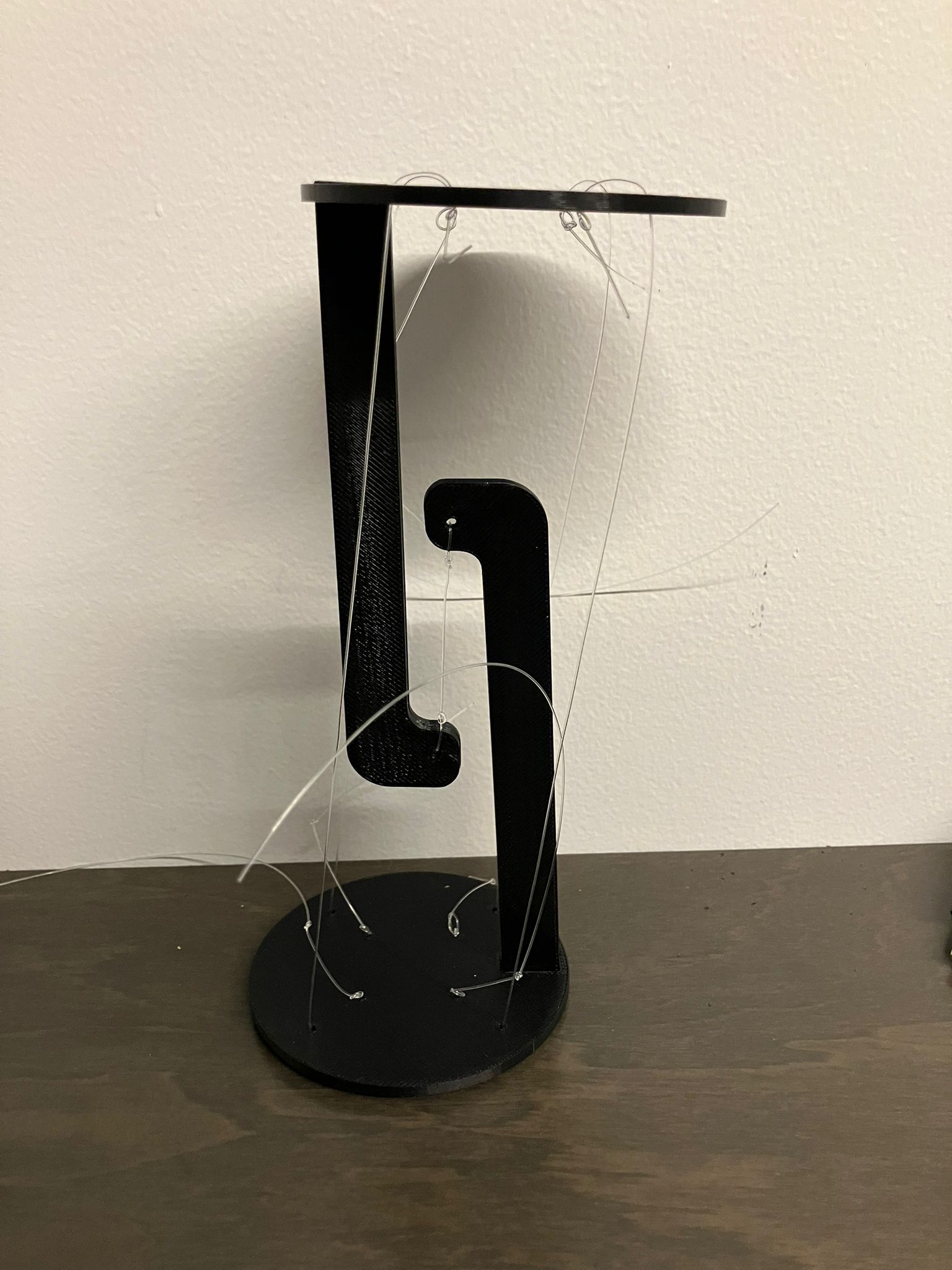
5. Assembling
Part 1: Assembling 3D Printed for Right Configuration
Testing tension cable ratios and angles using 3D printed components. We used fishing rod line because it's mostly transparent and makes the levitation effect more effective as shown in this Instructables guide, especially when imaged in night mode as glow in the dark assembly!
Prusa CoreOne Assembly
Testing tension cable ratios and angles using 3D printed components with glow-in-the-dark PLA for enhanced levitation effect.

Glow-in-the-dark assembly in night mode showing levitation effect

Color testing of the glow-in-the-dark components
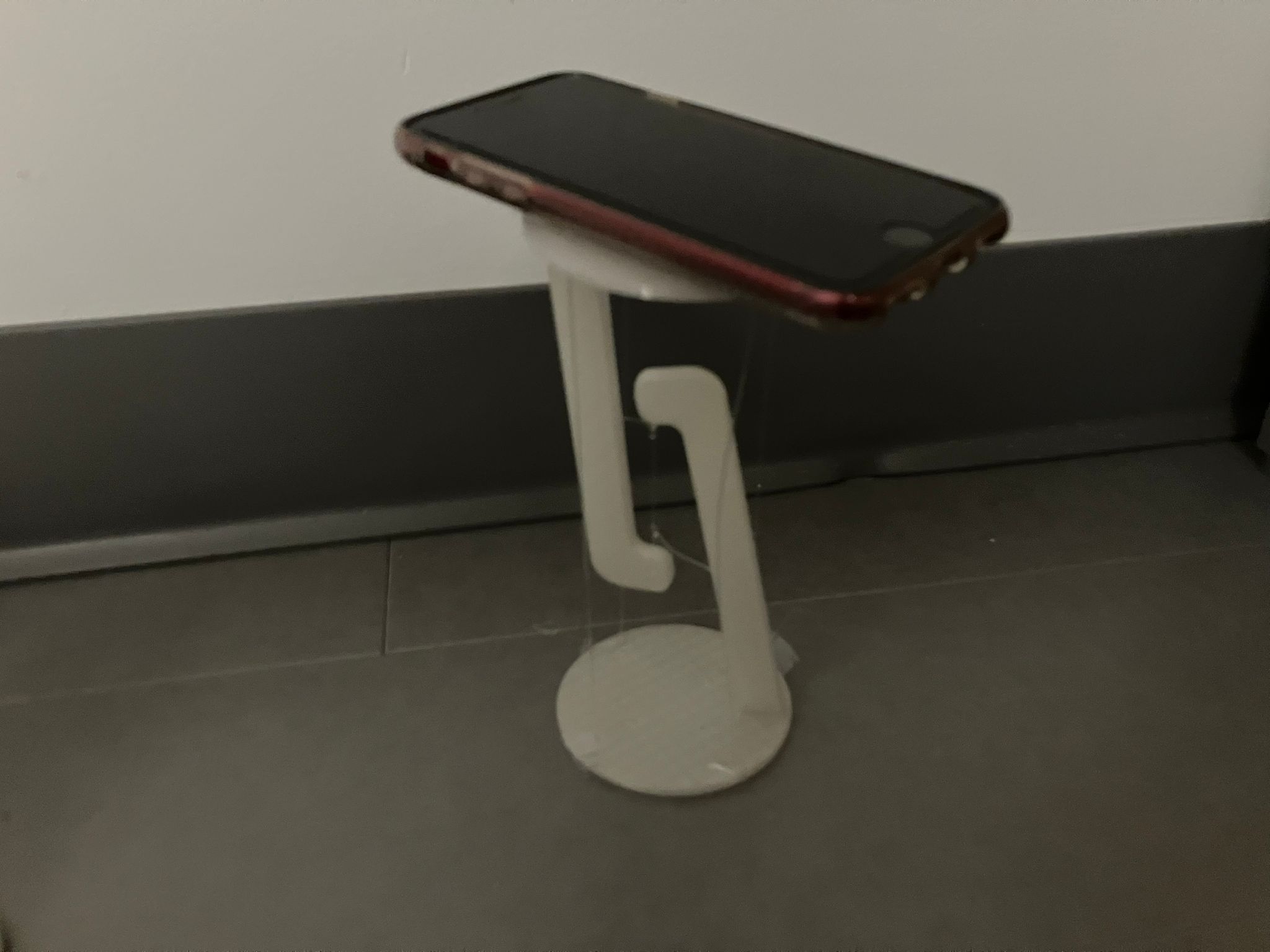
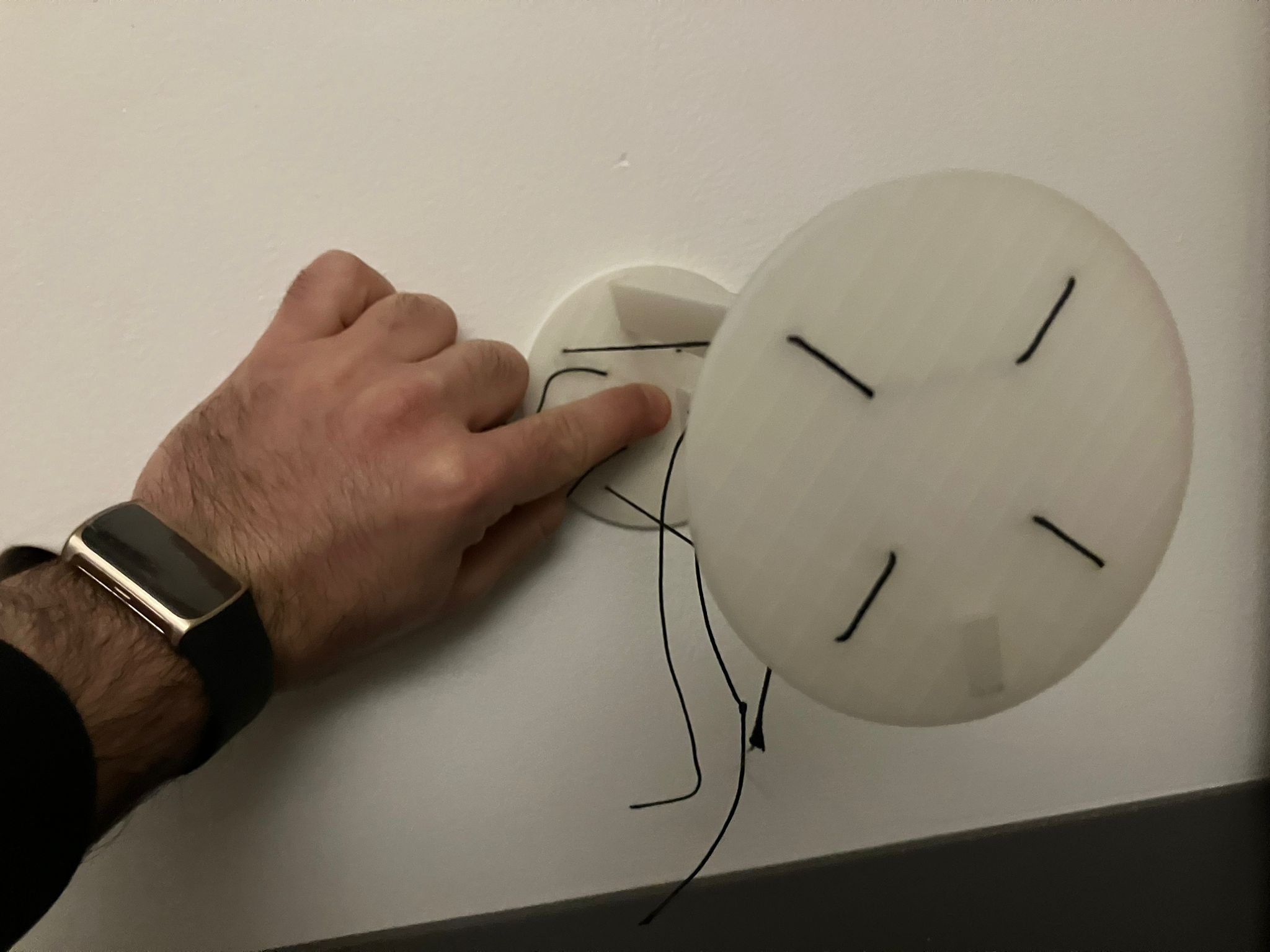
Phone testing of the floating mirror assembly
Wall-mounted floating mirror demonstration
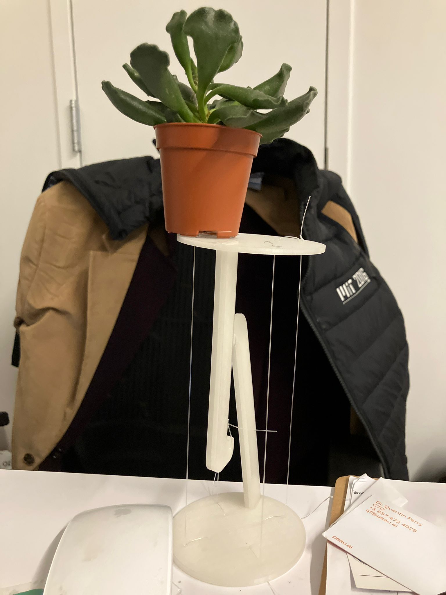
Succulent plant test showing the assembly can hold plants
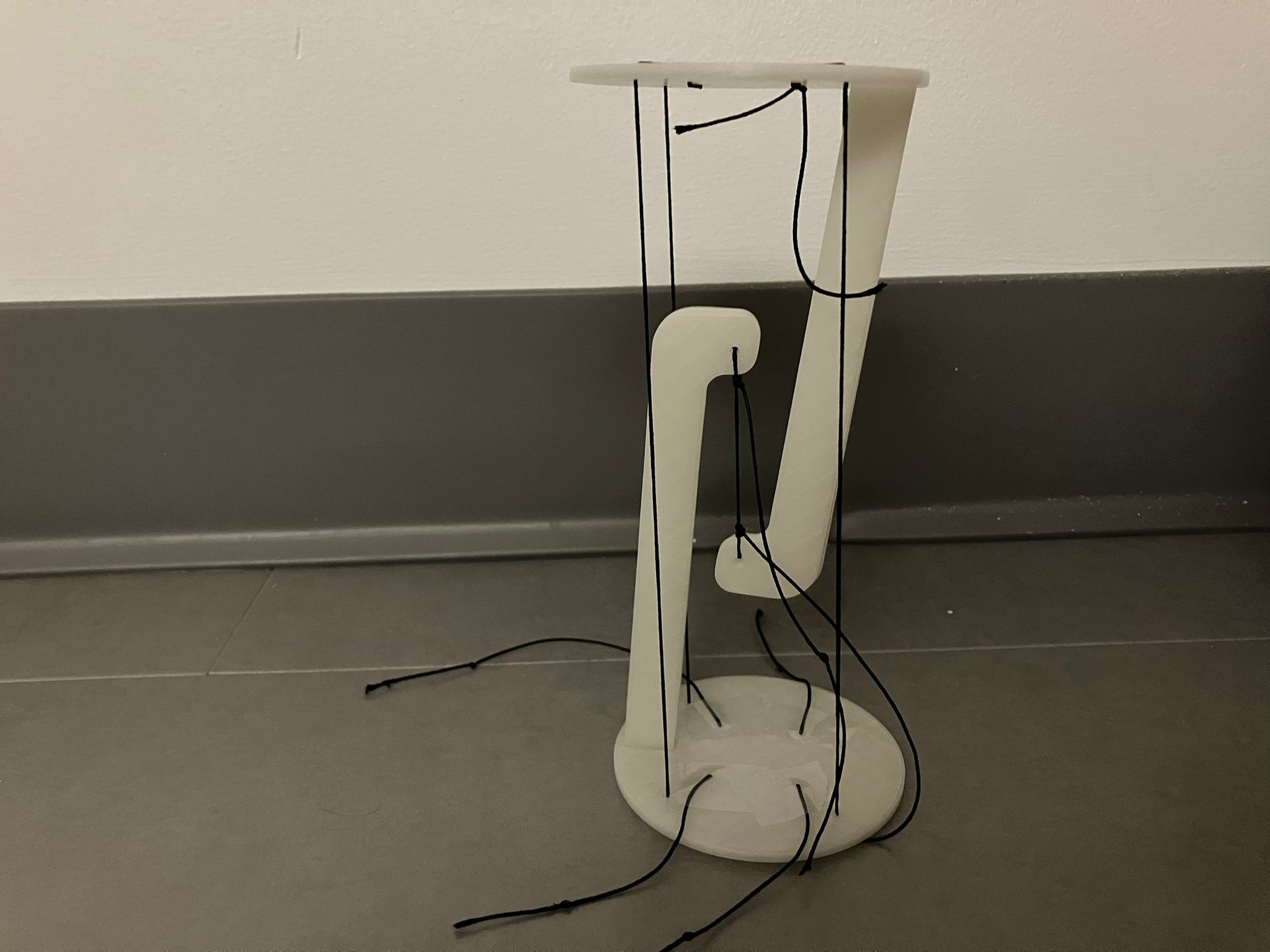
Kevlar Assembly
Initial threading used a sewing needle; the Kevlar line fractured the needle, so we re‑threaded using a smaller carrier thread. The assembly was completed and wall‑mounted. For rapid iteration we temporarily set tension with tape; for final installations, secure with knots to eliminate slip and creep.
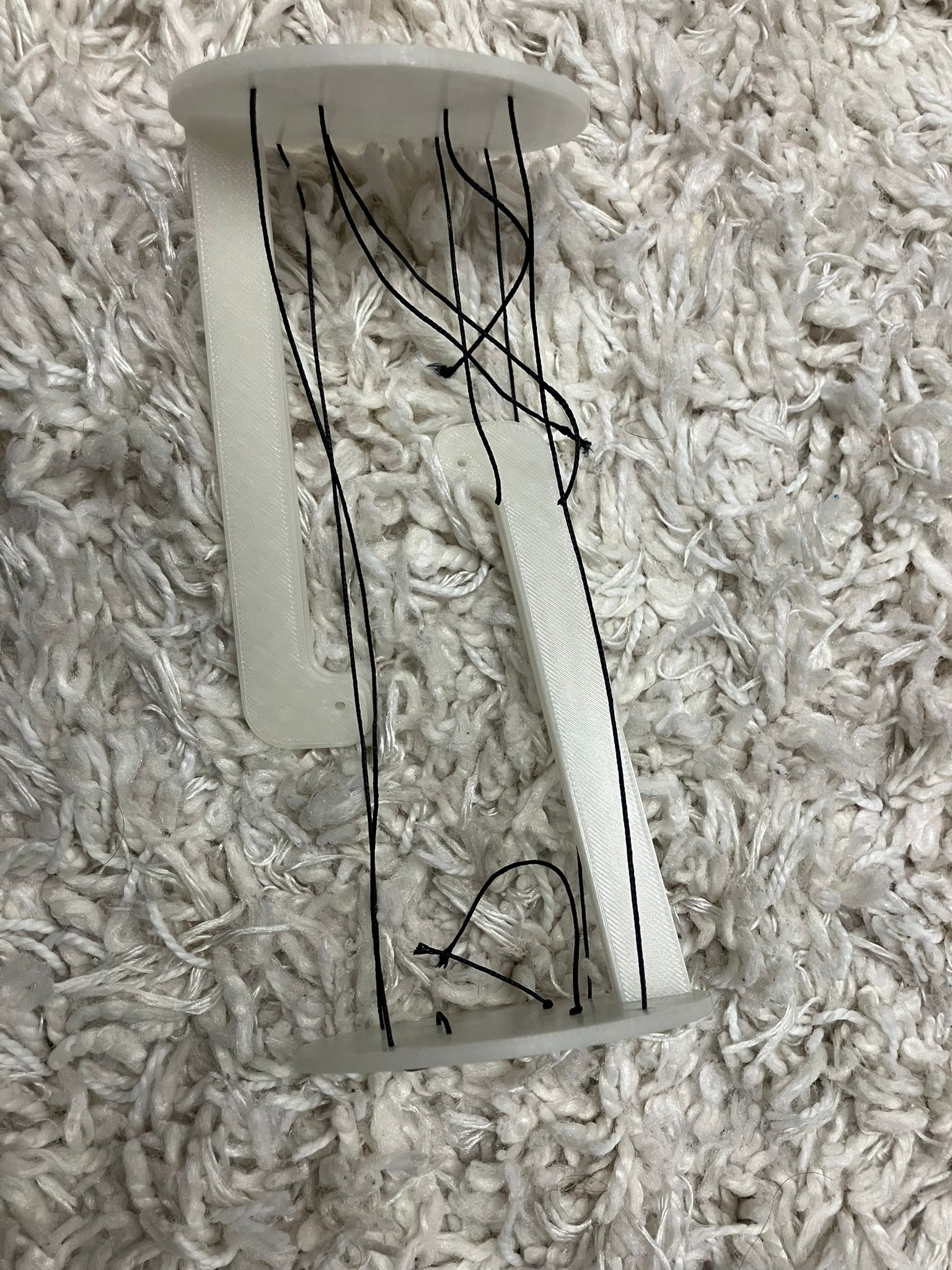
Fully threaded Kevlar assembly with smaller thread
Completed Kevlar tensegrity assembly
Kevlar threading process demonstration
Wall-mounted Kevlar tensegrity assembly
Stratasys Assembly
Assembled with only knots because tape doesn't work on Stratasys printed filament -- works even better than tape anyway.
Stratasys assembly using only knots for tension cable attachment
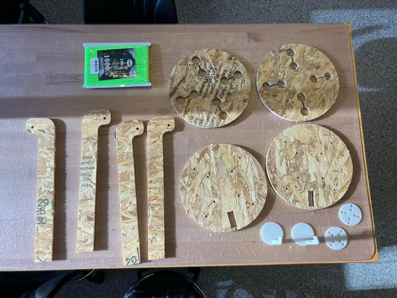
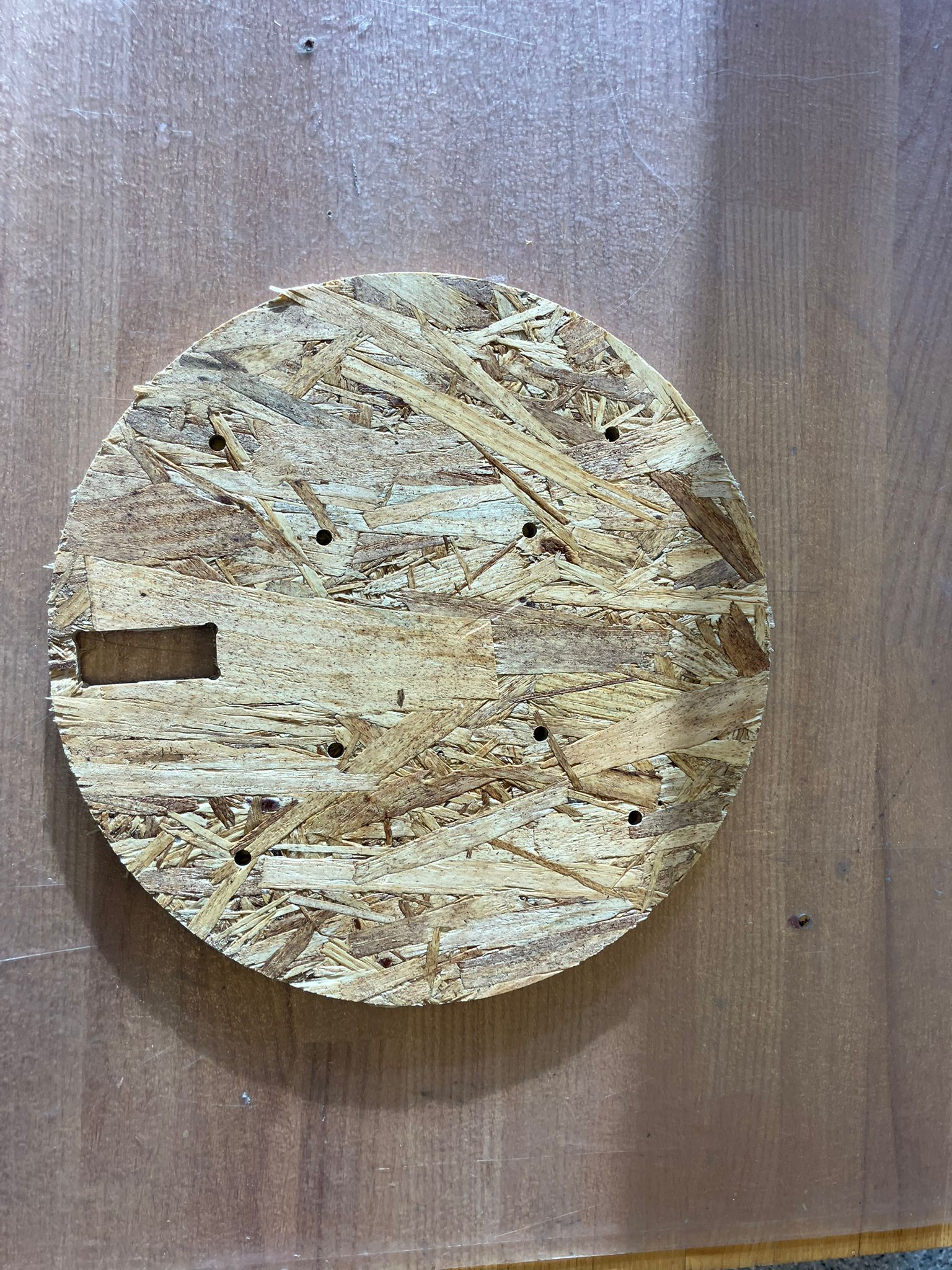
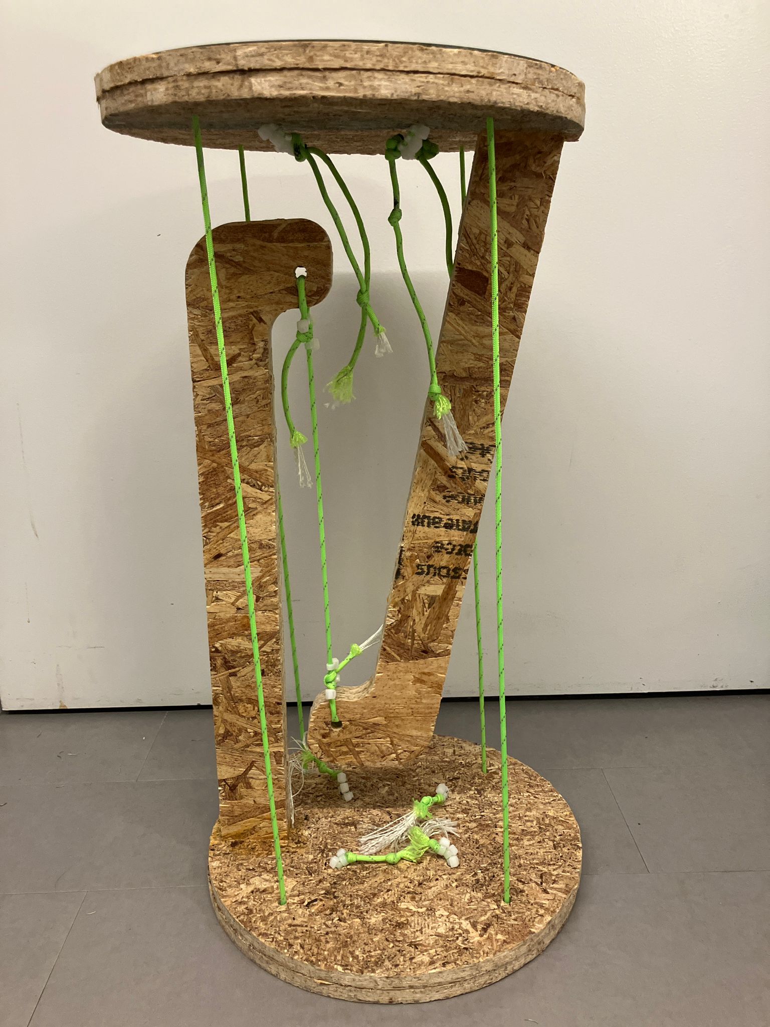
Part 2: Assembling OSB (Oriented Strand Board)
What is OSB? Oriented Strand Board is an engineered wood product made from layers of wood strands (or wafers) bonded together with resin and high heat. The strands are "oriented" in specific directions, and each layer is aligned in various directions to enhance the board's strength and stability. It is a popular, more affordable alternative to plywood for applications like sheathing and subflooring.
Here we're using 1000ft-rated 4mm paracord from Amazon for the tension cables.
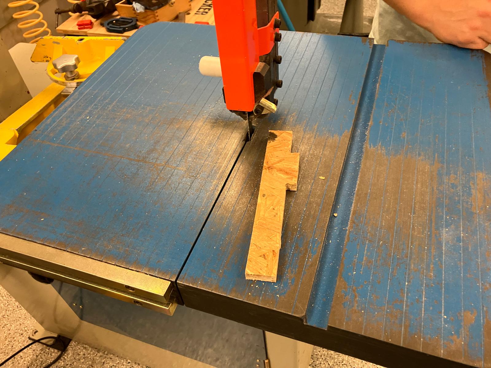
1. Removing Parts After Machining
- Use a small saw tool to cut through the tabs connecting the machined parts to the stock material
- Apply full pressure with the saw tool, positioning the blade as close to the part edge as possible for clean cuts
- For circular parts, cut through both sides of the tab to ensure complete separation
- After cutting the tabs, use a crow bar to gently pry up the part, working around the perimeter until all plastic nails are released from the stock
- Carefully remove the part from the CNC bed, ensuring no damage to the machined surfaces
Cutting tabs with saw tool for part removal
Tab removal process demonstration
Cleaning the CNC bed with vacuum after part removal
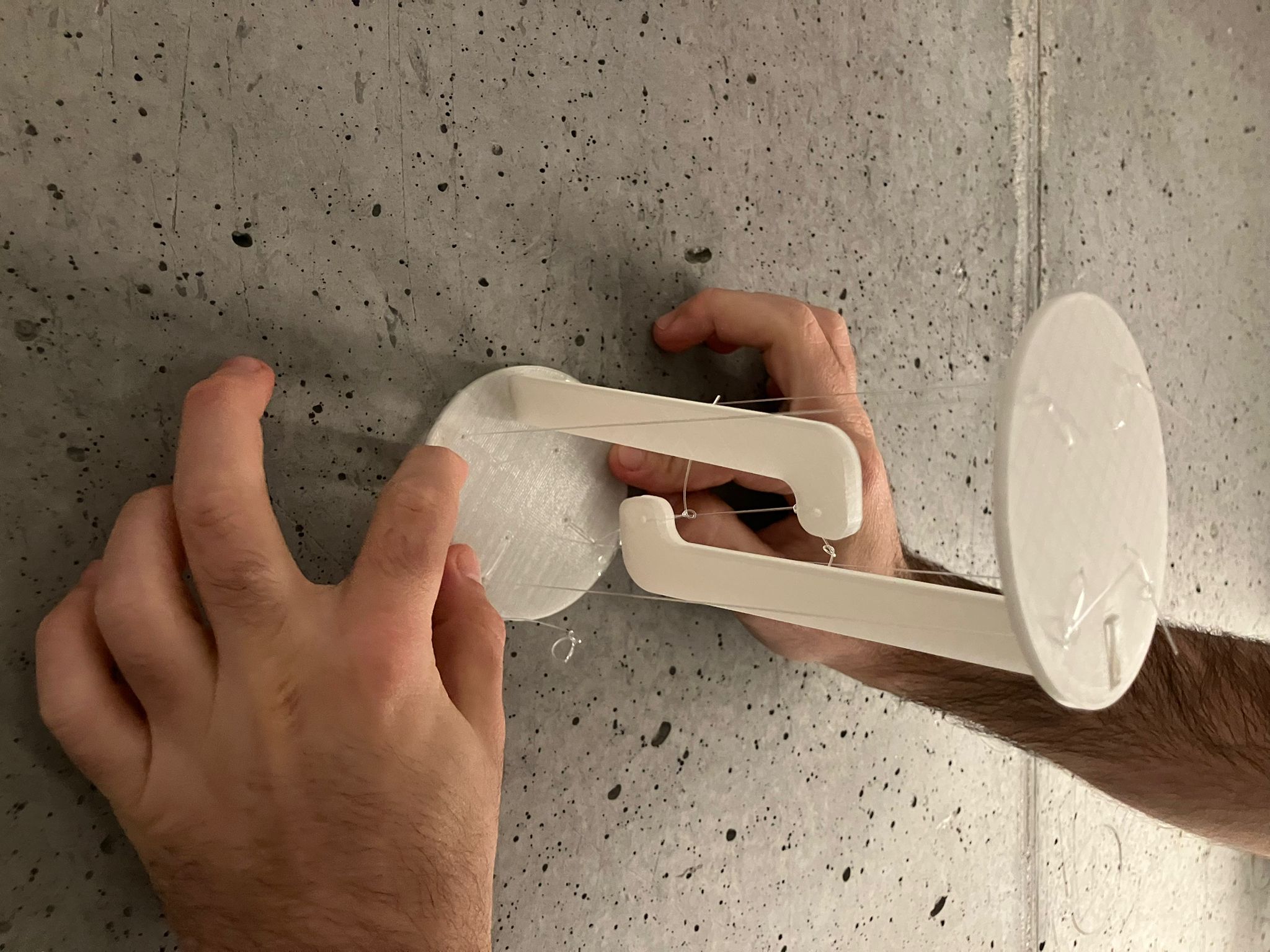
2. Assembling Without Glue
- Use a file to refine the press fit joints until they insert smoothly into the dogbone holes with a snug, secure fit
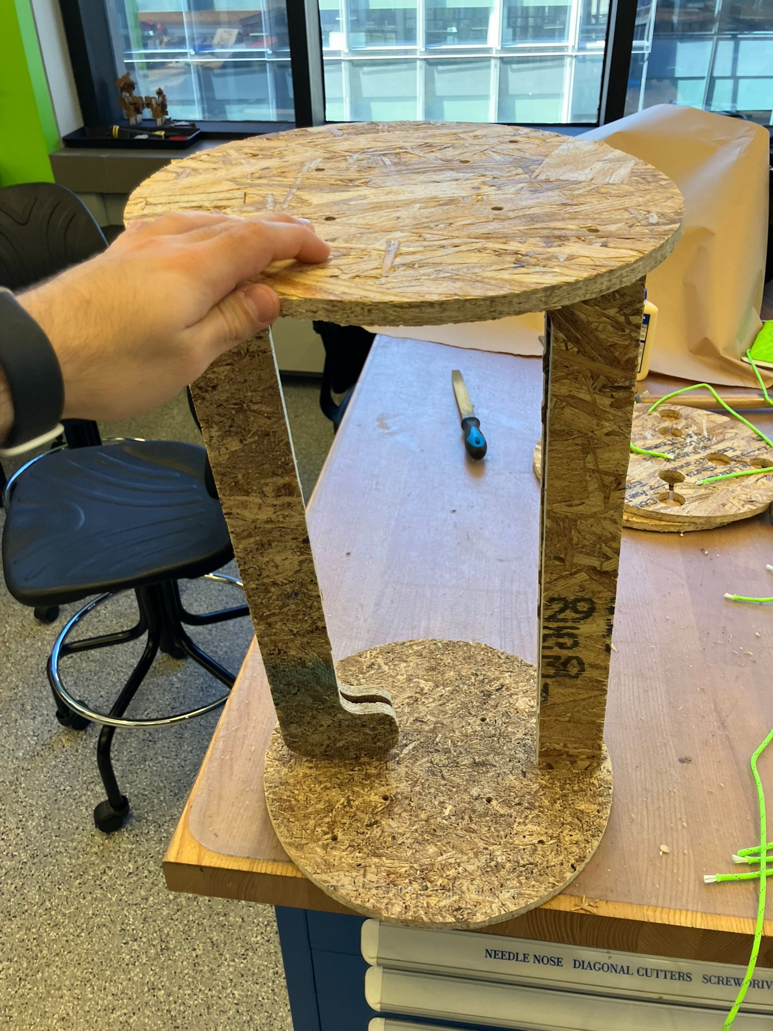
- Insert the leg components into the circular bottom panels, aligning with the pre-drilled paracord holes
- Thread the paracord through the edge holes, ensuring proper alignment for the tension system
- Route the paracord in a straight line across the top surface to the corresponding inner circle hole, then thread back to the leg side
- Repeat this threading pattern for all four corner holes to establish the complete tension network
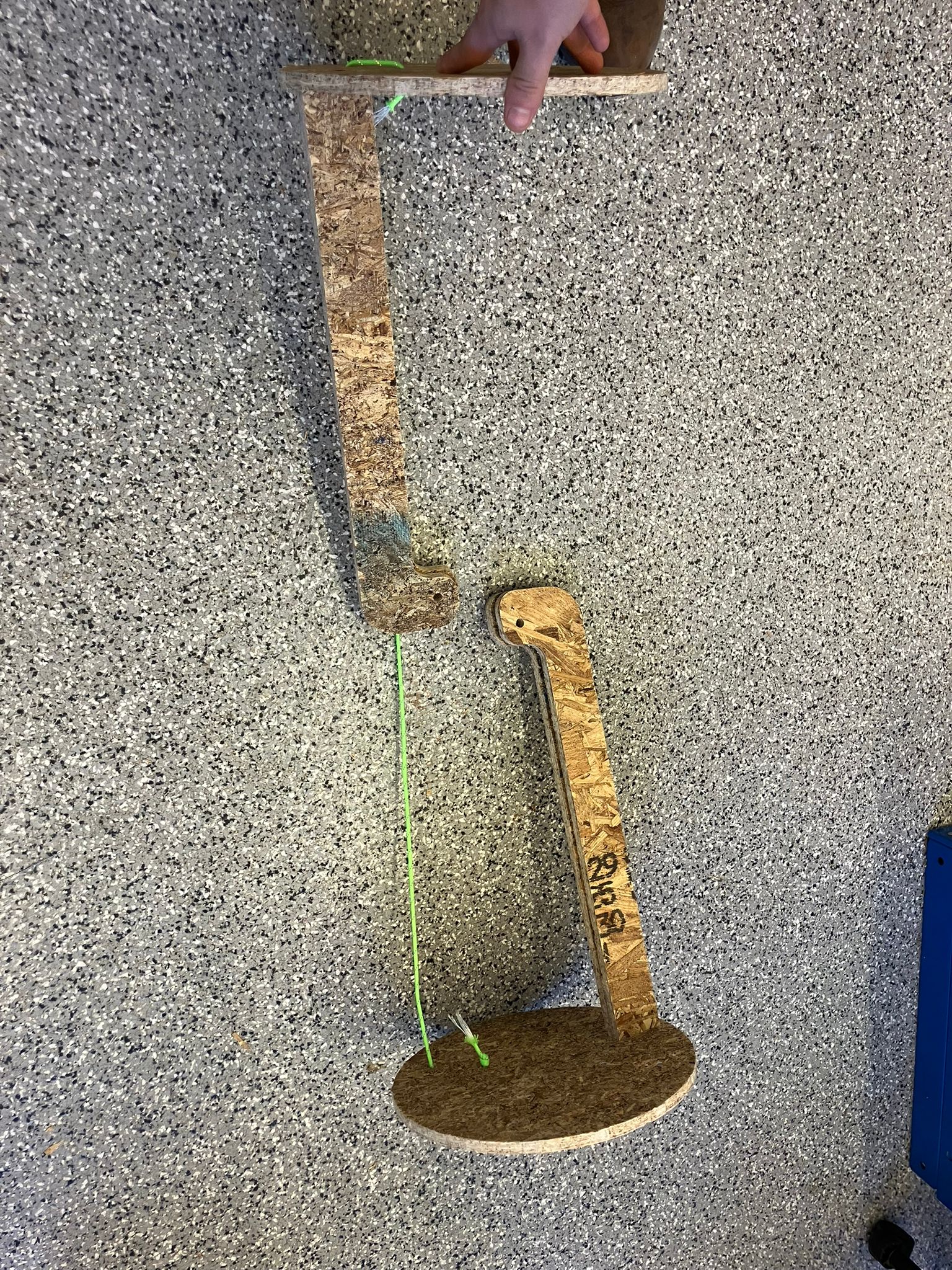
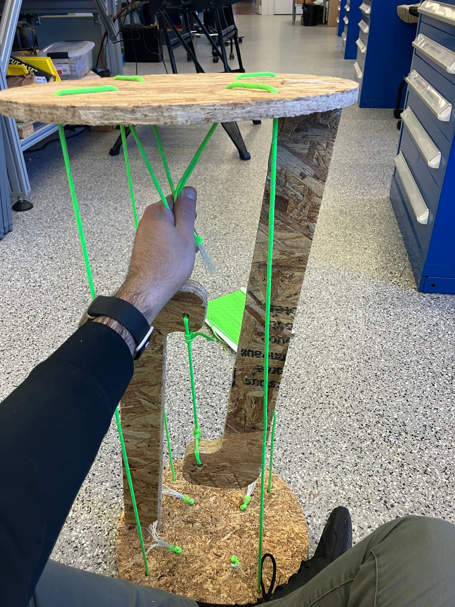
- Insert paracord between the two leg assemblies and adjust tension to achieve the desired vertical or semi-vertical spacing
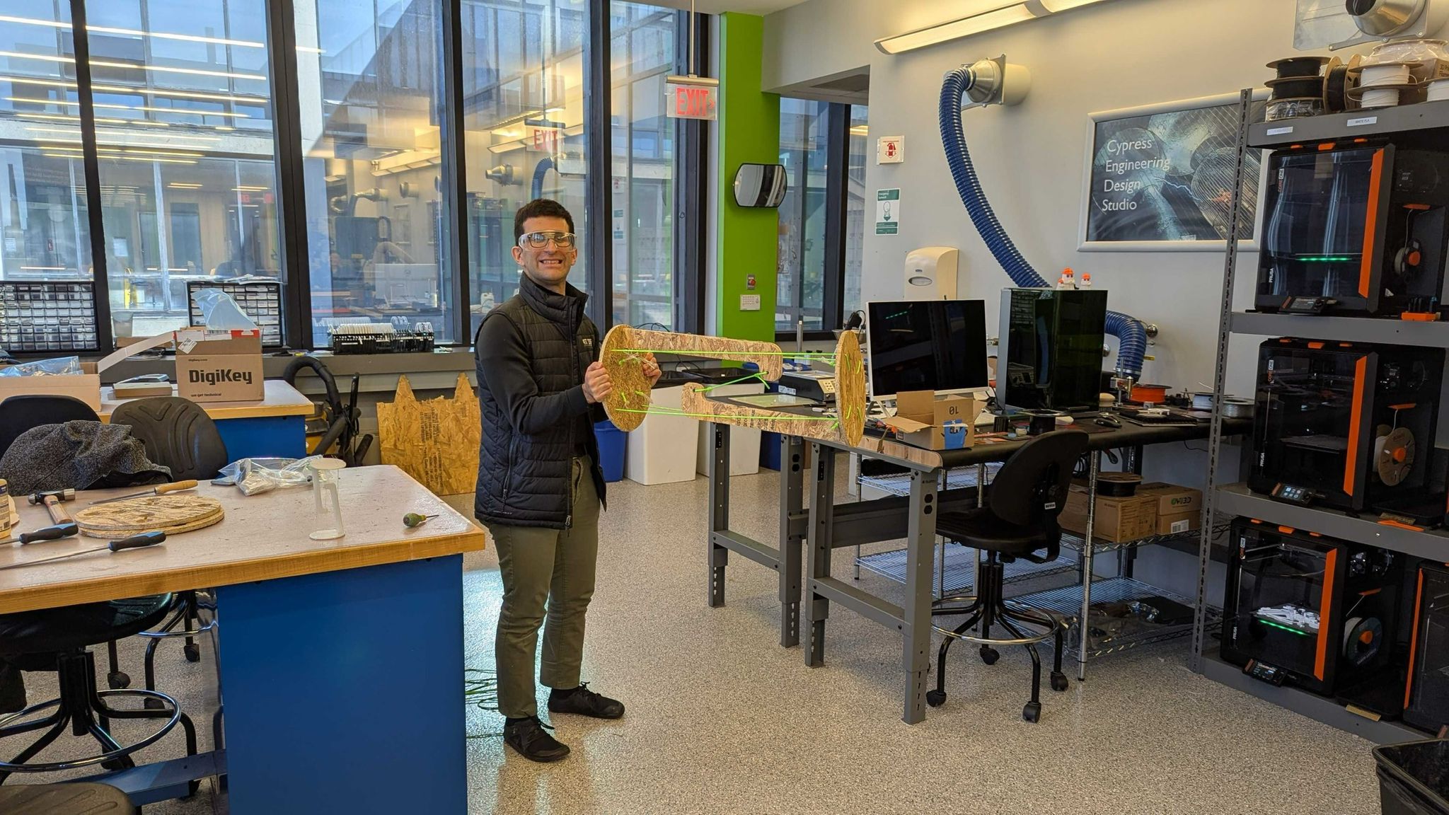
- Lift the assembly from the top and adjust paracord tension until achieving a stable, balanced floating configuration
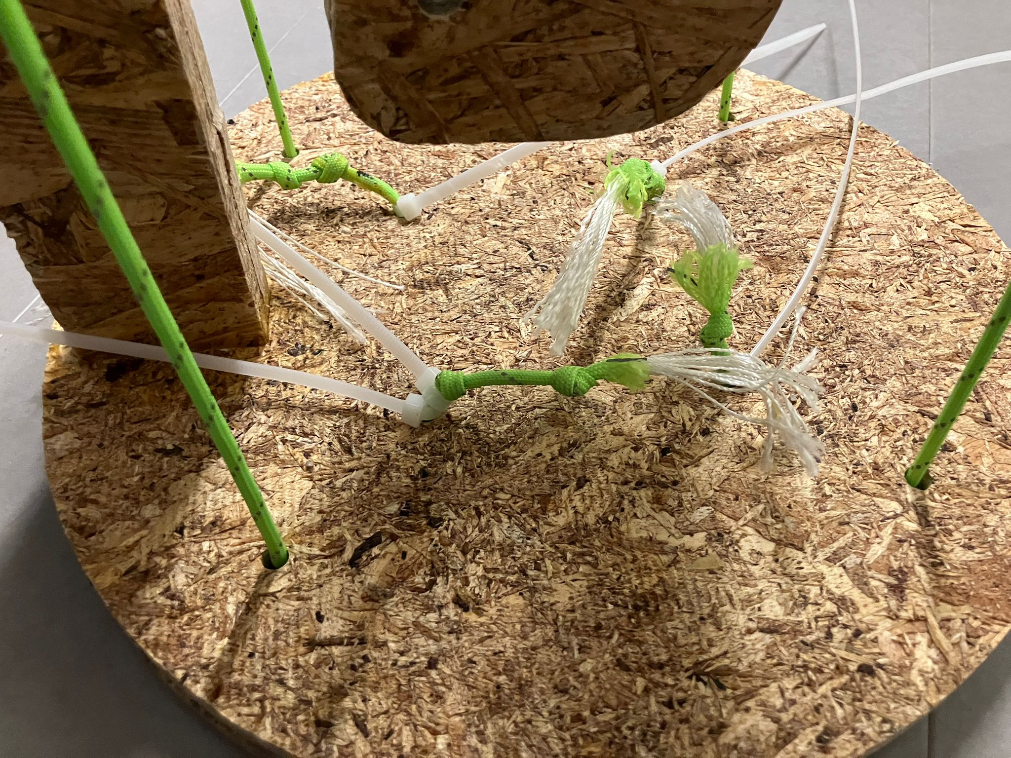
- Mark the optimal knot positions using a permanent marker or ziptie for reference
- Lay both subsystems horizontally on a flat surface and tie secure knots at the marked positions
- Secure each knot with zipties positioned between the knot and hole to prevent slippage and maintain tension integrity
- Trim excess ziptie material flush with the knot for a clean, professional appearance
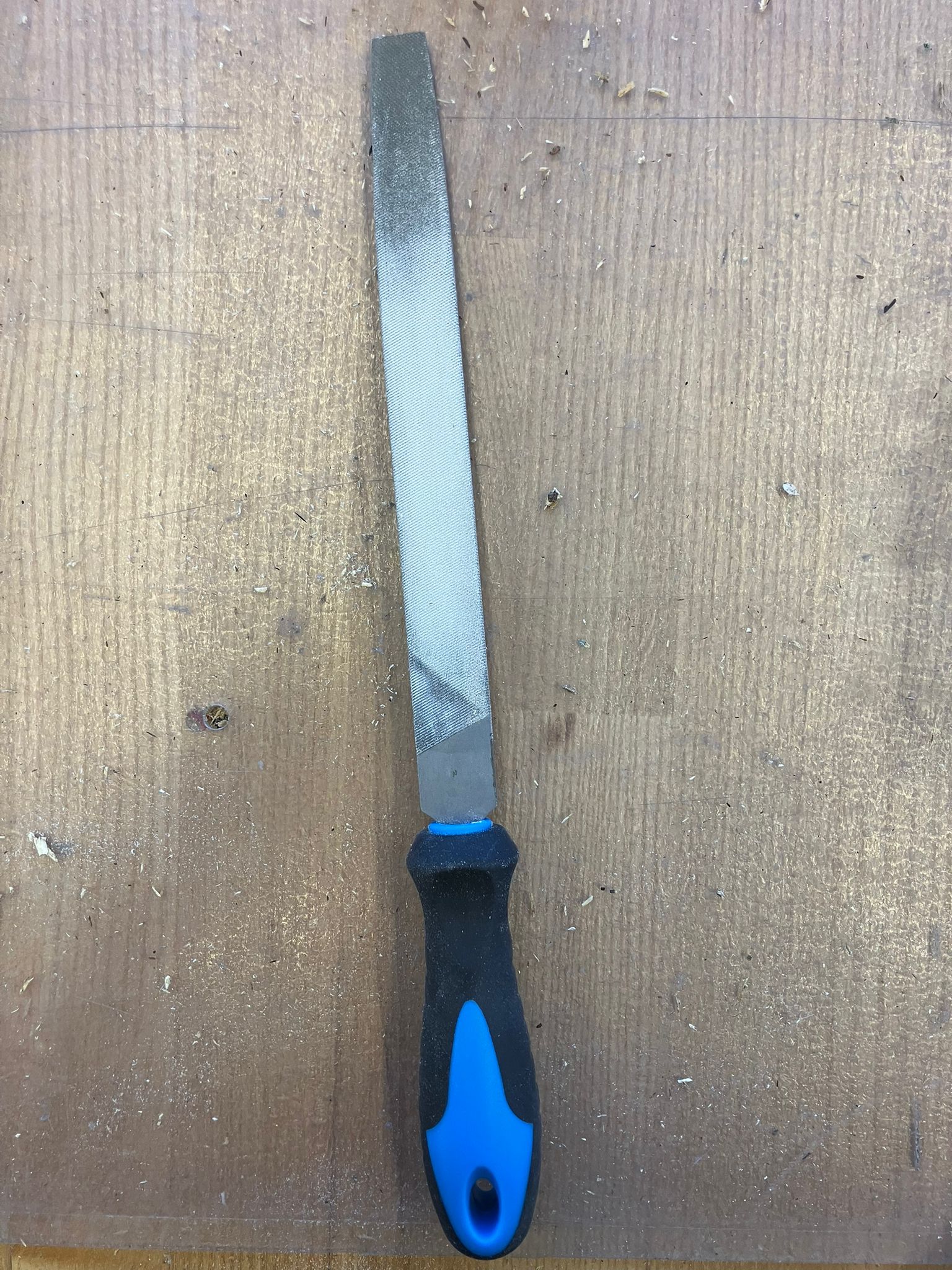
Filing joints to achieve proper press fit
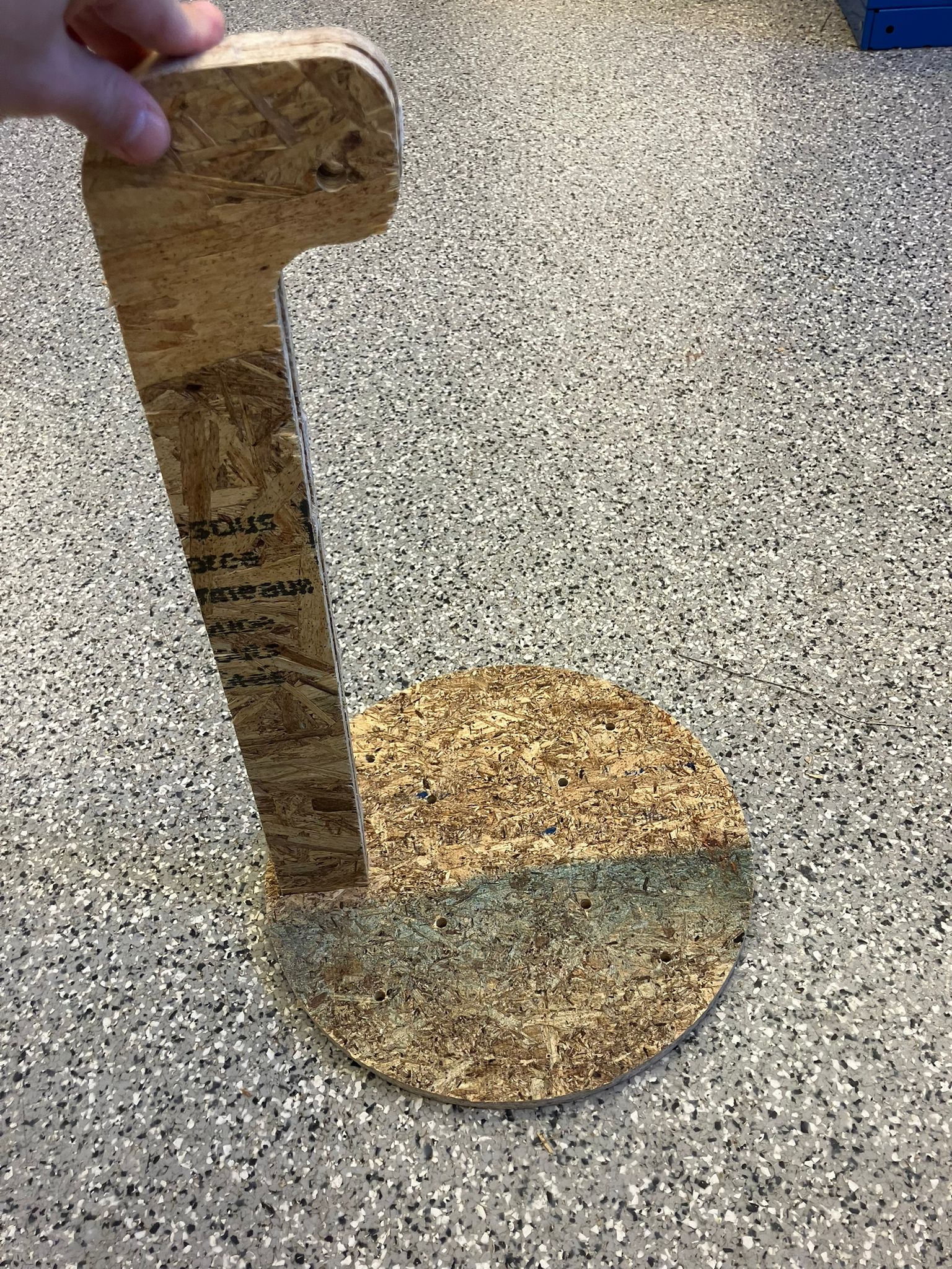
Inserting leg into circular bottom panel
Threading paracord through edge holes
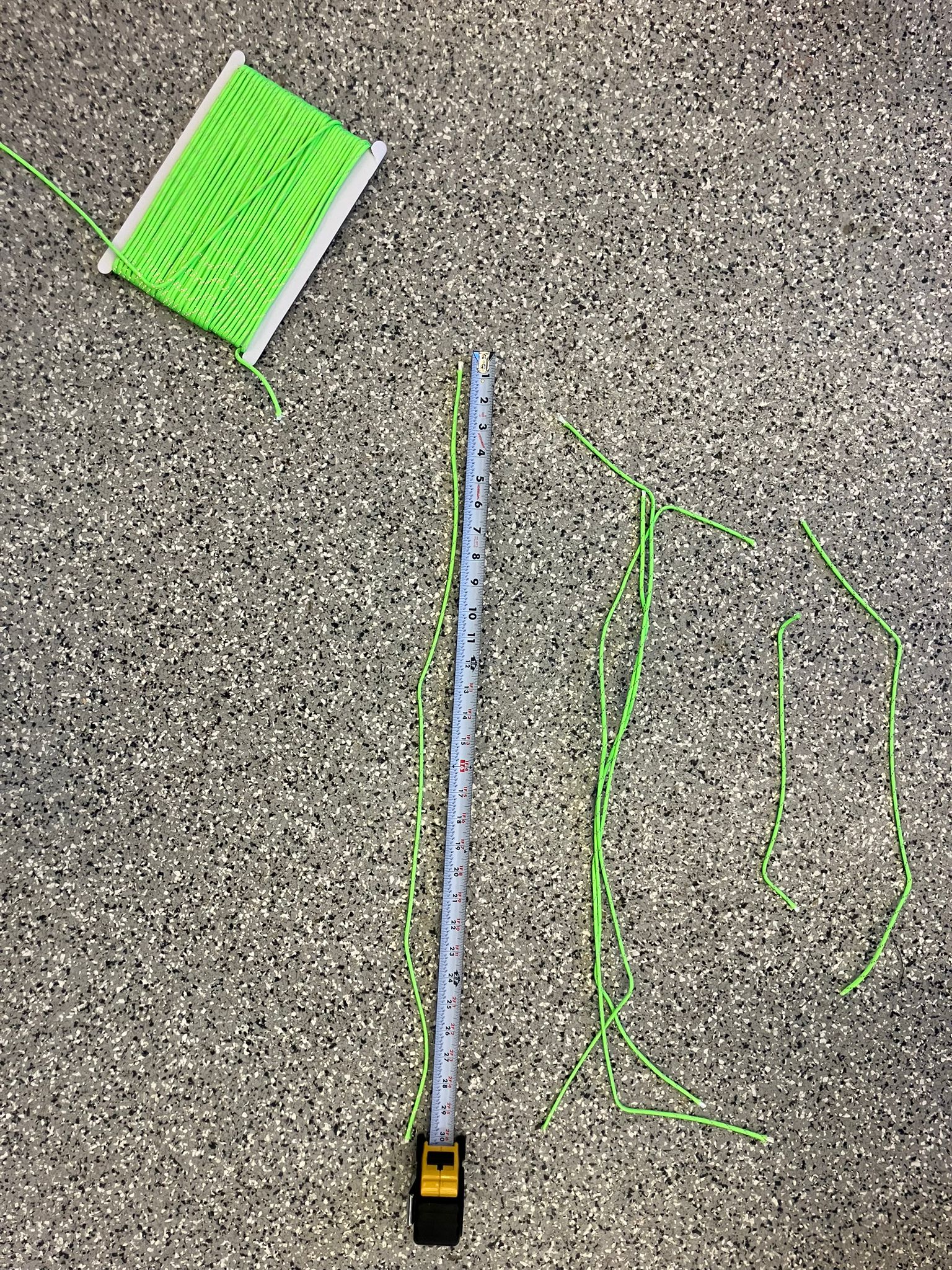
Measuring paracord for proper tension
Tightening paracord to marked position
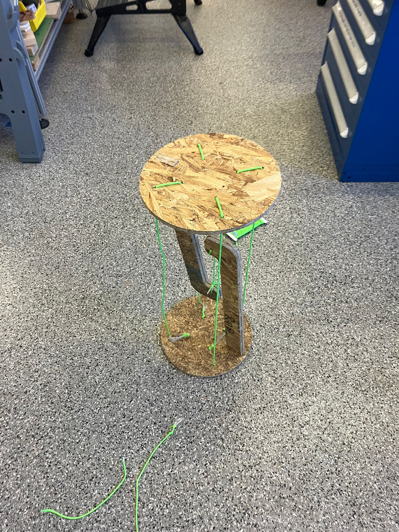
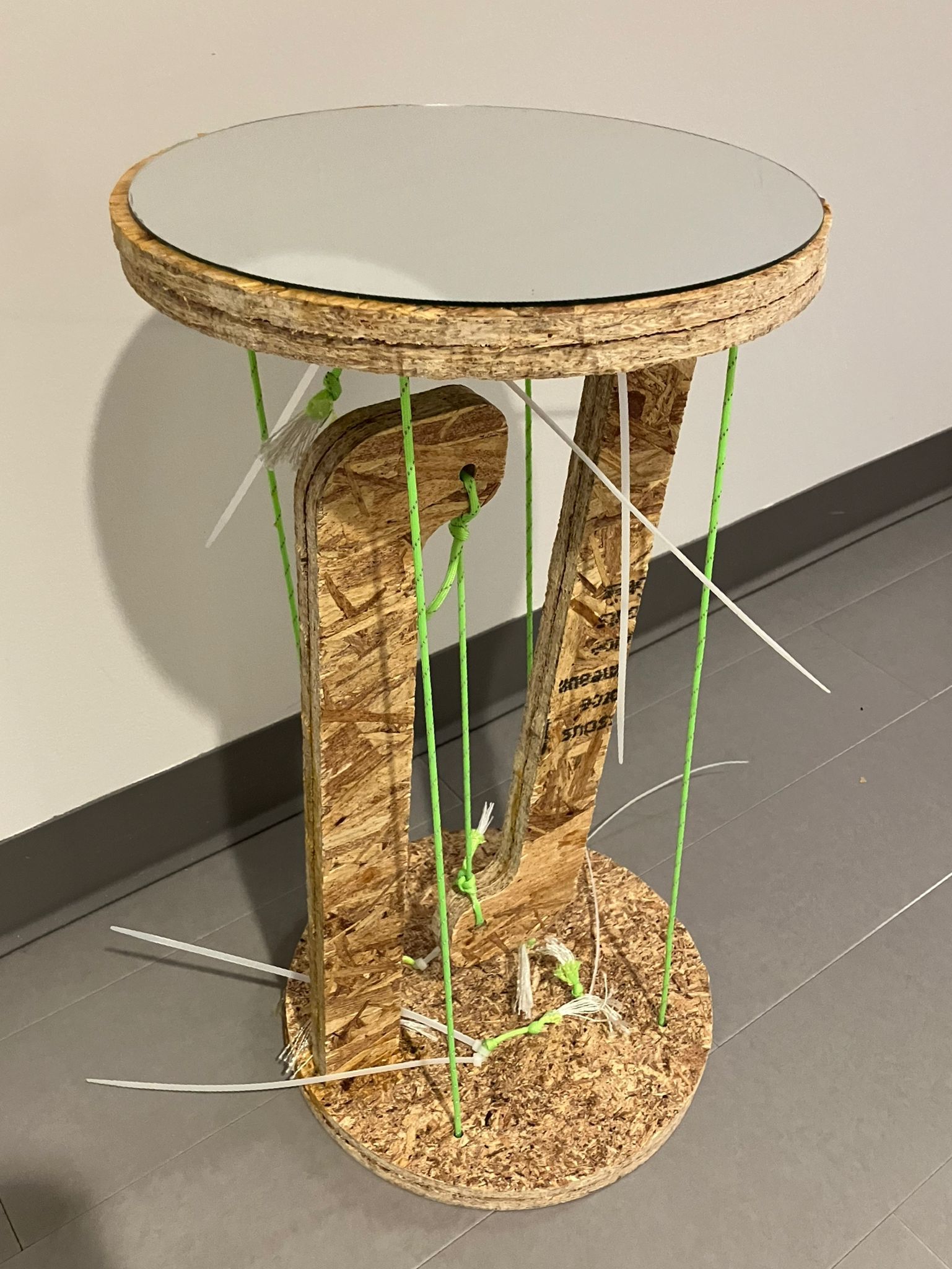
Completed assembly without glue
Horizontal assembly configuration
Holding floating configuration from top
Horizontal assembly without glue showing stability
3. Gluing for Mirror
- Prepare the work surface with protective paper to prevent glue contamination and ensure easy cleanup
- Gather an adequate number of clamps to secure all joints during the gluing process
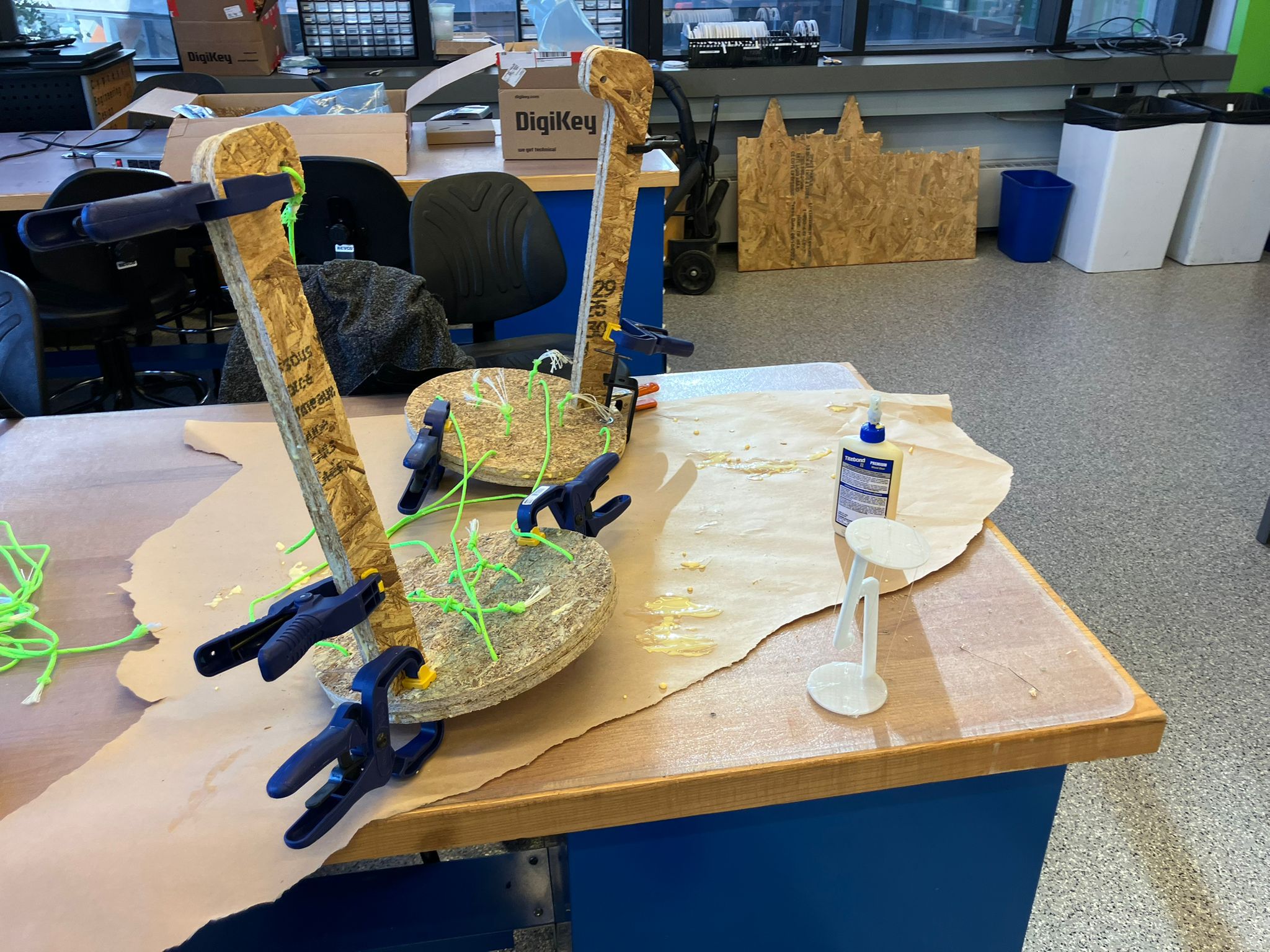
- Apply wood glue around the press fit joint edges and within the joint interface to reinforce the connection for horizontal wall mounting applications
- Position clamps at the critical edge locations between the leg and circle perimeter, as this area represents the weakest structural point and is most susceptible to failure under horizontal stress
- Apply adhesive to the mating surfaces of the upper and lower circles, taking care to minimize contact with paracord channels (any excess glue can be removed and cleaned up later)
- Carefully position the second layer components onto the upper and lower circles, ensuring paracord routing remains unobstructed through the designated channels
- Secure the glued layers with clamps, applying even pressure across all joint surfaces
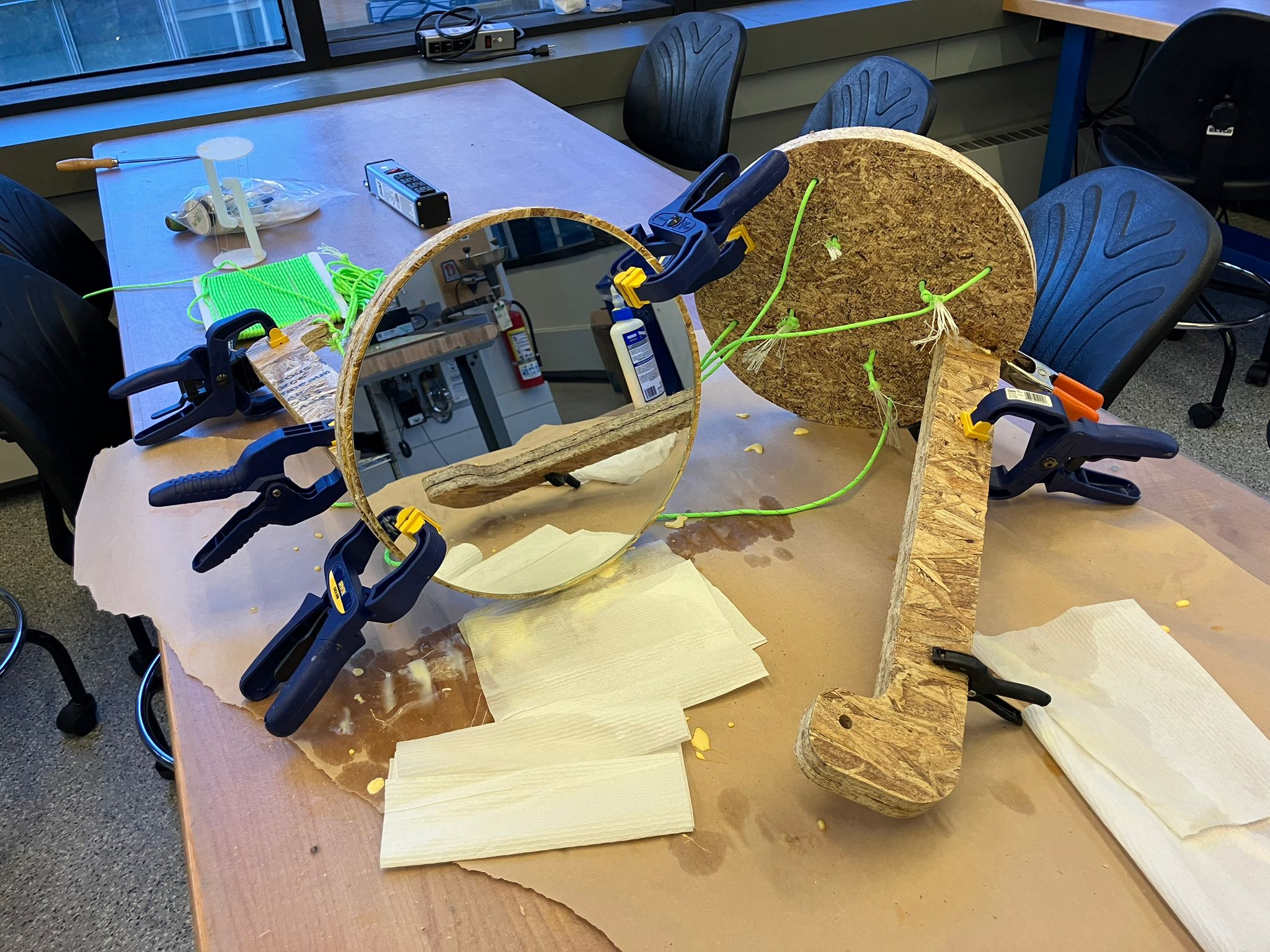
- For mirror attachment, apply appropriate adhesive (silicone glass adhesive recommended, though wood glue is acceptable) and secure with clamps
- Allow complete adhesive cure time before applying any stress to the joints to ensure maximum bond strength
Wood gluing mirror with clamps for secure bonding
Cured glue after 24-hour wait period
4. Tightening After Gluing
- Verify that paracord remains freely movable and is not bonded to the wood surfaces by adhesive
- If paracord is stuck, apply gentle pulling force or carefully use a utility knife to separate any adhesive bonds between paracord and wood surfaces
- Execute the tensioning procedure following the same methodology established in step 2, utilizing knots and zipties for secure fastening
- Apply tension to the paracord until achieving equilibrium where opposing forces are balanced
- Mark the optimal tension point using a permanent marker or ziptie for precise reference
- Create a secure knot at the marked position to maintain the desired tension
- Install zipties between the knot and hole to prevent slippage, continuing until the system reaches a stable, non-adjustable state
Horizontal mirror configuration after gluing
Horizontal mirror side view showing stability
Ziptie tightening for final tension adjustment
Final tight mirror configuration
Final tight assembly with mirror properly mounted
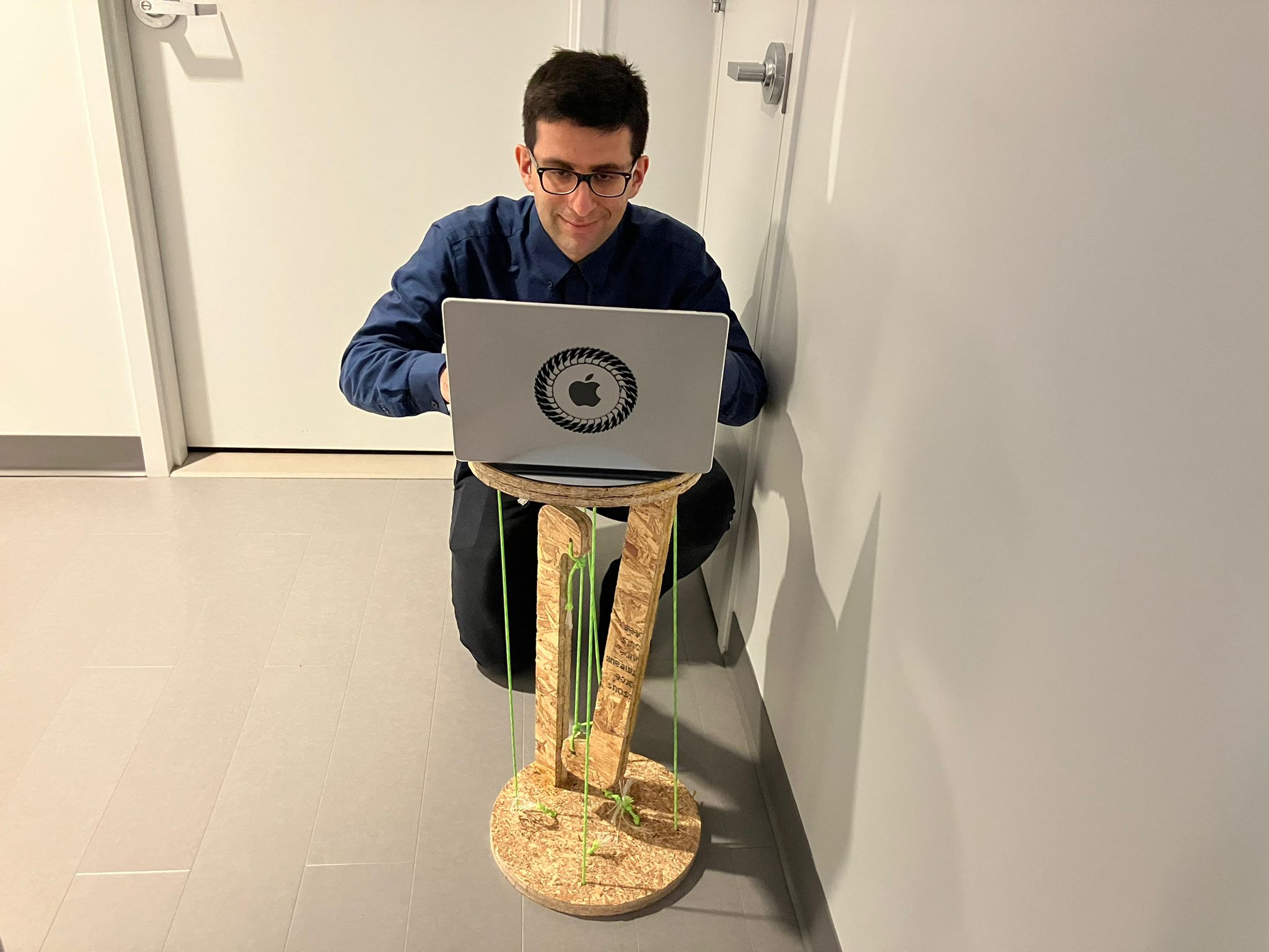
5. Final Assembly
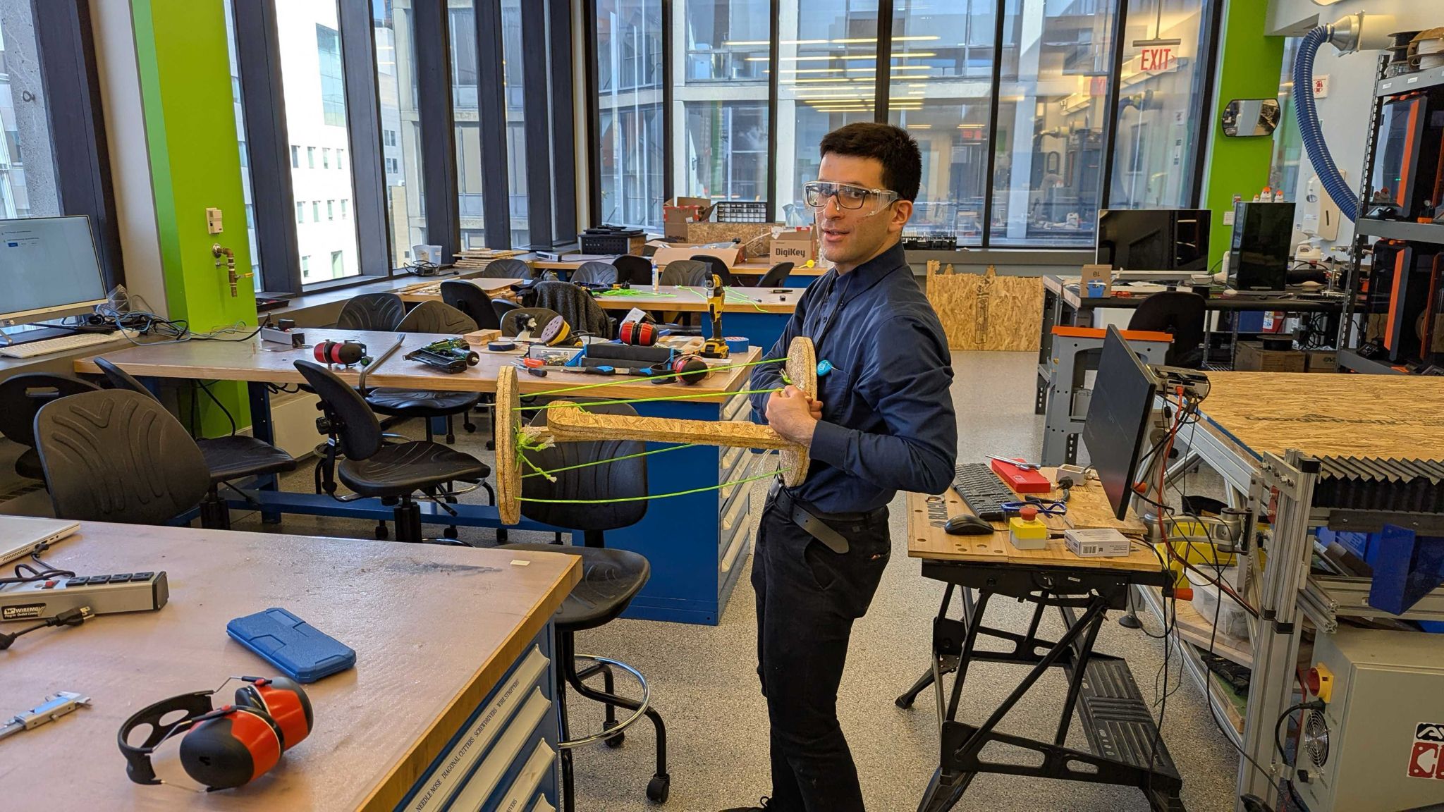
- Complete the final assembly process and conduct comprehensive stability testing to verify structural integrity
- Perform load testing with various weights (monitor, laptop, iPad) to validate the assembly's load-bearing capacity and safety margins
- Verify horizontal stability and confirm the levitation effect is functioning correctly under different load conditions
- Trim excess ziptie material flush with the assembly for a clean, professional finish
Final working stable assembly

Monitor weight test showing stability
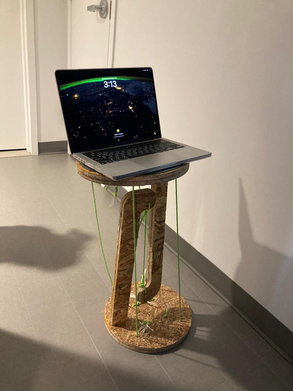
Laptop stability test demonstrating load capacity
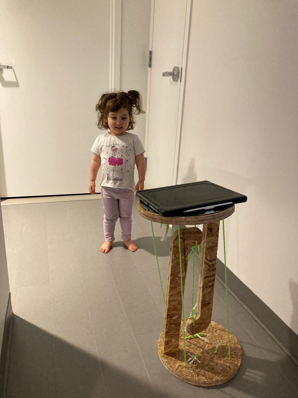
iPad stability test showing versatility

Baby for scale showing actual size
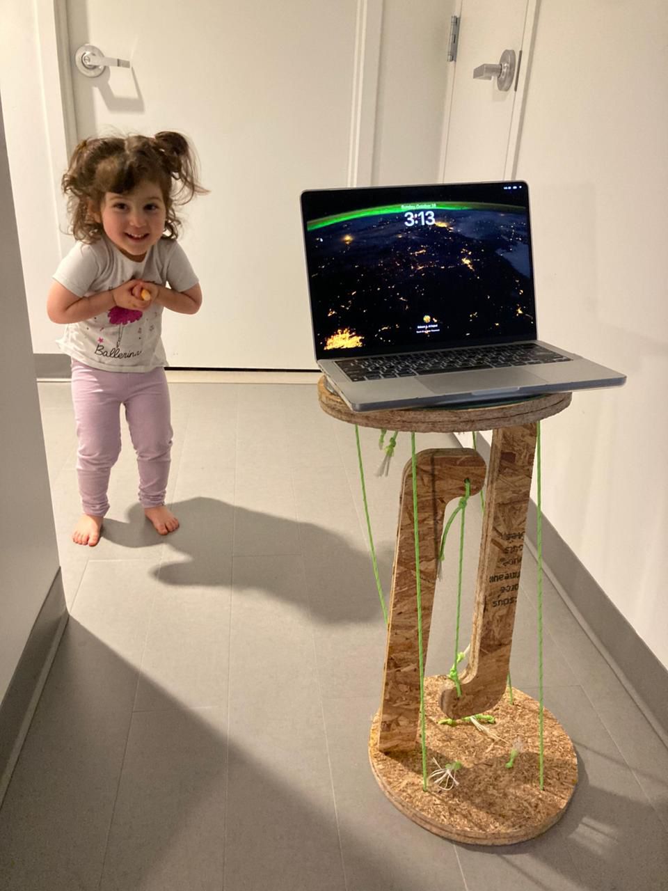
Baby happy with the floating mirror assembly
Final trimmed neat assembly ready for use
6. Scaling Up Design
Scaled to about 160cm in length, exactly double the current arrangement! The plan is to machine this scaled up version after class because of the limited wood stock in the class.
Scaling Design Steps (Estimated Time: 30-50 minutes)
- Apply non-uniform scaling to all components using modify → scale → non-uniform, maintaining original thickness (circles: scale x,y axes only; legs: scale x,z axes only)
- Reposition plate components along the z-axis, then align leg components with their corresponding mounting holes
- Remove existing joint holes and dogbone features from the design timeline to prepare for recreation
- Recreate extrusion cuts and apply dogbone modifications to the new scaled geometry
- Return to CAM workflow using the same procedures outlined in Anthony's CAM Tutorial
Design scale-up timeline showing the scaling process in Fusion 360
Future Parametric Design
In the future, will create parametric design by defining the lengths in terms of other lengths and then can scale by setting values to the base parameters of the design.
Design Files
Complete design files, CAD models, and manufacturing files for the floating mirror tensegrity project.
CAD Design Files
Complete Fusion 360 design files and manufacturing models for the floating mirror tensegrity structure.
Fusion 360 Project
HTMA Team Link: Floating Mirror v12.3mf Project
Download Links
3MF Model: Complete 3D model for 3D printing and visualization.
DXF File: 2D drawing file for CNC machining and laser cutting.
Flat 3MF: Flat configuration for 3D printing assembly testing.
Manufacturing Files
G-Code: For our shop's printer for flat configuration (0.4mm nozzle, 0.2mm layer height, PLA, 1h52m print time).
TAP File: For our shop's CNC router (postprocessed numerical control file).
Group Assignment Demo Tabs for CNC Router Characterization
Design files for the CNC router characterization test parts used in the group assignment to determine design rules and manufacturing parameters.
Demo Tabs Design
Demo Tabs v8.f3d: Complete Fusion 360 design file for CNC router characterization test parts with various joint clearances (1.995", 2.000", 2.005") and tab configurations for testing runout, alignment, and fixturing parameters.
Reflections & Learnings
Key insights and lessons learned from this week's computer-controlled machining work.
Key Points
- Proper CAM workflow and toolpath optimization are critical for successful CNC machining
- Tab placement and removal strategy directly impacts part quality and post-processing time
- Subtractive manufacturing offers precision and material properties not achievable with additive methods
- Design must account for tool geometry, cutting forces, and material removal strategies
- Understanding the relationship between design intent and manufacturability prevents costly mistakes
Machining Process Insights
- Understanding the importance of proper CAM workflow and toolpath optimization
- Learning the critical role of tab placement and removal in CNC machining
- Appreciating the precision and capabilities of subtractive manufacturing
- Understanding the relationship between design and manufacturability
Contributions
Acknowledgements for help received during this week's computer-controlled machining work.
Course Staff & Instructors
- Alfonso — Comprehensive recitation on subtractive processes and CAM workflows
- Dan — Advanced techniques and optimization strategies
- Anthony — CAM tutorial and workflow guidance
Ethical AI Use
Transparent documentation of AI assistance used in this week's computer-controlled machining work.
📋 General Guidelines: See General Commands for Cursor on the homepage for standard guidelines and commands used consistently throughout documentation development.
AI-Assisted Week 6 Documentation
This week's documentation was significantly enhanced by Cursor AI to transform project notes into comprehensive professional documentation. The AI assisted with creating structured sections for recitation notes, design inspiration resources, CAD process documentation, CAM workflow details, and complete design files organization with proper linking and technical descriptions.
AI-Assisted Individual Assignment Documentation
The individual assignment section was significantly enhanced by Cursor AI to transform project notes into comprehensive professional documentation. The AI assisted with creating structured subsections for OSB assembly processes, organizing step-by-step procedures, integrating media files, and developing professional technical descriptions for all assembly stages.
AI-Assisted CNC Router Design Rules Documentation
The EECS Shop CNC Router Design Rules section was enhanced by Cursor AI to transform characterization notes into comprehensive professional documentation. The AI assisted with creating structured sections for runout and clearance measurements, formatting measurement tables, organizing design rules, and integrating download links for data files.
 This work is licensed under a
Creative Commons Attribution-NonCommercial-ShareAlike 4.0 International License
This work is licensed under a
Creative Commons Attribution-NonCommercial-ShareAlike 4.0 International License