final project: pulse-responsive lightsaber
final project time is upon us! and there are many, many things to do. i'm sticking with an idea that's very close to what i proposed at the beginning of the semester--i'm still building the lightsaber. i've decided to spice it up a little bit by making it pulse-responsive (the blade will change brightness in time with the user's heartbeat... sort of, but that's a story for a bit later), but other than that the idea is the same.
since the last time i updated on this, many, many implementation details have changed. i'll outline everything below, but just know that not everything is exactly the same as it was. (as if a project could ever be that well-planned.)
electronics
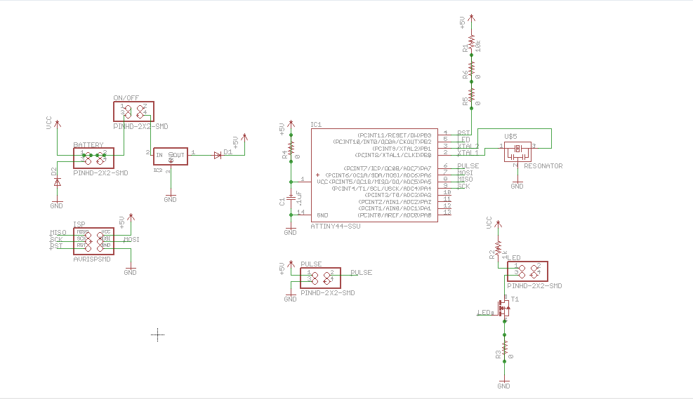
the board is simple: take input from a pulse sensor (more on that later) and use that input to drive variable current to an LED. the attiny44 and i are becoming very close friends. though i needed a small chip, i went with the 44 over the 45 because the 44 has two dedicated PWM pins. given the time constrainsts on this project, hardware PWM seemed like a much better option than trying to implement the same functionality in software; i've also had some pretty miserable experiences trying to help other classmates debug their 45 circuits during previous weeks, so i'm a little put off by the chip.
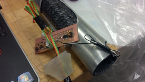
regardless. there were two somewhat difficult parts of the basic electronics design. first, it was hard to get the interface to the input/output components right. i'm housing the electronics in the handle, but the pulse sensor and LED both need to have some distance from the board to fit properly. so i needed some sort of flexible cabling. i settled on adding a large number of 2x2 male headers to the board, then use ribbon cable with a female header to attach to the sensor/LED and allow for the most flexibility.
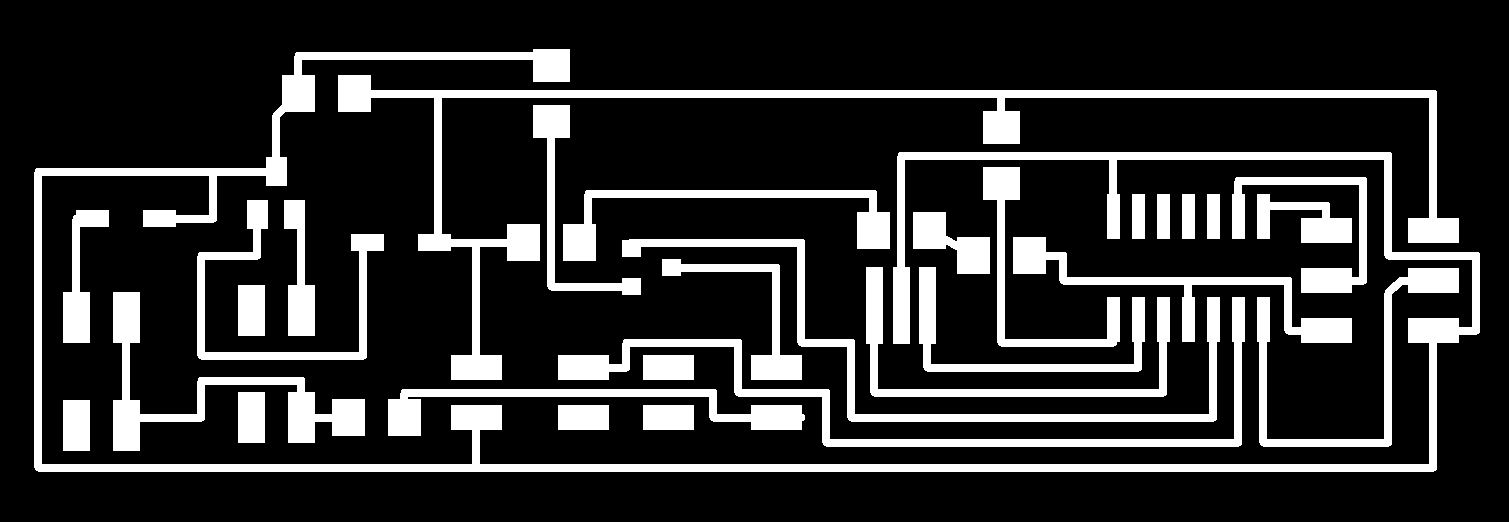
the second tough thing was laying out the traces so that the board was slim enough to fit inside the saber handle. i'm only working with a 1.5" diameter; to be on the safe side, i wanted to keep the board under 1.25" wide. routing the traces took AGES. eagle's autoroute feature was (predictably) unhelpful, so i ended up relying quite a bit on 0-ohm resistor jumpers to make a one-sided board work. i didn't really want to risk a two-sided board; given all the trouble i've had cutting out boards in the past (happened again, whee!), i thought going for a two-sided board might be a bit much.
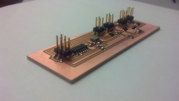
but after many hours of work, i finally milled and stuffed a successful board! i don't have the pulse sensor as of this writing so i can't test that, but i tested interface with the LED and it works marvellously. i'm a little worried about making sure the on/off button will work properly (i may have done a stupid thing), but i think it should be okay. sexy board pics below (and eagle design files linked all the way at the bottom):
electronics ii: pulse sensing
there are TONS of diy pulse sensors out there. they're mostly based on a concept called photoplethysmography (PPG), which is neat but slightly hairy to implement. the idea behind PPG is this: capillary tissues (like fingertips and ear lobes) contain a highly variable volume of blood that flucuates with every heartbeat. this is detectable with simple light sensing--if the tissue is full of blood, it reflects light differently than if it's empty of blood. if you point an IR sensor through a finger (or earlobe) towards an IR-tuned photosensor on the other side, you can actually pick up those differences in blood volume optically and track heartbeat.
well, theoretically, anyway. the best-looking sensor i found was this guy--they're totally open-source and so have schematics online. making the board myself would require a lot of parts sourcing, since most components i would need weren't stocked in the fab lab; i thought i might try to go really simple and use the "hello light" board neil designed for input devices week. the phototransistor used has a peak sensitivity in the IR range, and the lab keeps IR LEDs in stock. in theory, this board should have worked. in practice, it turns out that the phototransistor is meant more for switching applications and so tends to swing between two more "digital" states rather than having true analog behaviour, which is exactly the opposite of what i needed for the pulse sensor. because i was running low on time, i decided to just purchase the pulse sensor from sparkfun, but it was cool to work with the phototransistor even though it didn't quite behave like i wanted. maybe i'll try again someday, with more well-tuned parts. i would include a video of the failed attempt, except i connected the power backwards while attempting to take the video and exploded the voltage regulator, which i had no time to fix. alas. this is why we use diode protection!
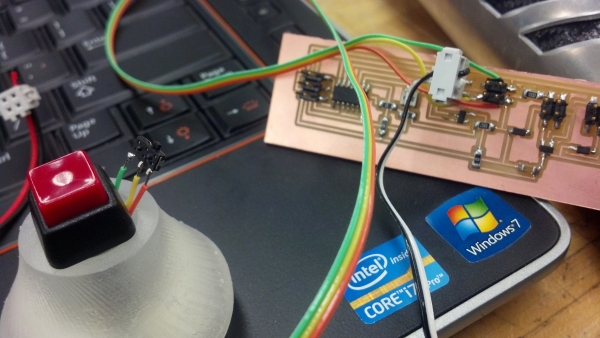
the pulse sensor i bought worked beautifully for about a week, then crapped out. i'm not sure if the sensor or the connections are the issue; i'll look into it when i have more time. instead, i just decided to fake it: instead of the sensor, i connected a little slide switch to the circuit. push it one way (and connect the input pin on the attiny to ground) and the saber flashes in a pretend heartbeat pattern; push it the other way (input pin to 5V) and the blade is stably on. since the switch was surface-mount, it was small enough to bind to the side of the power button with some electrical tape. it's barely noticeable, which is nice, and i like that the saber has multiple modes now. code at the end.
handle design
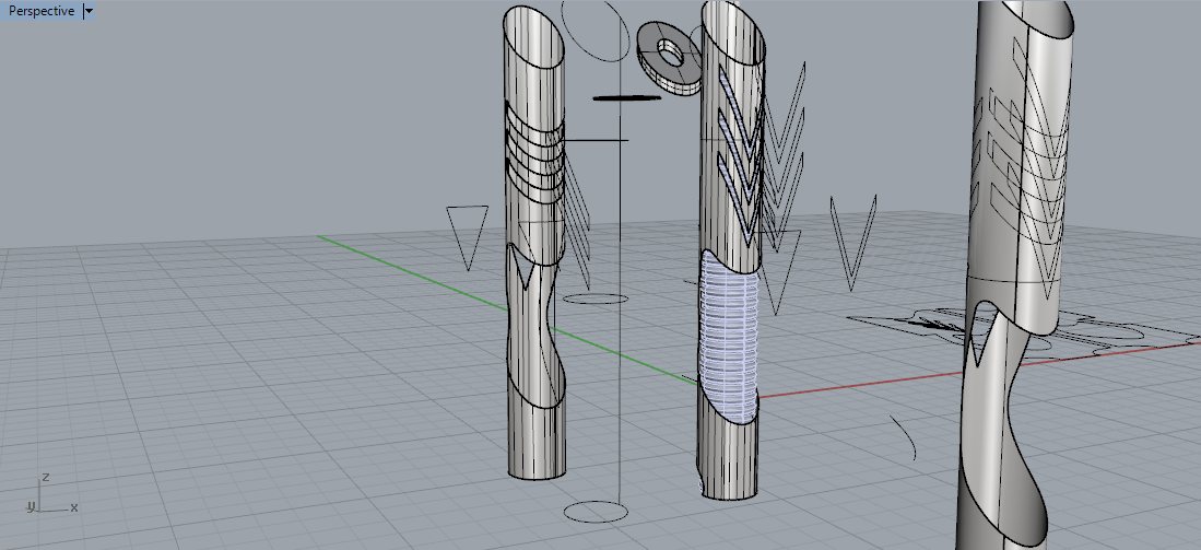
i'm sticking with the carbon fibre/aluminium vibe that i started off with. i already have the carbon fibre tube from week 8, so all that's left to do is make the aluminium sheath to go over it. thank god for james (again, for the millionth time), who walked me through designing it in rhino. it looks spacey and futuristic and badass, if i do say so myself:
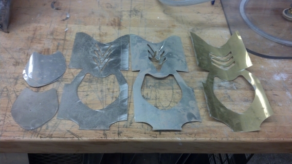
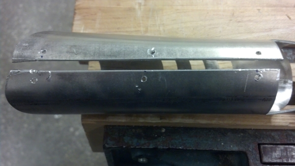
to realise the design, we waterjet some 2024 aluminum scrap and stuck it in the metal roller. speaking of the metal roller, i had a delightfully successful prototype, and then many interesting waterjet attempts (thinner metal than the 2024 failed miserably):
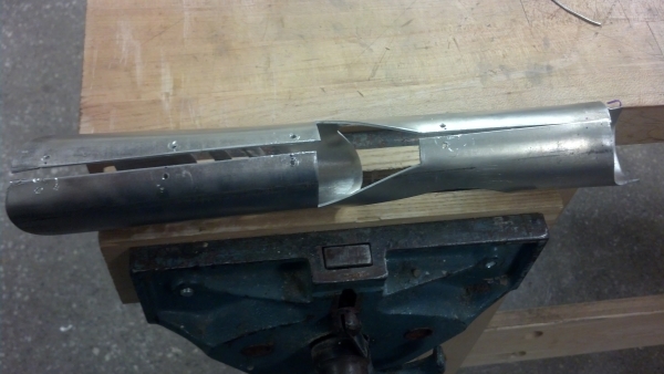
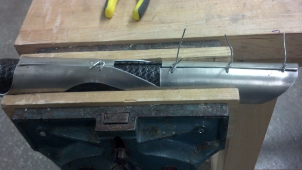
one would think that such a successful prototype would lead to a successful end product. one would be wrong. something about the cuts in the metal made it absurdly hard to roll it once it was cut, so after about an hour of fighting with it i was left with some gaps along the seam. the best solution i could think of was to bind these with wire; i hammered on it with a rubber mallet (as did james) for quite some time and it didn't make much of a difference. but the wires aren't a terrible solution for now.
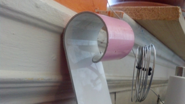
i also needed a good way to connect the blade (more soon!) to the handle. james suggested neoprene sleeving; i ordered some from mcmaster-carr but it was significantly less pliable than expected and i couldn't use it. so i went to home depot and got this guy:
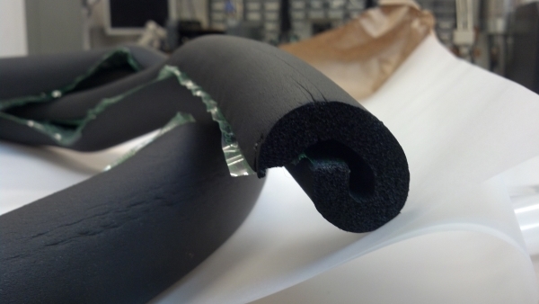
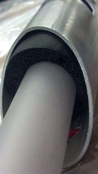
and it worked PERFECTLY. it took a bit of finagling and brute force to get it into the carbon fiber part of the handle, but once it was in (held with double-stick tape, no less) it held the blade very steady. i'm extremely pleased with it. plus, it looks pretty nice:
blade design
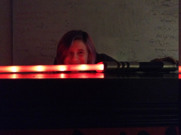
during output devices week, i toyed a bit with the idea of making the blade out of an LED ladder. given the trouble i had with current drive last time, i rethought that idea... and then rethought it again. i wanted to go for one super-bright LED in the hilt, use a parabolic reflector to get the light at the right angle to get good internal reflection, and sanblast the inside of a polycarbonate tube to get the most light reflection possible all the way down the blade. however, none of that worked. the LED was INSANELY bright, but didn't diffuse well through the tube; i had to sandblast the outside (the sanblast chamber was too small for me to get the hose pointed down the tube), but even with matte film on the inside of the tube the light didn't diffuse well. it flared up at the base and came out the end, kind of like a laser but much less bright. given the limited amount of time i had left, i decided to go with the easier but less beautiful LED ladder alternative. and because of power issues, i didn't want to include more than 10 LEDs in the ladder, which results in this spotty effect:
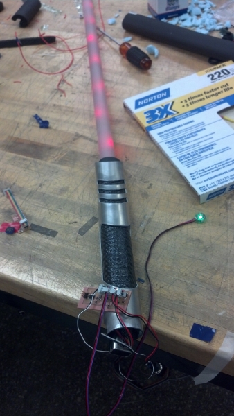
it's not the worst. it works, even though i'm driving .6W of power through what i assume is a .25W resistor (oops). i will also insist on using red light, even though green is (optically) the right choice (our eyes are most sensitive to it, so green appears brightest even when dissipating the same amount of power). putting some matte film in the blade helped diffuse the light a little bit, but in future iterations of this design i think i'll want to use something like this blade film from "the custom saber shop." alas, no time to order any for this project. IAP project, though. it'll be wonderful.
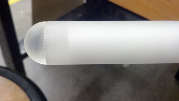
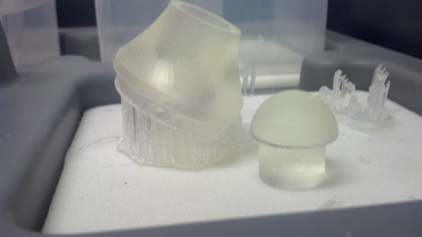
finishing touches
i 3D printed some end caps for the hilt and the blade tip on the form1 (since it can print clear/opaque material). i tidied up some wires, integrated the button into the base of the hilt, and plugged everything together. and it is lovely. i'm really pleased with the final result. all the design files and schematics are below (just be aware that i designed the schematic for pulse sensing, and haven't remade it for my hacked pulse, so the code and schematic don't match up perfectly).
design files
SolidWorks & Rhino files
eagle schematic and board files
arduino code