Week 10: Output Devices
Introduction
This week we continued our focus on electronics by working with output devices. This week was a bit strange for me for a variety of reasons. The idea this week is to control some output device with the microcontroller, but for my final project (the bluetooth boombox) I will be driving the speaker with audio from the bluetooth module and really only driving the logic from the microcontroller. Instead I decided to see if I could control the volume of the speaker from the microcontroller, again something that's probably better done via the bluetooth module anyways. All in all the result is that I learned a ton and walked away with some important knowledge I will need to finish my final project, but ultimately failed to produce what I intended. Read on to find out more.
Testing
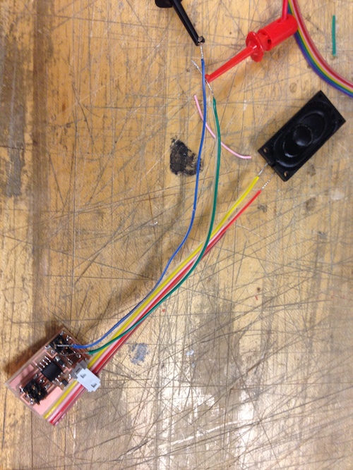
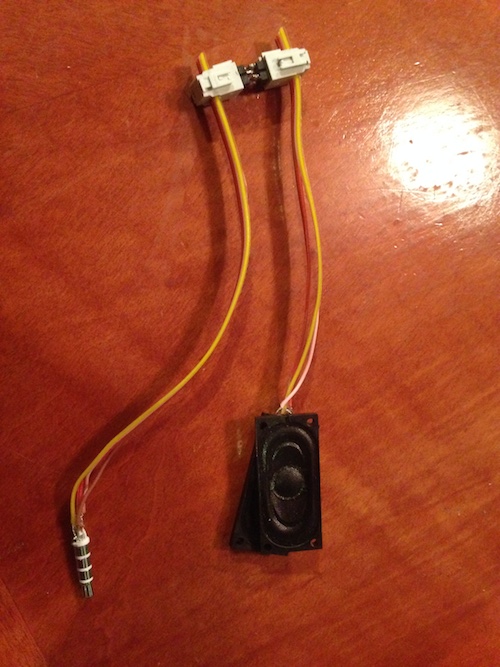
I started off by doing a couple of experiments to test the waters before I moved forward. I started by building the simple speaker example that Neil demo'd in class, just to get comfortable with the parts and in particular the response of the speaker to different voltages. I then did another experiment where I took apart a spare pair of earbuds to tap into the headphone jack. Little was I aware that Apple makes everything hard to take apart, apparently including its earbuds, so I couldn't simple cut the line and solder my own wires onto it. Eventually I just chipped away at the plastic and got direct access to the connector. I finally connected that up to a couple of speakers and used this rig to look at the voltage output levels from the iPhone as well as the variation over the software volume control on the phone. I used all of these numbers in my amplification calculations later on down the road.
Design
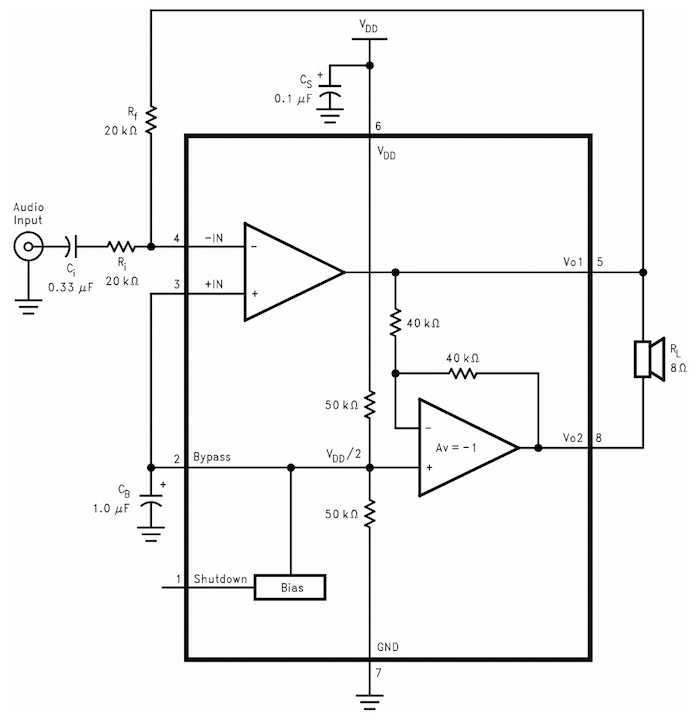
I did a lot of research about audio amplification and I found a whole world of science behind it. The biggest things I learned was that the best way to do software control of volume was to control the resistive divider input to an amplifier. Ideally I would use a logarithmic potentiometer instead of a linear one because the human ear responds in a logarithmic fashion to sound (something I confirmed looking at the change in voltage on the iPhone output). Unfortunately I was a big overwhelmed by the options out there and didn't get to order a log-pot or amplifier in time but I did find the LM4861 in the lab and decided to use that. I went with the suggested application circuit and used the equations provided in the datasheet along with my measured values to calculate the values for the resistive divider.
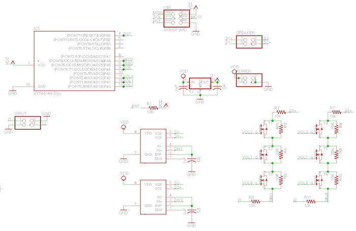
In order to make up for not having a digital potentiometer I decided to create one using 3 transistors and 3 resistors of different values. The idea is that the microcontroller could short across a resistor (essentially removing it from the circuit) and thus changing the resistive value of the network.
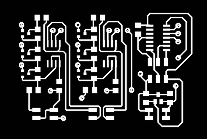
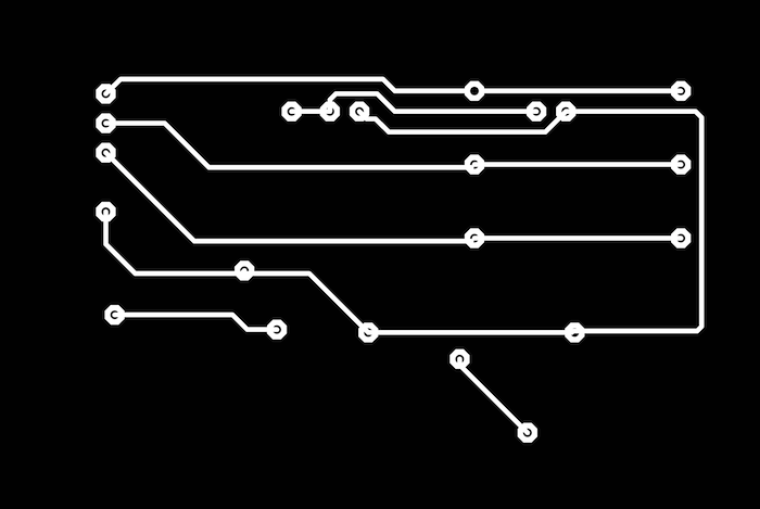
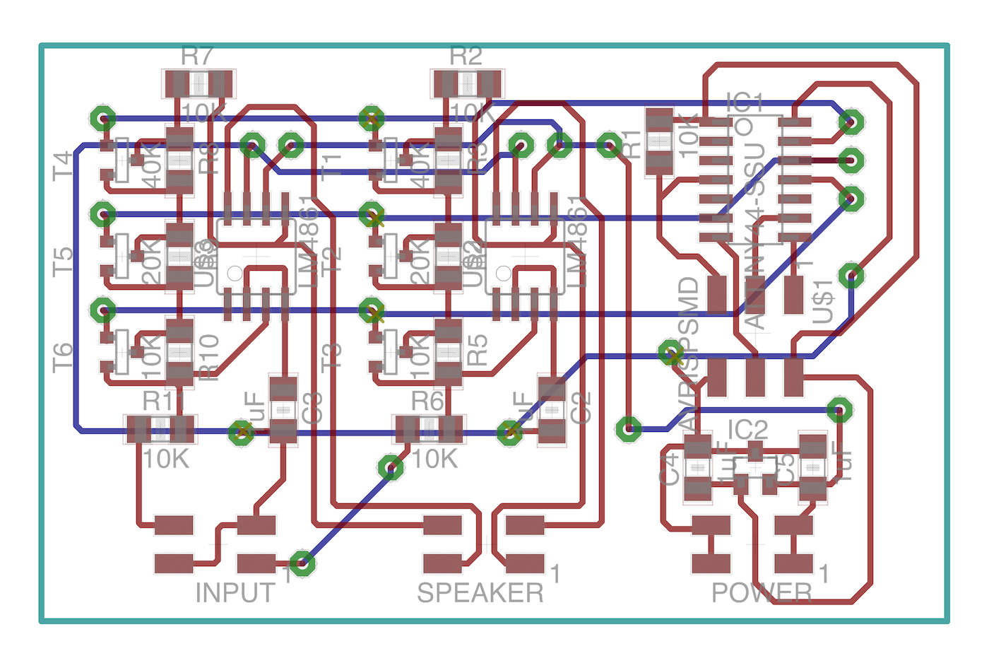
This circuit was quite interesting to layout and the fact that I needed two (both left and right speakers) meant that I had to create my first double sided board. In eagle this was a pretty simple affair, simply dropping vias that use the tool diameter of 1/32". I exported the top and bottom traces as seperate images. Then I exported the vias layer and used GIMP and a bucket fill to color the entire background the same as the via color, leaving me with just the image of the holes. Finally I added some circles to the corners of the outline image so that I could properly realign the board after milling the top and before milling the bottom.


You can download all of the files I used to design the board below.
Download Eagle Design Files
Production
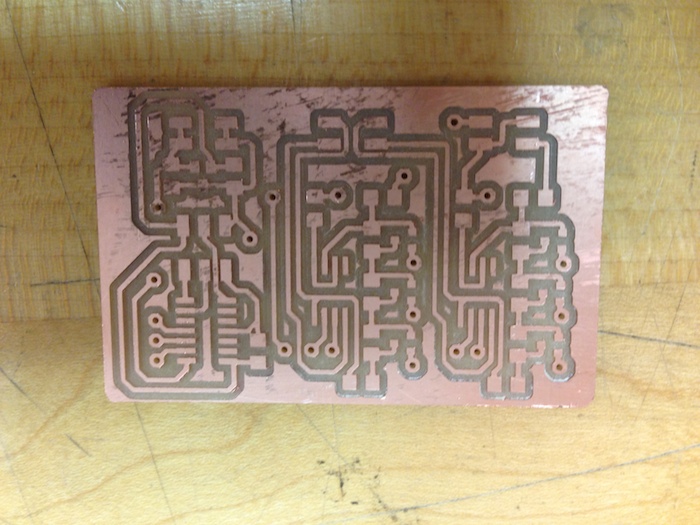
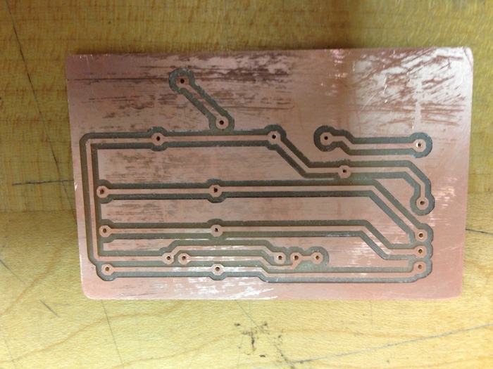
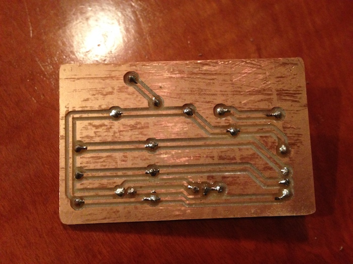
It was then time to actually produce the board. I followed the same steps most people did when making two sided boards, first milling the top traces. I then milled just the holes and then the outline layer. Once the outline was complete I removed the board and shifted it to align it with the edges created in the piece it was cut from. Finally I milled the bottom traces after offsetting the x and y by the tool diameter (.79mm). I filled in the vias by threading wire through the holes and soldering on both ends.
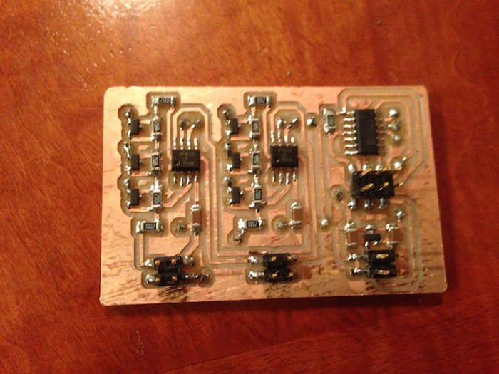
Once the board was all connected I hooked it up and programmed it with a script to toggle the pins hooked up the to transistor-resistor network. That network did work and the resistance values changed as expected. Unfortunately the amplifier did not work, something was configured incorrectly which led to the output being a constant dc high voltage. This would suggest to me that the gain was too high but my calculations using the datasheet indicated that was not the case. I ran out of time and could not figure out how to make the amplifier work but I still learned some valuable lessons for my final project. Most importantly I learned how to make a double sided board, but I also learned a little more about the electronics of speakers which has convinced me to use more of the software volume control systems available to me because they more reliably handle the logarithmic growth needed. The one component I will still need to figure out is the amplifier, because I will almost certainly need to use one to power a speaker with any sort of appreciable volume.