Week 5: Electronics Design
Introduction
As with electronics weeks, this week was a little more of a straightforward assignment. Last time we were given an electronics task we were given the files representing the board layouts and told to simply produce and stuff them. This week we took the task one step further by actually designing the layout of the board and adding some components of our own. Two weeks from now we will actually go about programming these boards.
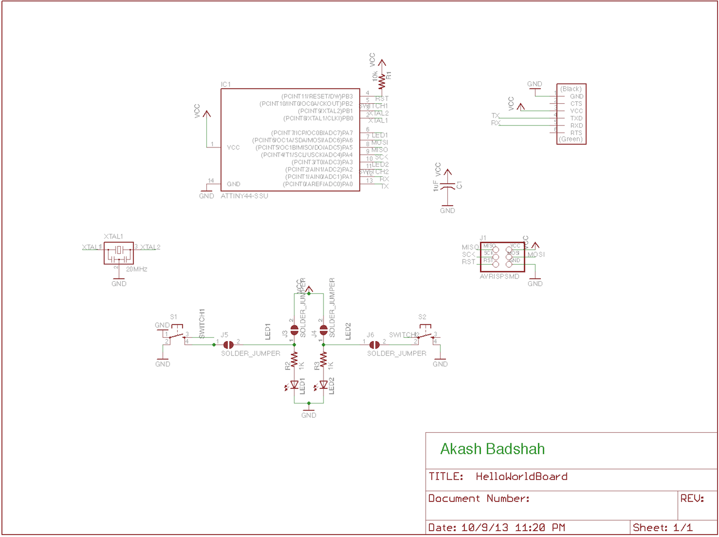
We were asked to take the Echo Hello-world Board and redesign it with out own layout. In addition we were required at minimum to add one button and one LED. Knowing that there were a total of 4 digital I/O ports left available on the ATTiny44 I decided to add 2 buttons and 2 LEDs to take full advantage of the capabilities.
Also, knowing that we wouldn't program the boards until Week 7, I also wanted to add a hardwired circuit for the LEDs and buttons that would allow them to function in a sort of "offline" mode. Specifically I added jumpers which, when connected, would leave the LEDs always on and the button presses would turn them off. Disconnecting the jumpers would allow the LEDs to act as programmable output and the buttons as programmable input.
Eventually I would like the board to be a sort of crude drum pad, where you can initiate the board to record, then press the buttons to fire the LEDs, end recording, and finally loop the pattern you have recorded. In some ways, the offline mode would be the same function, you just wouldn't be able to save the pattern.
Design
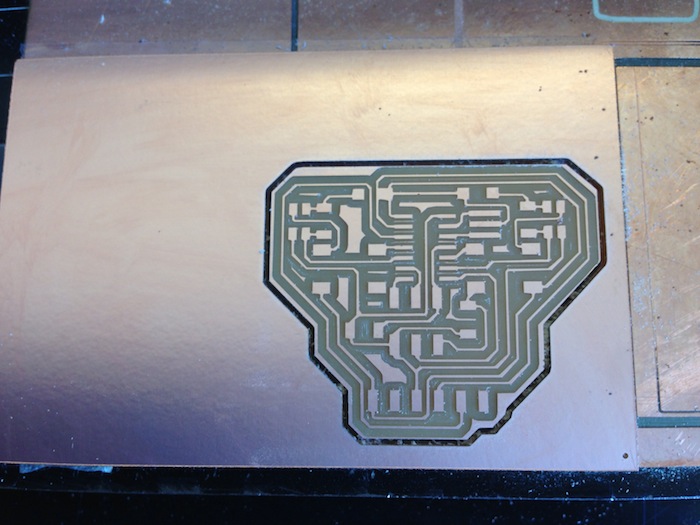
I used Eagle to deisgn the board layouts. I've used both Eagle and Altium in the past and while I find that Altium is a little more powerful and fully featured, Eagle is more thansufficient for the layouts we are doing in this class, especially because they are single layer. I had particular difficulty in laying out the board in a single layer because of the circuits introduced by the jumper system. In overcoming this I took particular advantage of the fact that most of my parts could have traces run underneath them, so I managed to get away with needing no extra 0-ohm resistors.
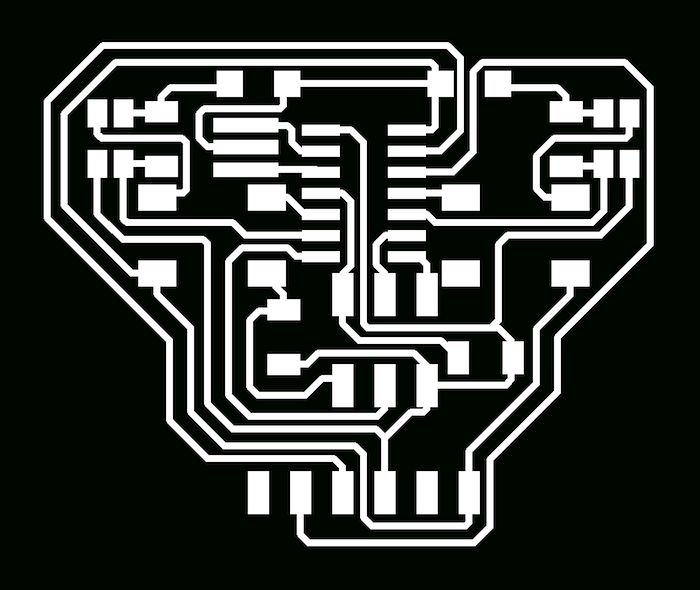

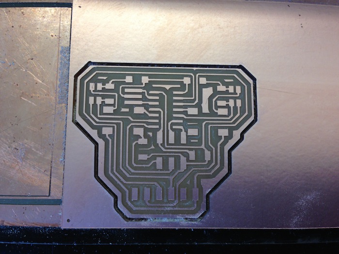
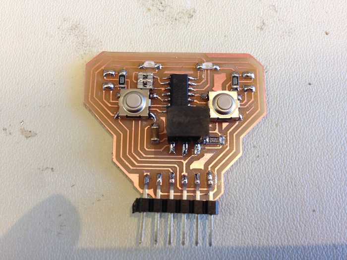
I also thought it would be kind of cool to have the board look like a skull, so I symettrically laid out the components in that shape.
Download Files
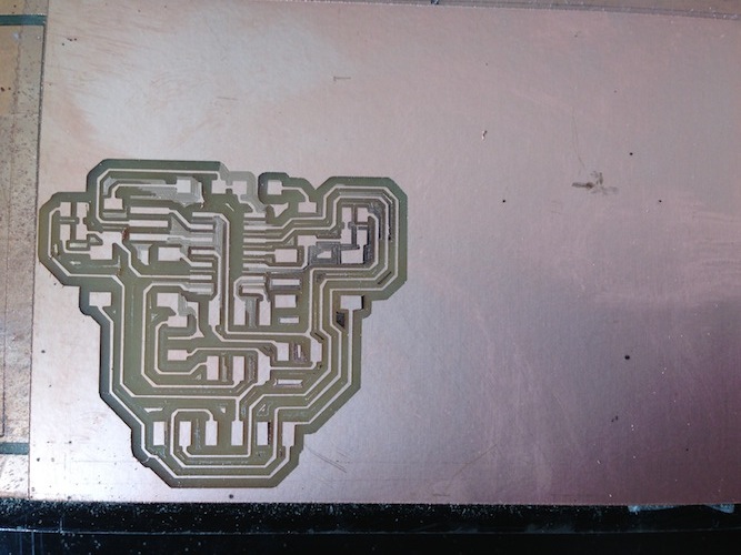
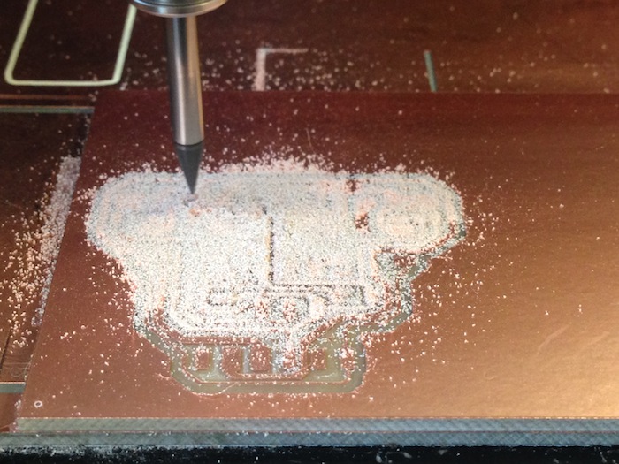
Production
In my first iteration of the baord I messed up the jumper circuit itself and accidentally shorted GND and VCC, I realized this quickly after milling the traces and fixed the design.
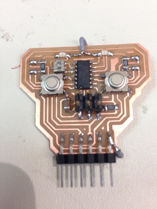
In the second iteration, I realized I left two grounds seperated from one another, so I needed to add a wire to connect them. After adding that wire it was functional.
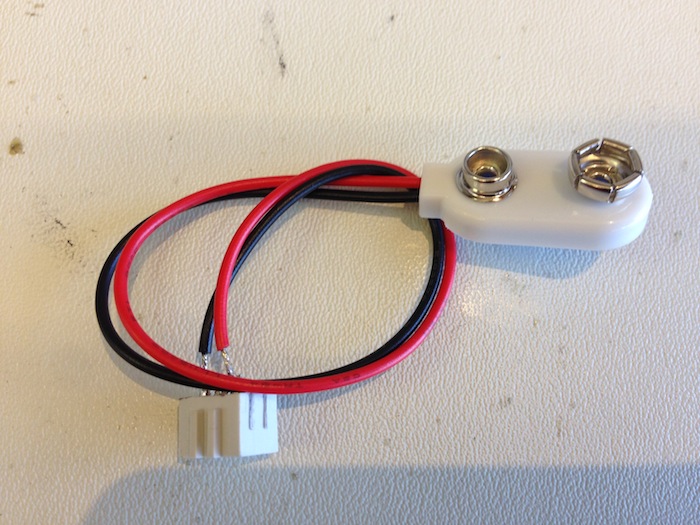
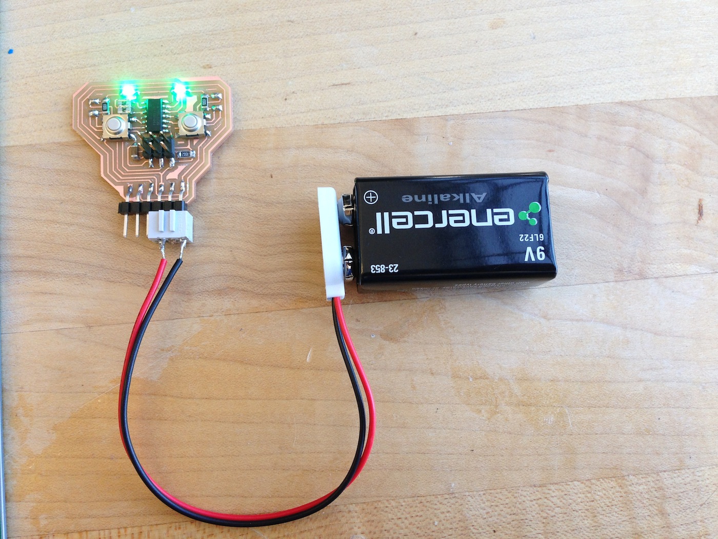
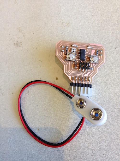
I finally did one more pass after connecting those two grounds in the design, and I also created a connector for a 9V battery so the device could be used portable (while walking to and from class for example).
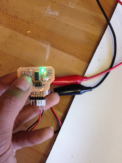
The board works great and I'm looking forward to programming it and giving it some memory!