Week 9: Input Devices
Introduction
This week we learned more about electronics, and the goal was to learn about input devices (and by extension the ADC). I also used this opportunity to make some progress on my final project, building a first pass at the input device I'll use in my speaker system, a volume touch bar.
Design
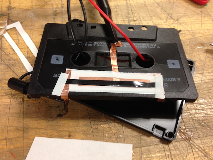
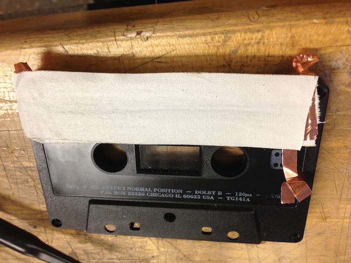
I started out with an idea for a resistive touchpad that a person could slide their finger across and it would change resistances just like a linear potentiometer. Essentially I wanted to make something like the SoftPot Potentiometer. I found a couple of diy projects online that made them by suspending video tape over a conductor and using the tape as the variable resistor. I decided to follow this tutorial so I started by acquiring some cassette tapes. I managed to get a prototype working but it was not a great range and quite noisy. I think I could have gotten better results had I used a wider video tape instead of cassette tape, but I decided to change from the resistive route entirely at Neil's suggestion.
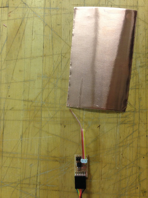
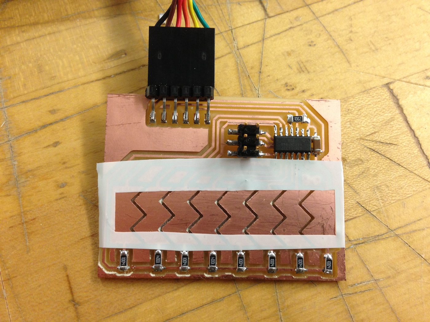
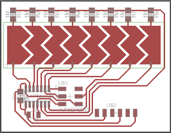
I started by building the simple step response sensor described by Neil in class, to get a feel for using capacitance. I then decided to create a linear sensor with 8 capacitive nodes, borrowing some of the ideas and code from Matt Blackshaw's previous project. I decided to put my nodes in a chevron shape so that there would be some overlap between the nodes that were excited. Using this I could compute the touch location as the centroid and have a full analog slider instead of a discrete one.
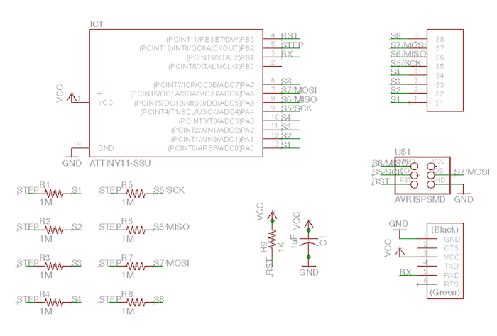
Feel free to download the eagle design files from below and make one of your own.
Download Eagle Files
Fabrication
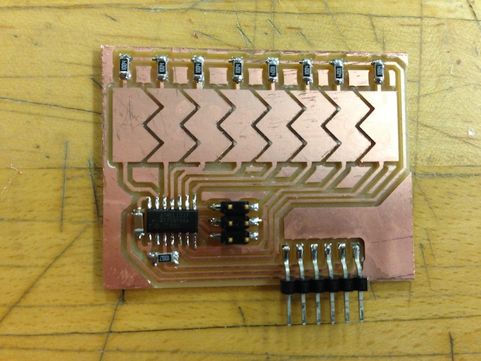
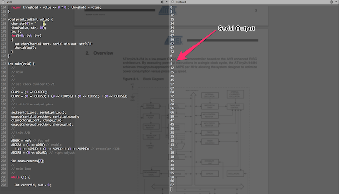
I then went about milling the actual board. I think the set screws in the modela might be stripped because the endmill kept lurching downward. It didn't affect the quality of the board, it just meant all the cuts were a lot deeper, which produced a pretty interesting effect. After stuffing the board it was on to programing it, which was pretty easy when running from Matt's old code (both were basically sensing 8 capacitive nodes). I also added code to change the serial output and to compute the centroid, so the output is a number between 0-80 representing the position of the finger along the slider.
Feel free to download the code to run this slider program from above. You then run the following commands to program the board and to run the serial program (if you have a mac)
  make -f Makefile
  sudo make -f Makefile program-fuses
  sudo make -f Makefile program
  screen /dev/[You're USB Port Name Here] 9600
Download Code Files
Overall the slider works really well and I'm excited to use it in my final project. It'll be interesting trying to expose just the slider part on the outside of the boombox case, I'll probably use the fvinyl cutter and stick the sensor copper right on the outside.