
This lesson was pretty straightforward: we had to reverse-engineer a circuit, the “Echo Hello World” board.
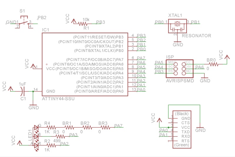
Using Eagle, I traced the nets from the board image and created my own circuit, adding a push button and RGB LED as shown below:
Next step was to make the layout. I have some tips here:
- Try to connect component pins on the side closest to the micro-controller.
- That means place the components adjacent to the pins on the micro-controller that the component uses.
- Change grid settings in Eagle. Mine were too sparse, so I couldn’t run wires appropriately. A good rule of thumb is to use the endmill size as your grid step.
- Run traces underneath components to maximize space
- Use the angled-wire tool when possible

I got really sick of running wires on the layout tool in eagle, so I decided to have some fun by putting in my own design patterns, as well.
I sent that black and white PNG to the modela and here’s what came out:

Unfortunately, I broke my first one trying to plug in the FTDI, here’s what happened:
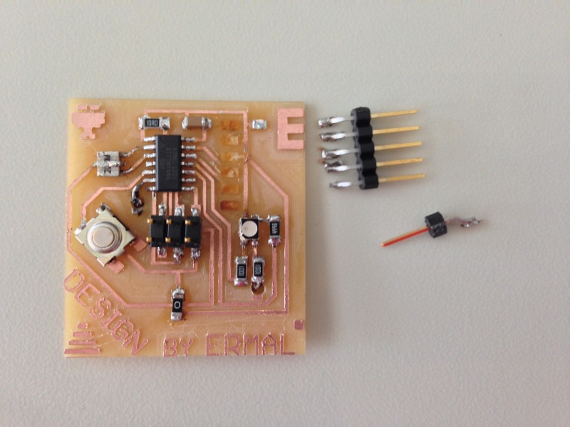 Luckily I made two. I used my programmer from a previous project, and after soldering the parts on again, I was able to program it by burning the arduino boot loader and voila!
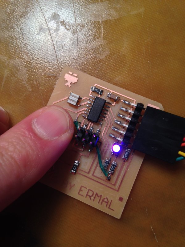
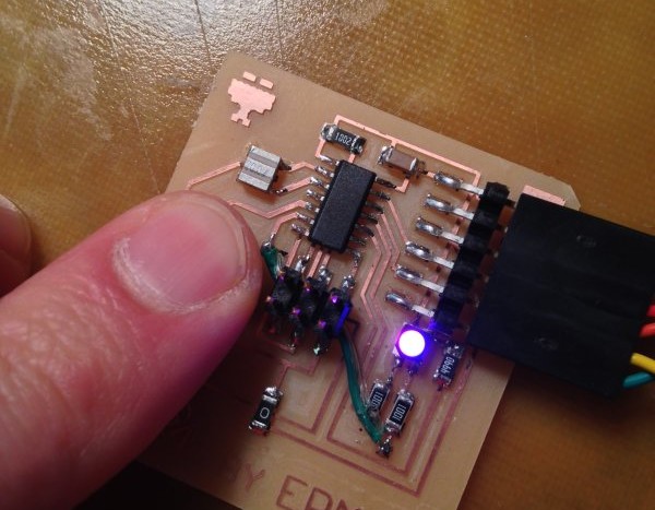
I made the LED fade from 1 to 255 in Arduino code when the user presses the button. When the user lets go, the LED dims back from the current value to 1. Couldn’t get the green channel to work, just red and blue for now. Will debug later to figure out what’s going on.
Tips on getting arduino to work:
- Download the hardware packages for ATTINY44 arduino bootloader here
- Use the “USBTinyISP” programmer in Arduino, if you are on Windows 7 or 8, download the drivers here
- For Windows 8, you will need to do an advanced startup and disable driver signing once just to install the drivers
- Select Arduino menu Tools -> Board -> ATTINY44 (external 20 MHz clock)
- Select Arduino menu Tools-> Programmer -> USBTinyISP
- Select Tools -> Burn Bootloader
- If you’ve got the right serial port selected under tools, you may now test your Arduino code.
- To enable pull-up resistors on pins, make sure in the setup() call of your Arduino sketch that you set the pin to HIGH using digitalWrite(), e.g.:
pinMode(buttonPin, INPUT);
digitalWrite(buttonPin, HIGH);