
Given that I’ve got some experience in embedded programming, I thought I would use this project as an opportunity to learn how to use something more high-level (Arduino).
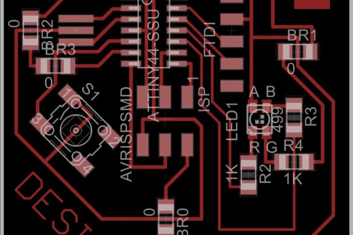
Previously, I designed a circuit with a push-button and an RGB LED, although I could only get 1 or 2 LEDs to light up. I thought maybe the problem was that the LED anode was incorrectly marked on the Eagle library module. To try and rectify this, I switched the green LED and anode pin on the design. Above is the revision 6 design of the circuit.
Still, no luck ![]()
I practiced my milling technique enough times, however, so now I’ve become really well-versed with the Modela. Anyway, here’s the code to fade:
// Ermal’s Button Code
const int buttonPin = 8; // the number of the pushbutton pin
const int redPin = 2; // the number of the LED pin
const int greenPin = 7;
const int bluePin = 3;
// variables will change:
int buttonState = 0; // variable for reading the pushbutton status
int counter = 0;
int reverse = false;
void setup() {
// initialize the LED pin as an output:
pinMode(redPin, OUTPUT);
pinMode(greenPin, OUTPUT);
pinMode(bluePin, OUTPUT);
// initialize the pushbutton pin as an input:
pinMode(buttonPin, INPUT);
digitalWrite(buttonPin, HIGH);
}
void loop(){
// read the state of the pushbutton value:
buttonState = digitalRead(buttonPin);
// check if the pushbutton is pressed.
// if it is, the buttonState is LOW:
if (buttonState == LOW) {
if(counter >= 255)
reverse = true;
else if(counter <= 1)
reverse = false;
// turn LED on:
counter = reverse ? counter-= 4 : counter+=8;
//fades only the green LED, while RED and BLUE are OFF
setColor(255,counter,255);
}
else {
// when button is off, it will fade back to the dimmest state without being off
counter = counter <= 1 ? 1 : counter – 4;
// turn LED off:
setColor(255,counter,255);
}
delay(16);
}
void setColor(int red, int green, int blue)
{
analogWrite(redPin, red);
analogWrite(greenPin, green);
analogWrite(bluePin, blue);
}
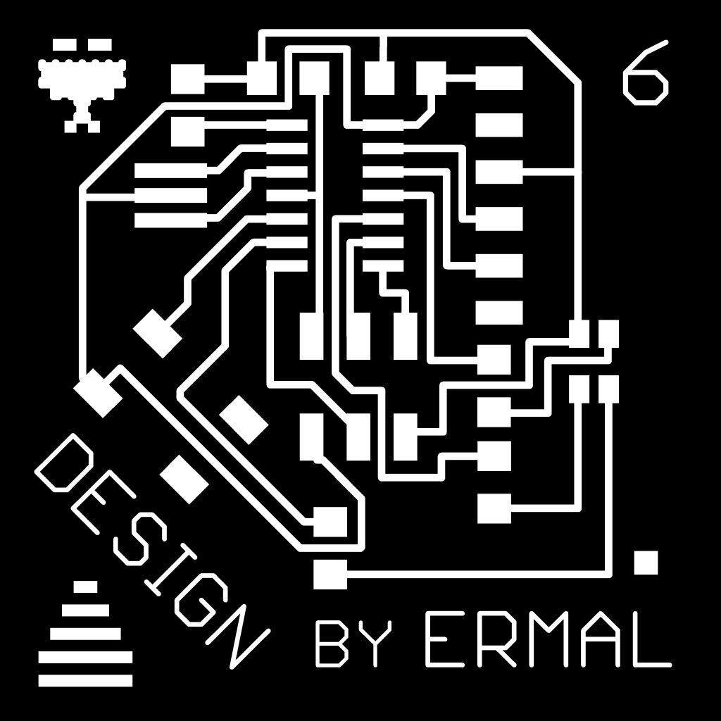
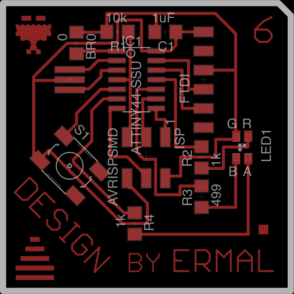
For reference, here’s the final board design
That’s it! Please refer to the previous circuit design for additional information and background on what this is and what it does.