Final Project
This page contains my final project outcome (for intermediate progress check out this page).Flower Wall
Introduction
My final project will be the design and production of an interactive office divider (on a small scale). I am hoping for a wall consisting of many small agents that can retract or expand making the wall more or less opague depending on light and/or the distance of people approaching, e.g. closing up for privacy if someone approaches quickly, or slowly opening in a friendly gesture if someone approaches in a normal pace.
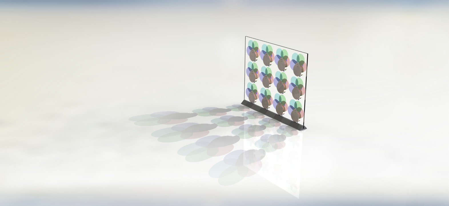
Picture rendered with Photoview 360 in Solidworks.
My research involves self-organizing systems, which is why I would like a wall of independent agents, individually simple, but collectively forming interesting patterns, inspired by natural systems such as flocks of starlings, or schools of fish.
Related Work
The idea of interactive walls is far from new. Actually, I think a couple of other people this semester are trying different versions of the same concept. Two of the labs which currently focus a lot of their energy on this area is that of Chuck Hoberman, who does the Adaptive Fritting Walls, and the Correll Lab which is working on the Self-Organizing Amorphous Facade. Chuck Hoberman does amazing expandable structures, however, in his wall all of the 'agents' are mechanically tied together to perform the same action. The Amorphous Facade from the Correll Lab have yet to publish material on any hardware prototypes beyond three modules.
Design Tools
I used Solidworks to make the model of how all the pieces would fit together, and to create the 3D printed shell which holds all the pieces in place; Eagle to design the circuit boards; Autocad to produce the DXF files for cutting the acryllic flower pedals and the acryllic wall; AVRstudio to program the processors in the agents; and Matlab to create a simulation tool to test different algorithms on.
Picture of a flower from Solidworks model.
Parts
Here is a list of all the parts I ordered for this project:
McMaster-carr:
1x 8702K619 Square nylon rod for the stand $30
1x
8589K83 2x2' 1/4" clear acrylic sheet for the wall $30
1x
85635K411 1x1' 3/32" red acrylic sheet $6.5
1x 85635K411 1x1' 3/32" blue acrylic sheet $6.5
1x 85635K411 1x1' 3/32" amber acrylic sheet $6.5
1x 85635K411 1x1' 3/32" green acrylic sheet $6.5
4PCB:
8 PCBs for $132
total
3Dprinted parts:
Generously
donated by the Wyss Institute for Biologically Inspired Engineering
I could have probably gotten all parts cheaper with more effort, but these are the vendors we normally order from in the lab, and so it was easy to add to the orders (+it saved on shipping).
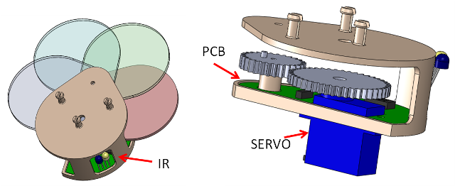
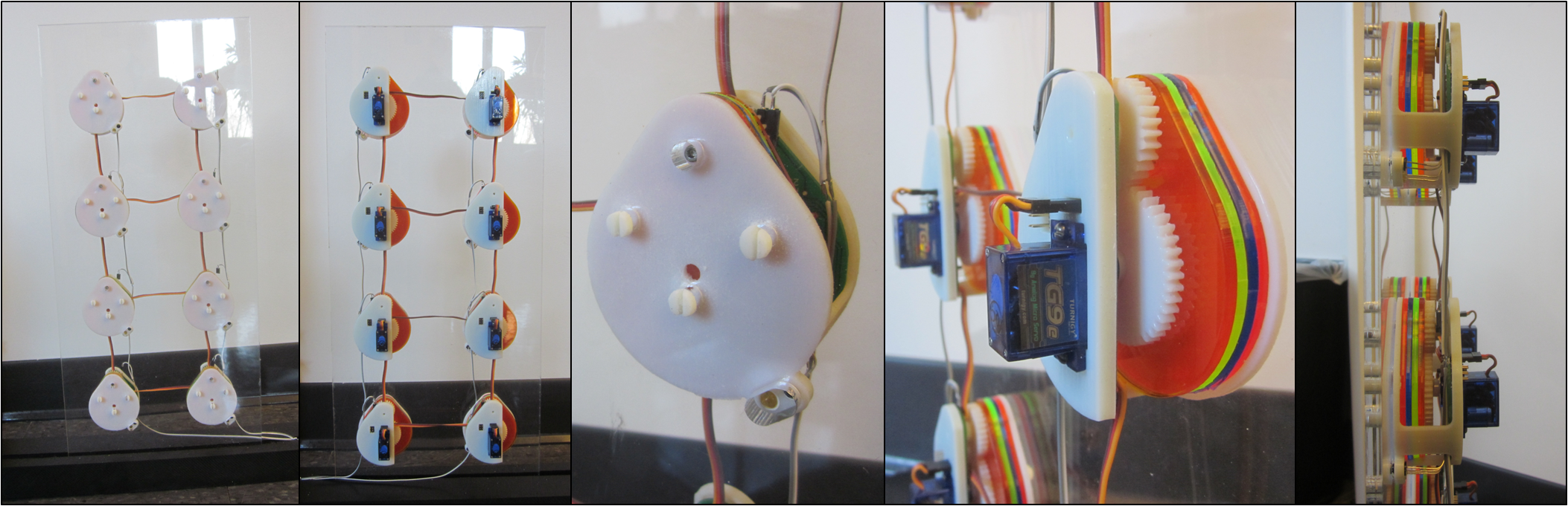
Flower Shell
The flower shell clamps on to the wall and holds all of the flower pieces in place including the servo and gears which can expand/retract the pedals, the controller PCB, the acrylic pedals, and the IR transmitter and receiver for distance sensing. I decided the the quickest option for this would be the 3D printer (To make it cheaper I could have designed it for molding and casting instead). The flower shell (seen above) measures 75x65x28mm, corresponding to the smallest cheap servo I could find on the market.
Besides the shell, I also 3D printed the two gears seen in the picture above
using the gear toolbox embedded in SolidWorks.
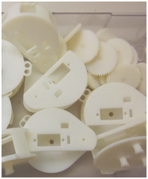
Picture of 3D printed parts (in vero white, ObjectConnex500 printer at Harvard)
Flower Pedals
Since the flower pedals are mostly 2D I decided to cut them out of acryllic in the laser cutter. Each pedal has a groove and a tap to work as the fan-principle. Once all the pieces were cut, I used acryllic glue no. 3 to glue the taps on, and added a metal rod to the center of the tap for strength.
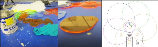
Picture of acrylic pedals cut out in the laser cutter.
Electronics
The PCB is based on an ATtiny44 and is able to control the servo and read inputs from the IR transceiver pair, as well as an optional microphone if desired. It also takes inputs from it's neighbors (their servo outputs) and outputs its own servo signal to them. I designed the electronics in eagle, and everything was done so that it can be milled in the Modella, however, for time concerns I ordered the PCBs from 4PCB.
To late I realized that 4PCB does not do internal cutouts, and so in the end I had to cut out the internals with the modella anyway. (Still saved some time in the end I think, but it wasn't as painless as I had hoped!)
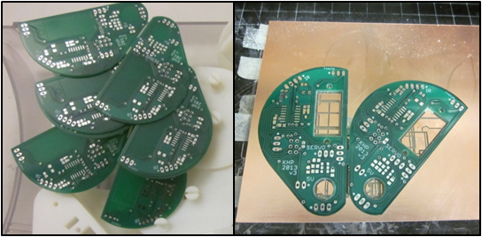
Picture of PCB's manufactured by 4PCB, and extra milling performed in the modella.
Wall and Stand
I ordered a 1/4" clear acryllic sheet to serve as the wall which the agents attach to, and a 1.5"x2"x2foot acryllic rod for the stand. The wall design was simple, holes for the agents to plug into along with a hole for the IR to shine through. The stand I made simply by milling out a slot for the wall and a smaller slot for the power supply and wiring. In the hope that I will some day have time to make an even bigger (and more usefull) office divider I made the stand able to carry two wall sections.
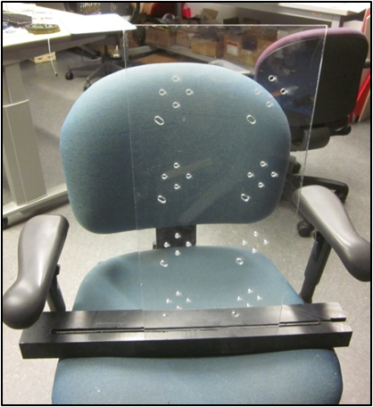
Picture of wall
in acryllic, and stand in nylon.
Simulator
In order to test the outcome of different software strategies I made a simulation tool in Matlab. The simulation tool updates all flowers in a wall in random order at every time step taking their own sensory values, their current state and that of their neighbors into account. The user can choose to excite specific flower sensors at any point in time.
See an example video here.
Software
I have two versions of the final software. In one all the flowers act independently, collapsing the flower when something gets close. The other (currently under construction) reads external interrupts as well to estimate the state of the neighbors and take them into consideration.
The low level software is pretty easy; read from the ADC connected to the IRreceiver 1) when a pulse is sent out, and 2) when no pulses are sent to read the ambient light, translate that number to a servo value, and loop. To avoid too much jitter I do a running average of the last 10 calculated servo values. I translate the IRinput to a distance using a power-function-approximation. The latest software version is here.
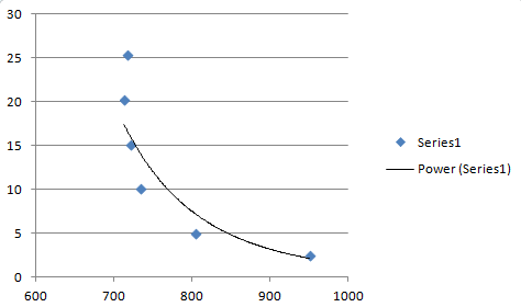
Calibration values of the IRsensor. Bits (on a 10bit scale) on the x-axis, cm up the y-axis.
Final Remarks

The wall ended up looking pretty nice, check out the VIDEO. Of course I wish I had had more time to make it pretty, and make the software run smoother. I do think the wall would be very cool in a bigger scale, but there are a number of things I would improve in a second version:
1. Some dimensions need a bit of tuning to avoid filing(!)
2. I would replace the wiring between neighboring flowers with IRsignals instead (don't know why I didn't think of that before)
3.
Currently the fan-taps are a bit fragile, I would probably beef them up in a new version.
4. I would like to search for a better method of expanding the flower, currently the servo causes the entire flower to be so big in the folded mode that the wall is hardly transparent to begin with...
-Maybe heated wire? (That would be less noisy as well).
5. With more time, I could make the flower-housing moldable to save money.
That being said, there are a number of things I am very happy about with this design; Once I got the idea right, the final assembly was actually rather quick and simple, and I love that the flowers simply snap in place in the wall; also I have gotten a lot of positive comments on the colorful flower pedals. I managed to get the software to be pretty compact and well structured with clever use of interrupts. Finally, I really think that the simulation software saved me a lot of effort in getting the behavior of the wall right.