Electronics Design
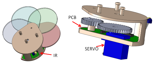
This week is about learning to design electronic circuits. Fortunately I already know how to! :) So I decided to test out a PCB for my final project. To recap the project will be a wall that becomes more or less transparent depending on its surroundings. My initial test agent (made in solidworks) is seen below. Very simply it can fan out its leaves by moving the arm of a small servo, and can react to sensor inputs from an IR sensor/emitter pair.
Leaf-PCB
SolidWorks Assembly:
|
|---|
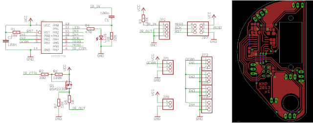
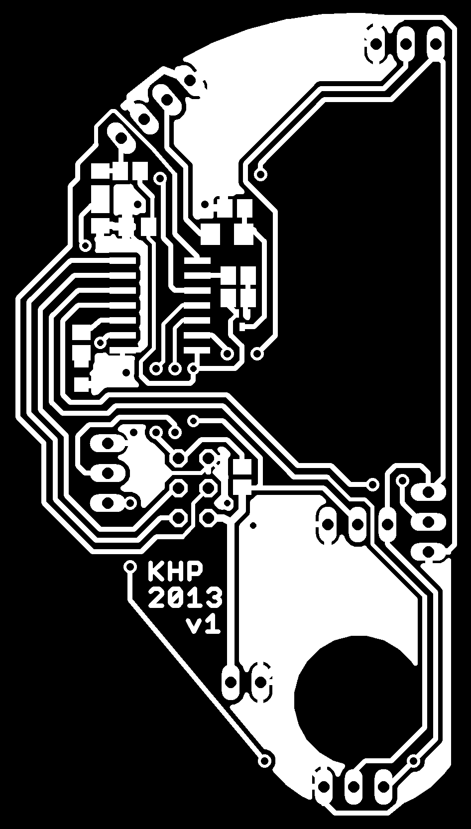
My electronics design is made in Eagle, and is based on an ATTiny44A. Because of lack of output pins it uses the internal crystal, has one LED for debugging, output to drive a servo and an IR emitter, and can read in analog data from an IR receiver. Furthermore it can read in data from other agents in the plane (IN1-4). The input basically corresponds to their servo-drive-signal. Routing was tricky because I tried to keep it all on the same plane, but in the end it worked out without too many vias!
|
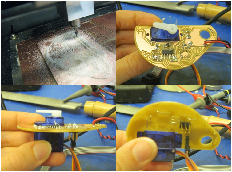
Back to the Modella! :)
|
I wrote a short program in AVRstudio to test that the microcontroller worked. It basically just turns the LED off and on, and rotates the servo. workspace |
| Video here! |