This week, we focused on input devices. Our assignment was to design a board with a sensor and read it. I chose to try the Hall Effect sensor, which detects the proximity and orientation of a magnetic field by varying its voltage output in response. We are using a Hall Effect sensor made by Allegro. You can determine the polarity of an approaching magnet by whether or not the sensor's output voltage goes above or below the baseline voltage of 2.5V. The closer the value gets to either 5V or 0V, the closer the magnet is to the sensor.
Materials and tools:
- Eagle (to design the schematic and board)
- Copper-plated sheet
- Modela milling machine with two sizes of end mills: 1/64” and 1/32”
- Fab modules to communicate directly with the Modela
- Solder, flux, tweezers, copper braid, components
- Magnet for testing
As we have done in previous weeks, I designed my circuit in Eagle and milled it on the Modela. When designing the schematic, I did not have the Hall Effect sensor in any of my Eagle libraries, so I chose another component with the same package as the Allegro sensor (SOT-23W). This way I could be sure the component would have the correct footprint on the board design. Because it was the wrong component, the schematic itself is not accurate (replace the transistor below with the Hall Effect sensor), but the board design works.
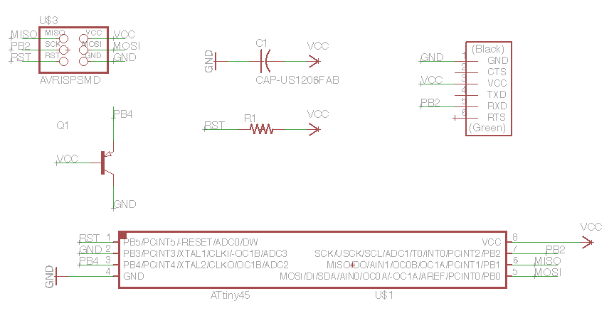
Schematic for microcontroller (ATtiny45) + Hall Effect sensor.
Milling the board on the Modela
For our previous embedded programming week, I learned how to program AVR chips using C. This week, I decided to try programming the ATtiny45 with the Arduino environment. To get set up, I used the High-Low Tech instructions.
To make sure the board was working, I first loaded and tested the LED Blink sketch. Using the SoftwareSerial library, I was able to monitor the serial port. However, when I wrote another sketch to read from the output pin of the Hall Effect sensor, I was unable to determine if it was actually responding to the presence of a magnet because the numbers coming across the serial port did not appear to be changing in relation to anything in particular.
Next, I attempted to use the Arduino function ReadAnalogVoltage(), but was unable to load that sketch onto the ATtiny45 due to the size of the sketch. Ermal told me that the memory required to output a float to the serial port was more than my ATtiny45 could handle, so I may want to try using a different microcontroller if I stick with the Arduino environment. So, in a last attempt to understand whether or not my Hall Effect sensor was reading the orientation and proximity of a magnetic field correctly, I turned to the oscilloscope.
Testing Hall Effect with oscilloscope
The readings did move between 0 and 5V according to both the orientation and proximity of a magnet, so I believe the sensor is working. My next steps are to write Arduino code to read these voltage fluctuations, but if my ATtiny45 does not have enough memory to do this using Arduino libraries, I will switch back to C for this sensor...