This week, we focused on output devices. Our assignment was to design a board with an output device and program it. This week I made a board for an RGB LED output, and also started making a Fabduino (a fabable Arduino-compatible board) for further experimentation with inputs and outputs. For the Fabduino, I relied on tutorials from the fab lab at AS220 in Providence, as well as examples from previous years produced by Tiffany Tseng and Austin Lee.
Materials and tools:
- Eagle (to design the schematic and board)
- Copper-plated sheet
- Modela milling machine with two sizes of end mills: 1/64” and 1/32”
- Fab modules to communicate directly with the Modela
- Solder, flux, tweezers, copper braid, components
As we have done in previous weeks, I designed my circuit in Eagle and milled it on the Modela. My first schematic was wrong, as I incorrectly placed the pull-up resistor. As a result, I had to hack up my board with wires and a razor.
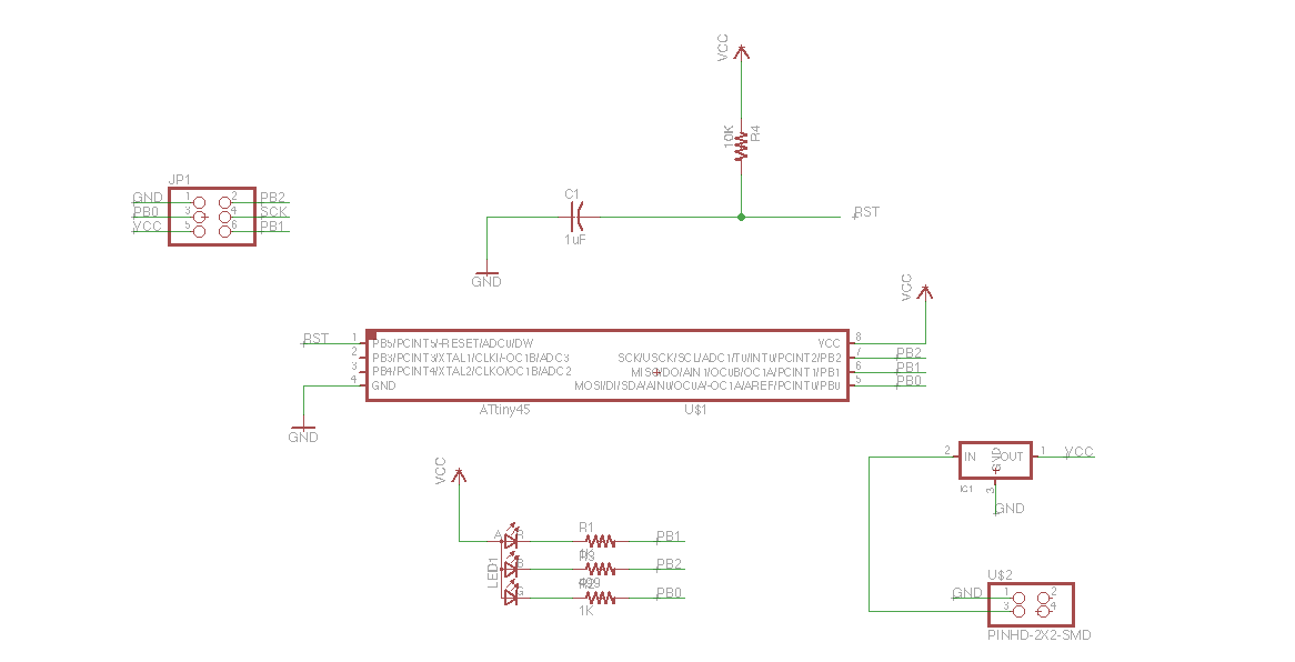
Schematic for microcontroller (ATtiny45) + RGB LED.
Unfortunately, when I tried uploading code to the board (both the make file and Arduino code) I encountered an error: "avrdude: initialization failed, rc=-1. Double check connections and try again, or use -F to override this check." I know this is a common error and so I tried to debug by first testing the connections with a multimeter and reflowing the solder. Unfortunately, this did not work. Next, I tested the LED to see if it was working independently (to check some of the wiring).
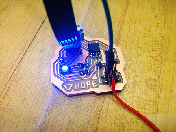
At least it lights up...
I discovered in going through my schematic that I had incorrectly placed my pull-up resistor, so I hacked up my board to correctly wire it. However, I still recieved the same error message. I'll debug again after class with a classmate!