Electronics Design
This week I learned how to design a circuits board in software Eagle.
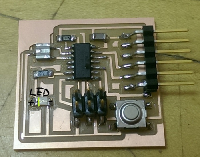
Based on the helloecho board, which the board echos the message from a input device,
then send back the exact the same message to an out put device, I add one LED and one
button to the board.
-------------
Draw Schematic and Route the board
I followed the Eagle Tutorial , the software is easy to use and straight forward.
I imported the FAB Components Library , and drag the needed components to the schematic.
Once I finished the schematic, I route the wire in the board diagram.
-------------
-------------
-------------
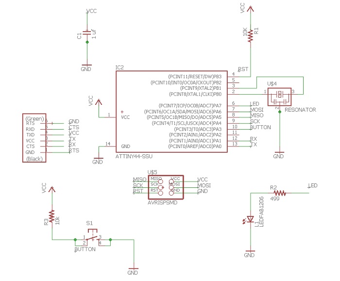
schematic diagram
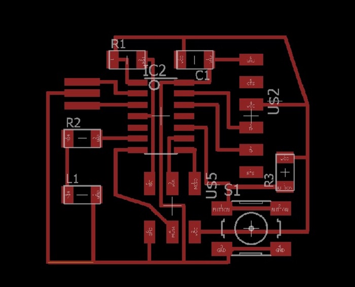
the board
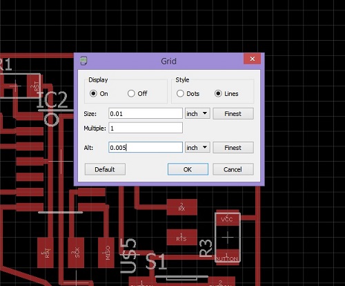
Sometimes, it is hard to space the wire between the components and maintain
enough clearance between the wire and tab. I changed the grid size to 0.01 inch
so that I had finer control to move around.
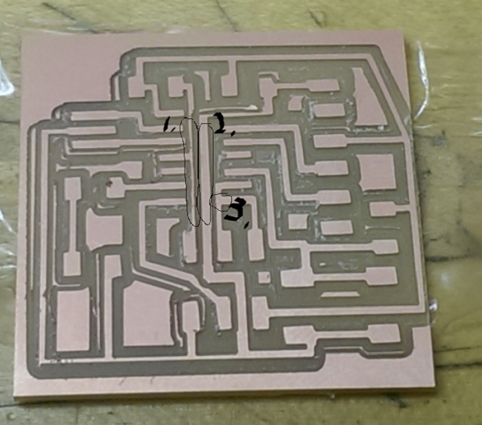
The milled board is not perfect, the 1. wire is really thin, the 2. wire is really fat
but they are the same width in the PNG image, not sure what caused it
The mill machine does not mill the pin 8 on ATTINY 44 and the line next to it shown in 3.
I use a razor blade cut off the copper in 3. and solder the components on the board.
The LED has polarity. I connected the annode to pin 6 of ATTINY. So in the program, I need
to specify the mode of pin 6 should send out current rather than draw current from the board.
-------------
-------------
-------------