Week 11: Microphone Board
In line with last week's project, in which I worked on the output portions of my final project, this week I plan to work on the coding and signal processing portion of my final project. Since in order to perform signal processing, you need a signal to process, I needed some way to get music into my board, and I needed to incorporate a sensor somehow. Under these two criteria, I decided to produce a microphone board that would perform FFT on the input, and then output a visual representation of the extracted pitch or beat information via an LED.
I began with Prof. Gershenfield's microphone board. While reproducing it in EAGLE and adding an LED, the main problem I encountered was that there was an unlabeled "IC2 3.3V". I thought that this was a MOSFET since it had similar packaging, but if it was a MOSFET, many aspects of the labeling didn't make sense, including the 3.3V and the fact that its terminals were "out", "in" and "gnd", and not anything more MOSFET-y.
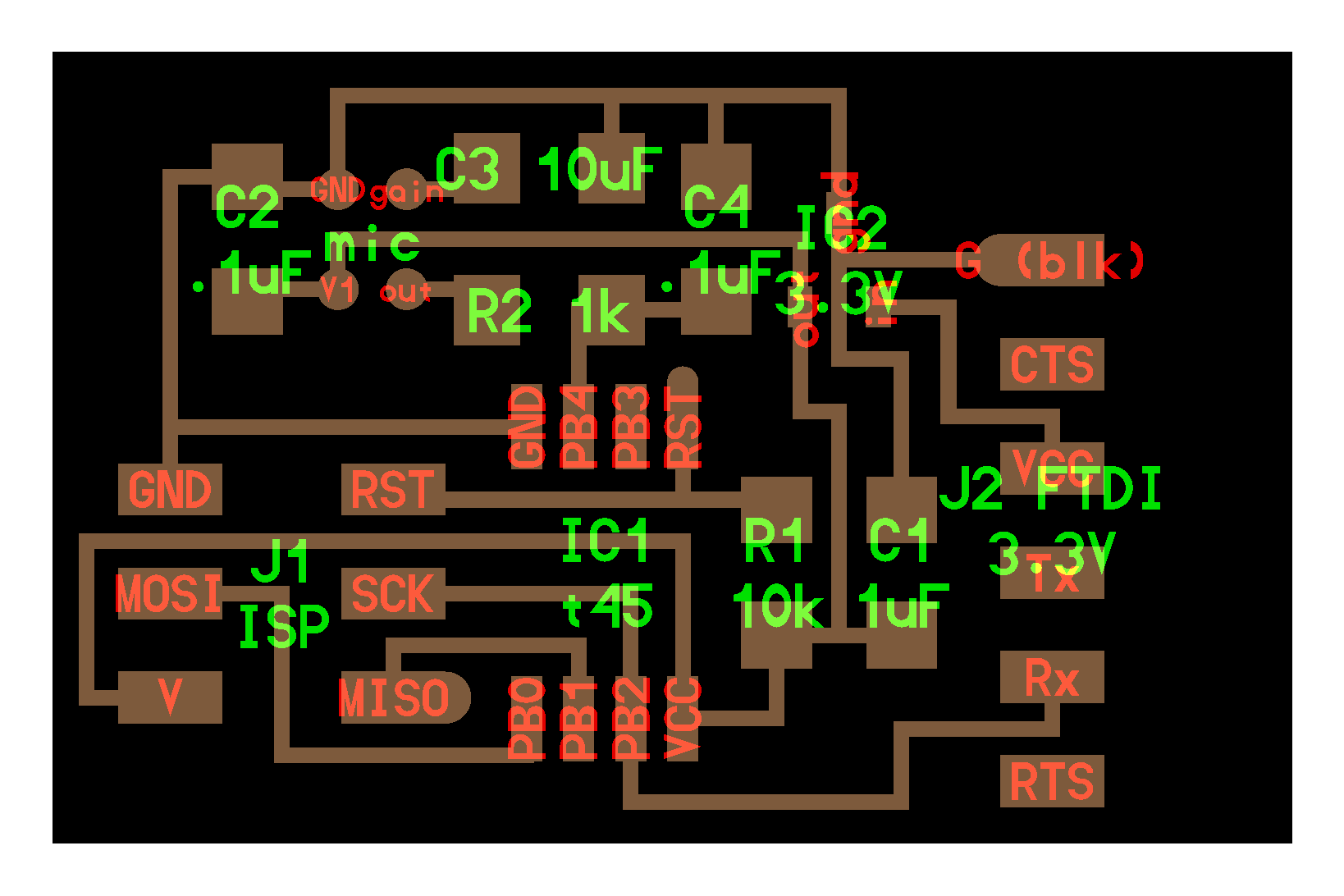
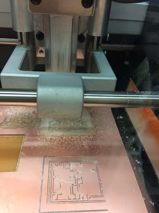
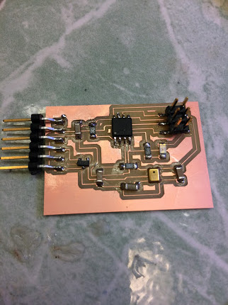
PSA: IC2 is not a MOSFET. It's a voltage regulator. Fabrication went well after I figured that out. The microphone was the most difficult part, honestly: because its terminals were completely flush against the underneath side of the package, reflow soldering was required to attach it. Unfortunately, I had an exam during the reflow soldering recitation, so I had to ask Gavin how to reflow solder things. The answer is that reflow soldering is just 1) placing solder paste on all of the contacts 2) placing your component on the solder and 3) while pressing down, using a hot air gun to melt the solder paste and thus solder the part.
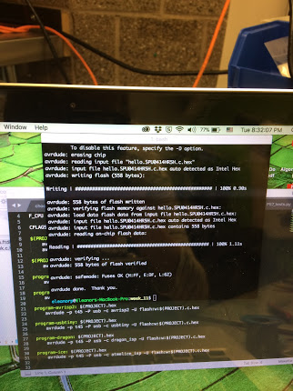
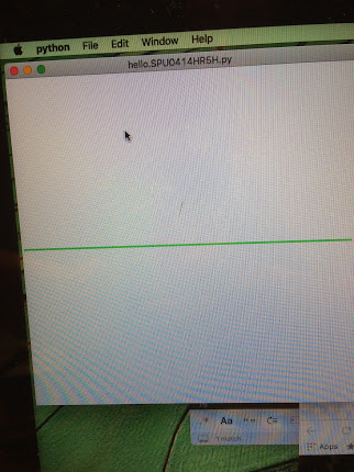
Unfortunately, all was not well. When I plugged in the board, I got this. It's not a flatline all the time, there are some random jitters, but they don't line up with background noise.
The multimeter shows that there is nothing coming out of the microphone's output, which implies there's something installed wrong. Unfortunately, the parallel remover tool was broken, so I used the hot air gun instead to remove the microphone. I then removed the old solder with copper braid, and re-did the reflow soldering. This time it worked!
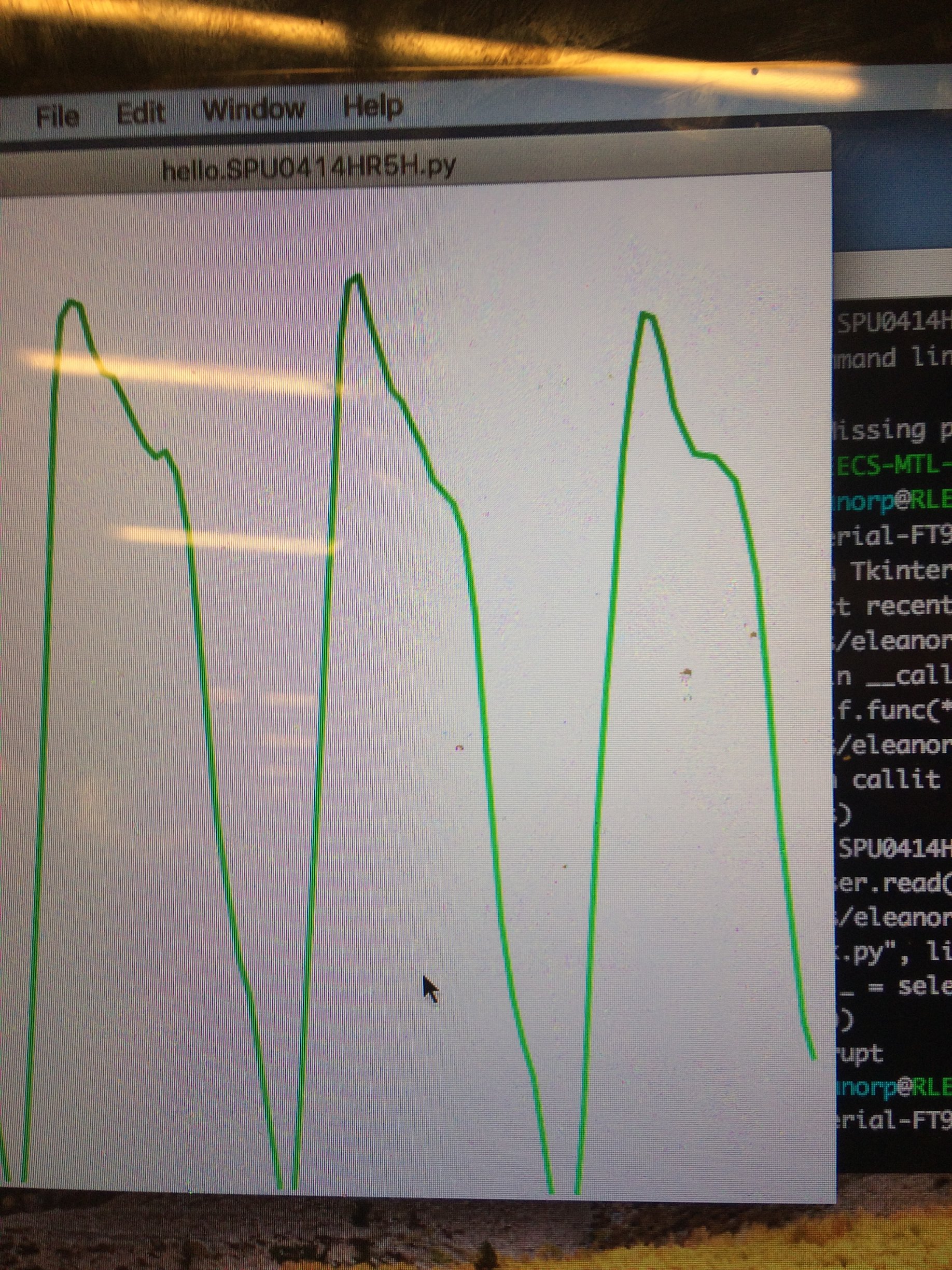
Unfortunately, the quality on the audio does not appear to be nice enough to perform useful analysis on the signal, so I'll be working on getting a working auxiliary jack that can take sound directly from an iPhone before I can start on the realtime signal analysis portion of my final project.