Week 12: Interface and Application Programming
Continuing on the project from week 7, which was using PWM to get custom colors out of an RGB LED, to produce a sort of real-life color-picker, I now wanted to give the color-picker an actual interface (as opposed to picking colors via adding hex values to the code and flashing the new code to the chip).
Taking Color Input
I started with a basic set of colors that didn't require PWM to produce, in order to get the communication and user interface parts of this week's project under control first. With the PWM colors, I knew I was going to need a main loop - of flashing the lights in sequence in order to get custom colors - and an interrupt handler, which would detect when there was an incoming transmission and change the color-determining variables in appropriate ways.. So I built all of the communications-handling code in an interrupt handler, bound to logic changes on PCINT0, which is pin 13 on the ATTiny44.
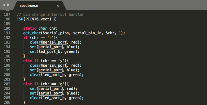
As you can see, the interrupt handler reads in a byte to chr, and then checks if chr is a series of values corresponding to colors. 'y' represents yellow, for example. It then sets the values of the RGB pins based on this input. The get_char function is taken from Prof. Gershenfield's code; it just checks the value on the Rx pin at the appropriate intervals and transcribes those values to various bits in the resulting byte.
Talking To The Chip
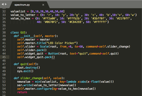
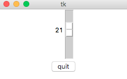
I then built an interface with Tkinter to talk to the chip. The interface is very simple; it uses a Tkinter's Scale widget - a sort of slider - to take numerical input on a scale of 0 to 70, and it also has a button that quits the program. The slider has a function bound to it that is called whenever there are changes to its value. This slider is what actually does communication with the chip. First, it rounds off the values from the slider to one of seven continuous values representing each of the seven non-PWM colors the RGB LED can display. Then it 1) looks up a char to represent that discrete color value, and sends it to the chip over the serial connection that was set up as the GUI was being set up, and 2) looks up a hexadecimal color value that corresponds to the discrete color value that the RGB LED is going to change to, and changes the background of the Tkinter window to that color, just to give the user immediate and intuitive feedback about what this slider actually does.
As for the rest of the code, I also borrowed code for setting up the serial communication from Prof. Gershenfield's term.py. You may also note that I used ttkinter and not tkinter; ttkinter contains nicer-looking, customizable versions of the standard tkinter widgets. I did this because the standard tkinter widgets are very, uh, retro.
Behold, A Working Color Picker!
Here is my C code, here is the makefile, and here is the Python script that makes the GUI and talks to the chip.
The thing that this color picker does not do that I would have liked it to do is allow the user to pick colors that can't be achieved by anything other than PWM, i.e. oranges, yellow-greens, and so on. Unfortunately, I could not get this working. The problem is that either I have completely misunderstood the interrupt code on which this is modeled, or he interrupt code doesn't work the way you think it does. I thought initially from reading the code that what happens is 1) the initial bit of the transmission comes in 2) the interrupt handler is called 3) the interrupt handler reads the char with get_char, adds it to the buffer, and passes that plus an extra new string to the Python program that it's communicating with.
However, this actually isn't what's happening. get_char has a loop in it at the very beginning that waits for the Rx pin to have a 1 on it before reading a character. And the interrupt handler is activated by that initial 1 that get-char would be waiting for, and this appears to throw off the timing of transcribing the rest of the byte such that interrupt such that the first byte you send is actually lost. (Not including the wait-loop in get_char does not resolve the issue.) The only reason that the following bytes are read is because a second interrupt occurs immediately after that first one finishes, causing the program to just sit in the "waiting for the initial high logic" loop until the Python program that it's talking to sends another character. This basically means that the code never returns to the initial loop - which means you can't do PWM-based color displaying, because the only code that ever runs is the interrupt handler and get_char. I'll come back to this problem if I have time before the final project, because it seems likely that I have just missed something.