Week 7: Embedded Programming
There will be a video with quickly flashing lights in this post. I feel the need to warn because, the video in question is unpleasant for even me to look at, and I don't want anybody to have a seizure or anything.
Some Exciting Facts About Microcontroller Programming With The avr/io.h Library
Since I knew nothing about microcontroller programming before starting this class, there were many things I did not understand about the code. I'm going to do a quick walk-through of the hello.ftdi.44.blink.c code, for future reference of future students. avr-tutorials.com was actually a very helpful reference; the attiny44 datasheet is nice, but a bit verbose for a quick reference. I'll include screenshots of the relevant code as I go along.
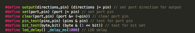
The macros at the top of the file are just utility functions used to interact with pins on the microcontroller. Pretty much all of the all-caps letters-and-numbers combinations are aliases referring to either pins or internal registers in the microcontroller, provided by the avr/io.h library. PA0 through PA7 are the seven pins on port A; PB0 through PB7 are the seven pins on port B. They both have integer values. DDRA is an 8-bit (okay, everything on this microcontroller is eight bits because it's an 8-bit microcontroller) register where each bit represents whether PA7 through PA0 is an input or an output pin. If you wanted to modify the direction on a pin starting with PB, you'd need DDRB. Similarly, PORTA represents the logic values being currently outputted on the physical pins of port A. Port B is represented by PORTB. If you wanted to read values from a pin, you'd use PINA or PINB instead.
As you can see, the macros defined at the top are based on bitwise operators, and are pretty intuitive if you know that typically, "port", "directions", "pins", or "bytes" are the contents of the relevant register, and pin is a bitstring representing PAx or PBx, which has the value of a byte with a 1 in the xth bit and zeroes elsewhere. led_delay is based on an imported delay function, _delay_ms.

If you need the aliases for any registers, define them as constants, and if you need to be able to use pin PAx or PBx with macros, you'll have to define as a constant the relevant bitstring (again, eight bits, with the xth bit 1 and all other bits 0), with #define your_pin (1 << Pxx).
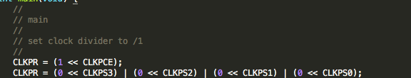
Inside of main, the lines involving CLKPR are setting various bits of CLKPR register, which appears to set a clock prescaler, which is necessary, but not important for most of the code you might write. Before you make use of any pins in main, you have to 1) clear their values so they aren't outputting anything and 2) set them as input or output, with the clear and output functions respectively.
My Actual Project: Programming an IRL Color Picker
I had considered, in my final project, having the color of the light change in response to the sound being produced by the speaker - maybe louder sounds would get a color that was closer to blue on the spectrum, and quieter sounds would get a color that was closer to red on the spectrum. For that to happen, I needed to be able to get the LED to produce colors that were not just the primary colors. Basically, I wanted a color picker, but, as all the kids are saying these days, IRL. (Or maybe the kids aren't saying that. I have no idea; I'm 22 and therefore ancient.)
I'd originally imagined doing this by sending different levels of voltage to the pins for red, green and blue on the RGB LED - thus creating differences in brightness between the LEDs and allowing color mixing - but as soon as I started working with the actual io library, I realized this would not work. Computers don't usually "think" in terms of analog voltages. I go to MIT; I really should have realized this earlier.
So I had to think of a different color-mixing approach. It seemed to me that, given the glitch that brains have where they can't follow flashes faster than a certain speed, flashing the LED between colors really quickly should give an illusion that it was emitting a steady color similar to both. And if you switched up the ratio between the time that the green LED was lit and the time the blue LED was lit, then you'd get a color that was greener or bluer.
To accomplish this, I changed the led_delay macro to take an argument delay, so that the delay would be adjustable, and I added a delay between each of the LEDs turning off and its successor turning on proportional to the fraction of that color I wanted the resulting LED to have.
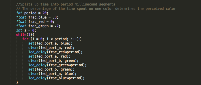
This worked. But it turns out that the overall period of the color-switching, as determined by the variable period in the code above, is really important. If your color switching isn't fast enough, you'll just get a flashing light that is mildly painful to look at.
5ms period works much better.