Week Two: Computer-Controlled Cutting
This week there were two techniques we learned: project management and computer-controlled cutting. The computer-controlled cutting module was divided into two parts: using the laser cutter, and using the vinyl cutter.
Homeomorphic endofunctors mapping submanifolds of a Hilbert space
The 'project management section was not very difficult for me, since 6-3 has a fair amount of courses that use Git - the most fiddly part, getting the SSL keys set up, went off without a hitch. I must say, I am very glad that I'm not having to learn git during this class, because git - despite being powerful, rather elegant in design, and utterly ubiquitous - infamously has a stupid user interface. (The way it was explained to me was that git as we know it was originally intended by Linus Torvalds to be the "plumbing" for a more user-friendly distributed version control system, but then people started using it and he never got a chance to put in the "porcelain" over the top that would make git user-friendly, so the bizarre UI remained. I tell this story because it is probably my favorite instance of the concept of "technical debt".) This interactive git tutorial was helpful for me at first. You might find it helpful too, if you're new to git and people keep telling you things like oh yeah! git gets easier once you get that branches are homeomorphic endofunctors mapping submanifolds of a Hilbert space!" and all you want to do is un-commit something, dang it.
Vinyl cutting: Everyone gets a laptop sticker!
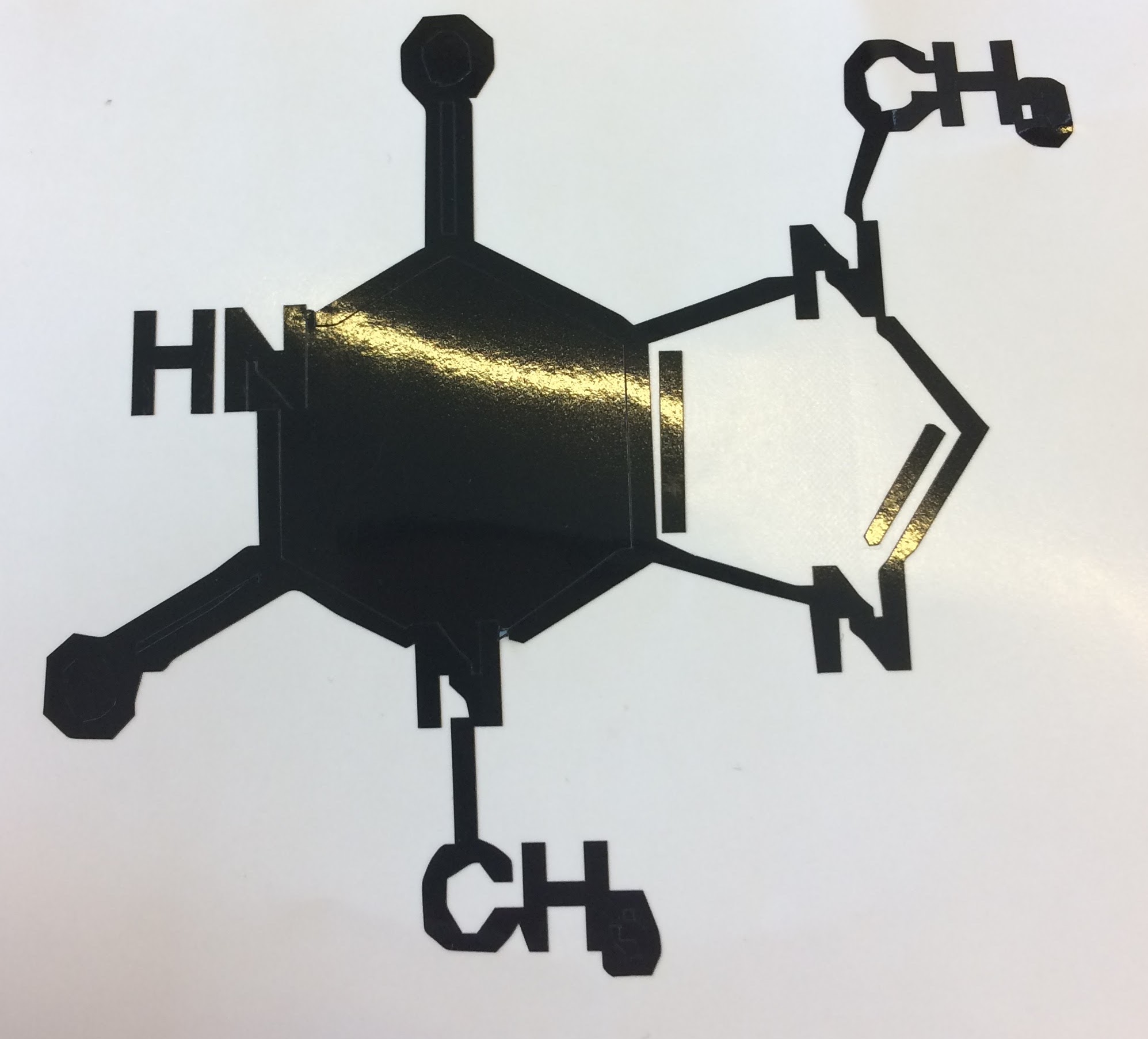
After our TA told us that it was likely that everyone would forget about the vinyl cutter assignment and then there would be a huge rush for the vinyl cutter Tuesday evening, I decided to do my vinyl cutting first. I didn't have any good ideas at first on what to cut on the vinyl cutter for last week; I already have a laptop sticker, which takes up my entire laptop. So I surveyed my mom and a couple of my friends for ideas for laptop stickers that they wanted, saying I would make them on a first come-first serve basis. My mother, a biology teacher, wanted a theobromine molecule for her classroom (theobromine being the "active ingredient" in chocolate.)

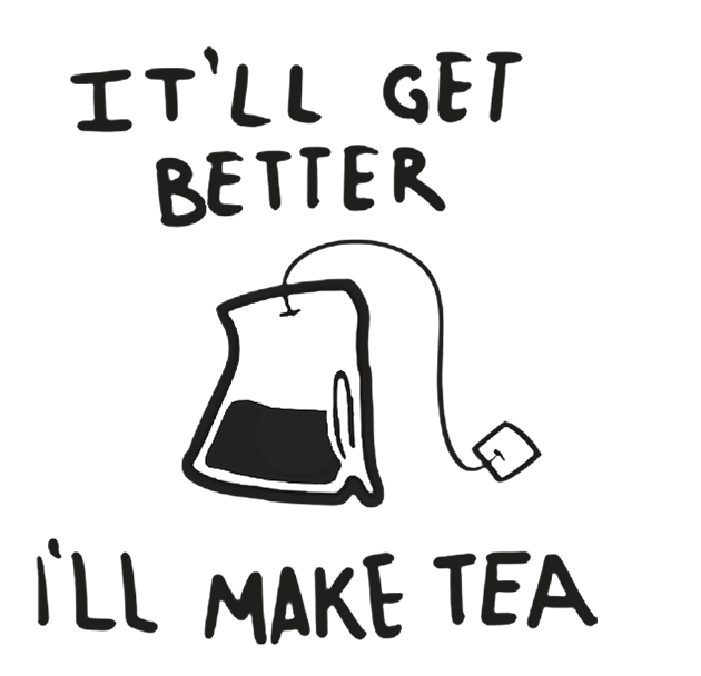
My friend Maura, whose GRT once reportedly told her that "tea is, like, your life" wanted a cute tea-related sticker.

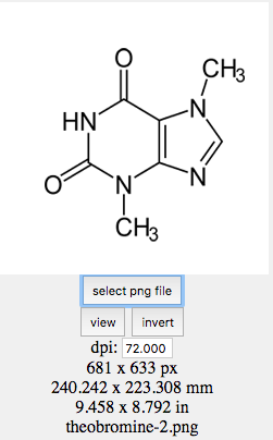
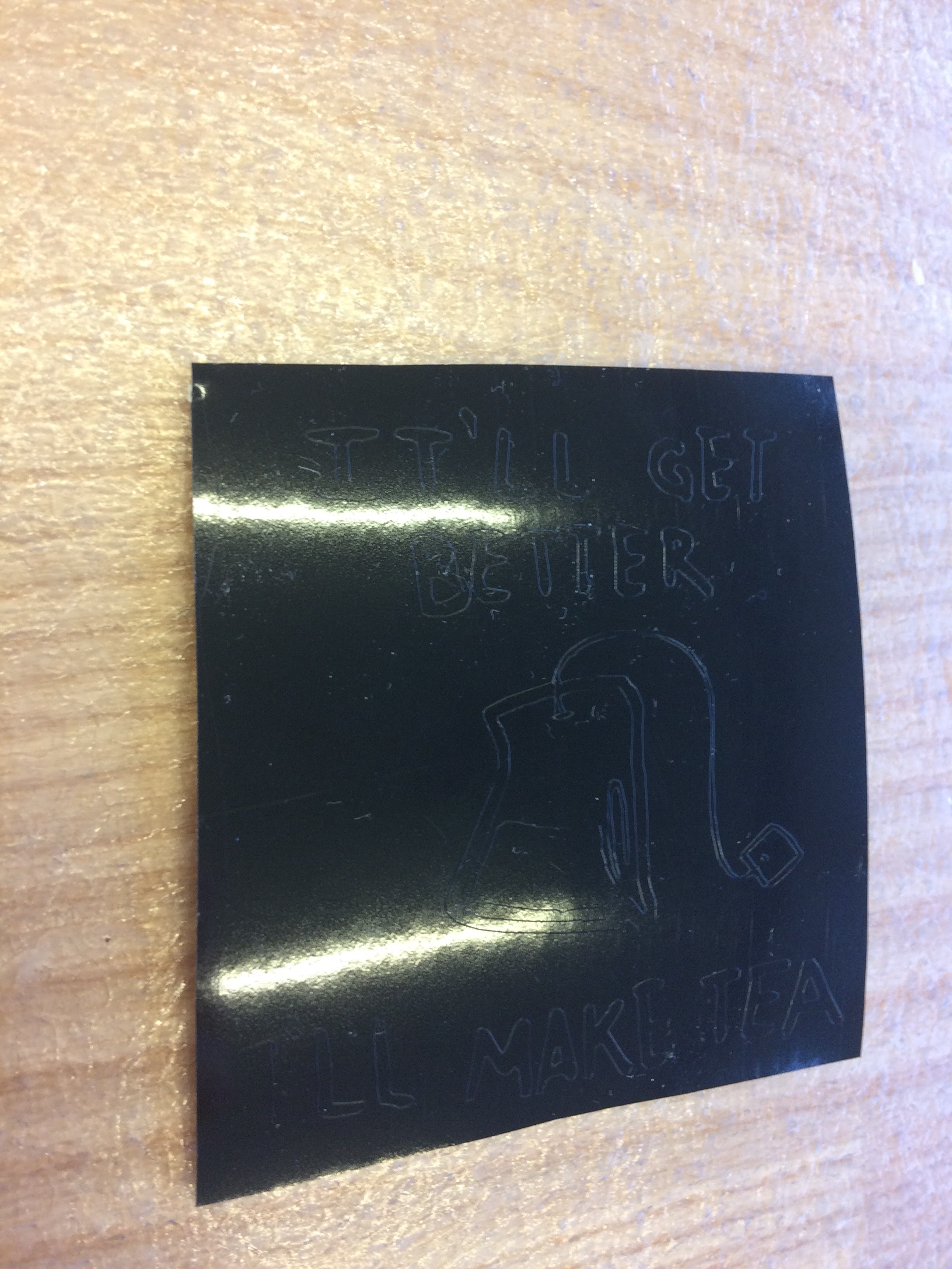
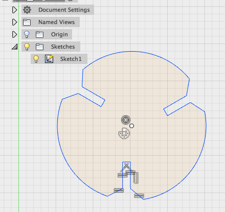
My main issue with doing this was difficulties with resolution. Very high-resolution images are best, and large images will do in a pinch, but in that case the image needs to be properly scaled down as well, else you'll just get a really big sticker. My first draft of the theobromine was definitely not from a high-enough resolution image, as you can see in the following image:
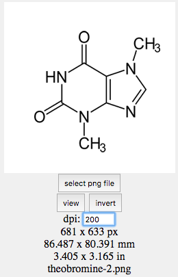
I then upsampled the image in a Photoshop document the same size as the original image, but with a resolution of 300ppi, cleaning up the edges manually with the color select and paintbucket tools, then fed it into the laser cutter. I realized about five seconds after the vinyl cutter started cutting that the image was too big - it turns out that mods also needs to know what the desired DPI is, and dpi determines the image size. mods knows what the dpi is because it's in the image metadata, and if you did not set the dpi of the image in your image editing program, because you're a digital artist who doesn't print things, then it will use whatever your image editor's default dpi was - in this case, 72dpi. And that's what caused the image to be way too big.
Next, I worked on Maura's sticker. The original image was 1) low-resolution and 2) in color. I copy-pasted the image into a higher ppi Photoshop document, then turned the image into black and white, by using the color select tool on the colored regions and then making them black. Some parts of the image that had a color-to-black border, which meant that in black and white those sections would just merge together, so I added a gap between them so they'd be read as two different blocks of color. Then I printed it!
Laser Cutting: modern art
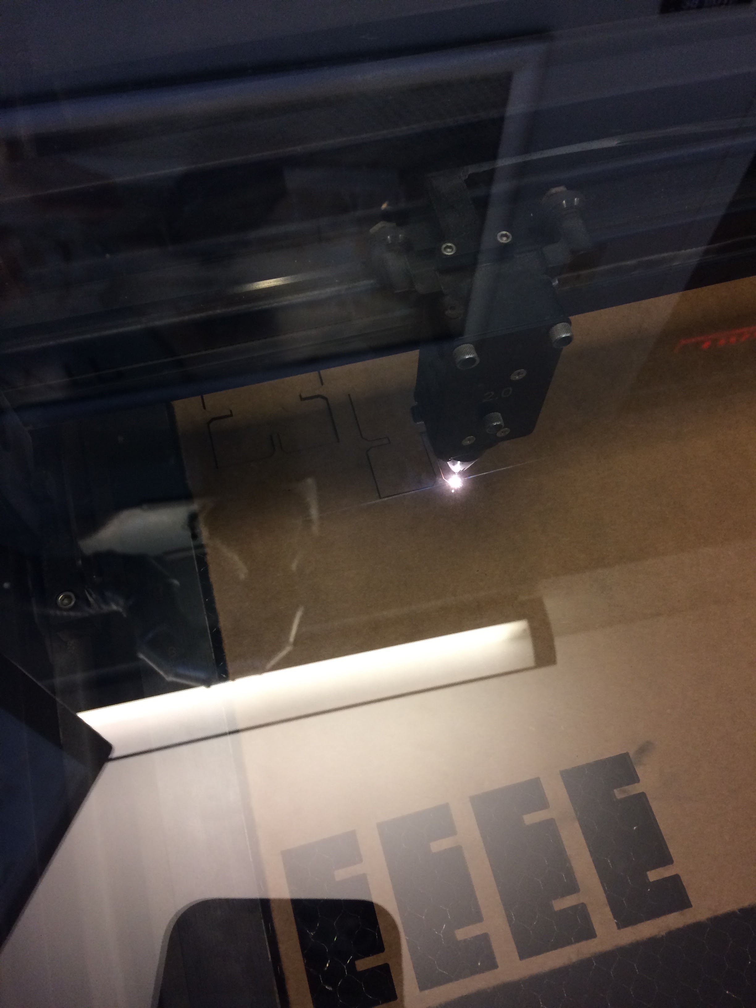
I started out by measuring the kerf and figuring out the needed slot size at the same time, by creating a test comb. I had chosen the program Fusion360 earlier, and I decided that I should use it again here, even though a non-parametric program like Rhino or a drawing program like Inkscape would also work, because I wanted to become more comfortable with CAD-like programs. Plus, I planned to use the parametric capabilities, and the entire patching-over-Rhino's-issues-with-Grasshopper thing seemed a little silly when I had a program that could do that sort of thing natively. In creating this drawing, I learned how to use sketch constraints while doing this drawing.
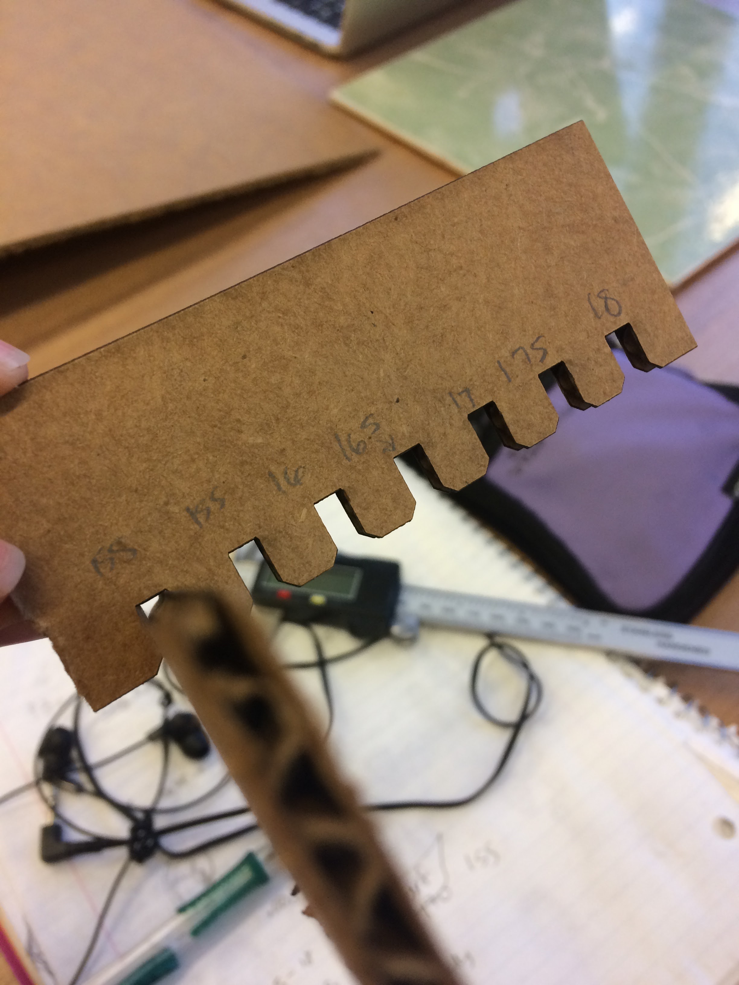
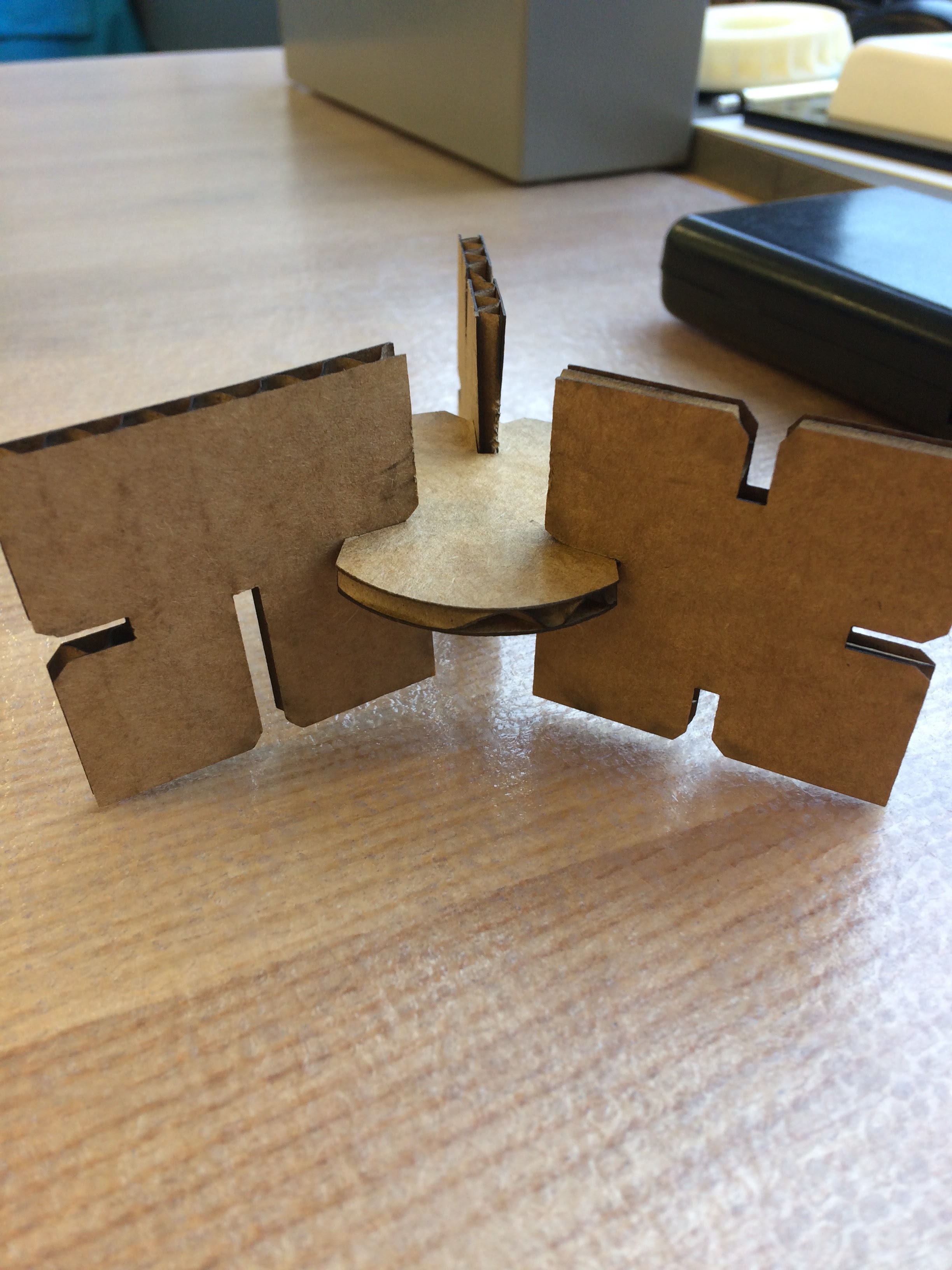
The setup of the test comb was a series of slots with campfers along a long piece of cardboard, slowly increasing in width as you went along the comb. The idea was that I could measure the size of the slots and compare it to the slot width on the drawing to determine the kerf, and that I could also try various widths of slot to see what held more securely. Sizes ranged from 0.18in to 0.12 in.
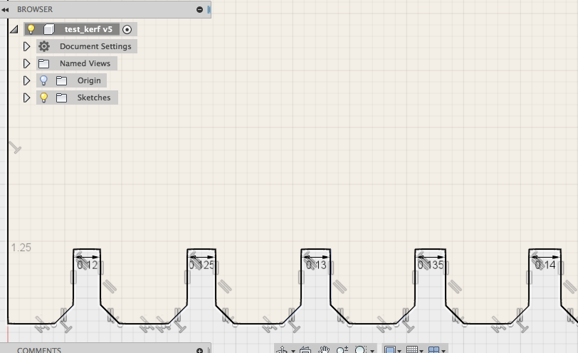
After using the laser cutter to actually cut out my design, I discovered that 0.12in on the drawing gave a tight fit as slot width. .015in was the kerf that I got.
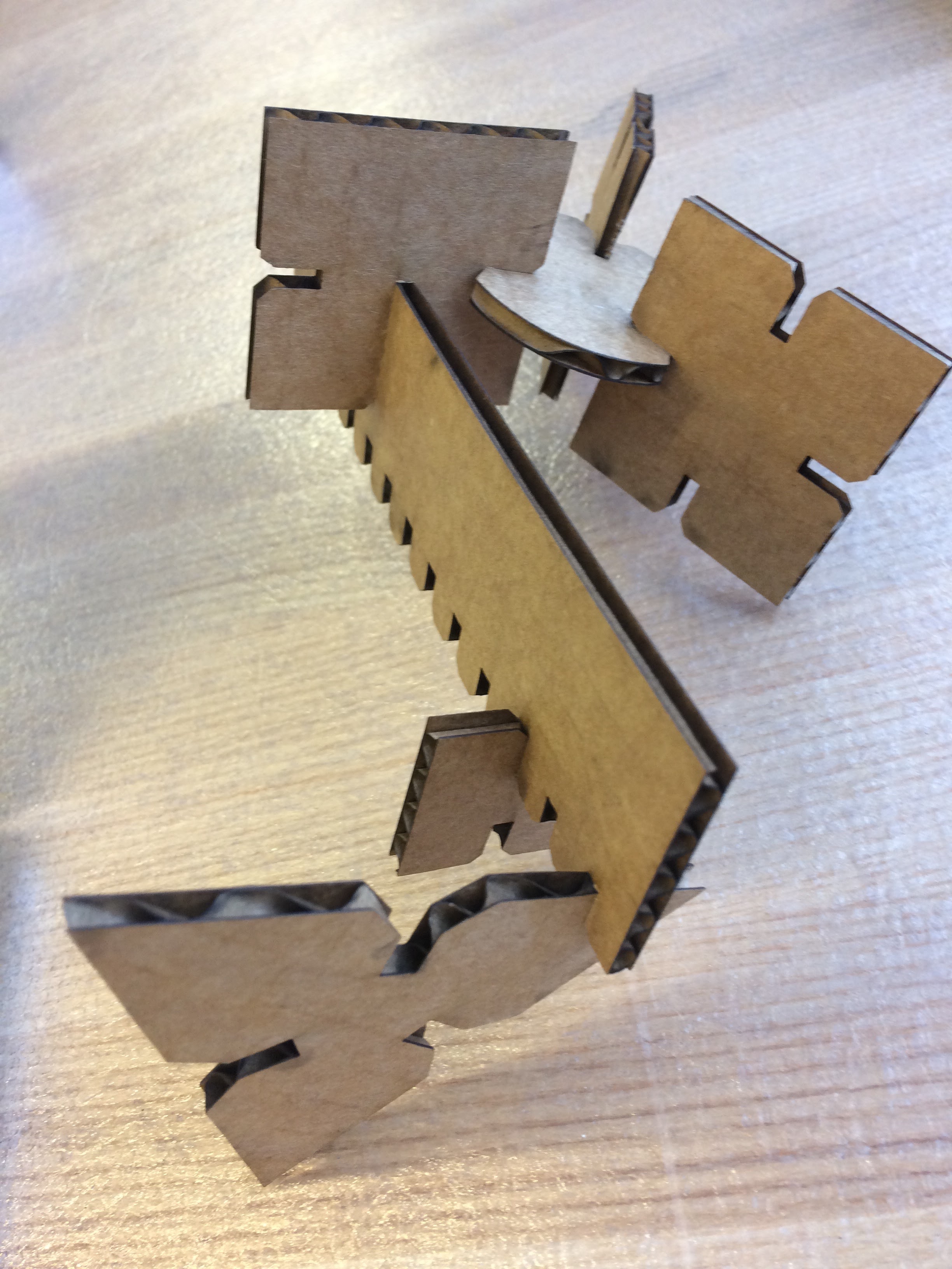
Emboldened by my success, I moved on to the press-fit construction kit. Unfortunately, I did not appear to get the memo about being allowed to build a moving hand or a gyroscope out of cardboard, so I simply replicated the pieces in the example (gik.cad, on the course website) in Fusion360, as an exercise in making CAD sketches.
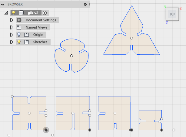
My main issue in trying to reproduce these was rotating the "slots with campfer" modules I had already created for the test comb, so that they would line up with the different edges of the pieces, particularly the circular and triangular ones, and ensuring that the location of the slots on each side was the same. After a fair amount of time spent trying to figure out how to do this by hand, I discovered the existence of the Circular Pattern tool, and all was solved! The Circular Pattern tool is located under Sketch>Circular Pattern, and allows you to specify a point around which the selected part of the drawing will be copied in a circular pattern, and how many copies to make.
Having discovered this while making the circular and triangular pieces, I then applied it to the rectangular pieces, and it was certainly helpful, since copy-pasting things in Fusion360 tends to somehow lead to duplicate lines aside from the ones you deliberately copy-pasted, lines which are not visible because they precisely overlap with the old lines, but make themselves known any time you try to move the figure you copied, and lines which the laser cutter can see and sometimes tries to cut along. I then discovered there was a similar rectangular pattern tool, which replicates a particular shape along a particular line, which I used to make a new, more comprehensive test comb with more slots.
The laser-cutting itself was uneventful.
You could make a tiny turbine.
Or modern art!