Danielle Aspitz
MAS.863 | How to Make (Almost) Anything
FINAL PROJECT
This week was one of the most intense weeks of my life.
_1. Research Cymatics
2. Design Form + Fabricate "Orb"
3. Test Speakers + Order SuperBright LEDs
4. Design Master Controller
5. Solder and Program
6. Fabricate Knobs
7. Design + Fabricate Slave Board
8. Design + Fabricate LED board
9. Solder and Program
10. Lasercut Middle Disk for Light + Discover Stand
11. Connect Boards
12. Write Code
13. Create LED holder + 3D Print Speaker holder
14. Test + Troubleshoot
15. 3D Print Final Orb Components
16. Fabricate Turntable
17. Waterproof
18. Assemble
19. FINAL presentation
20. Adjustments
21. Further Experimentation
_
1. Research Cymatics
After prototyping the motors and also testing out solenoids and considering electromagnets to trigger and release a sort of clamp... I finally decided upon speakers to control the ripples. In retrospect a part of me wishes I had designed the setup and then tested out the different types of movement because that way my experiments and conclusions could be more consistent.[upon writing this I felt bad that I didn't try it with the setup and so I did [see bottom - experiments section]. I also wish I had tested more thoroughly the placement of each device and see if that affects how much control you can get with the creation of ripples. I began by researching Cymatics to find which frequencies were best for the effects I was after.
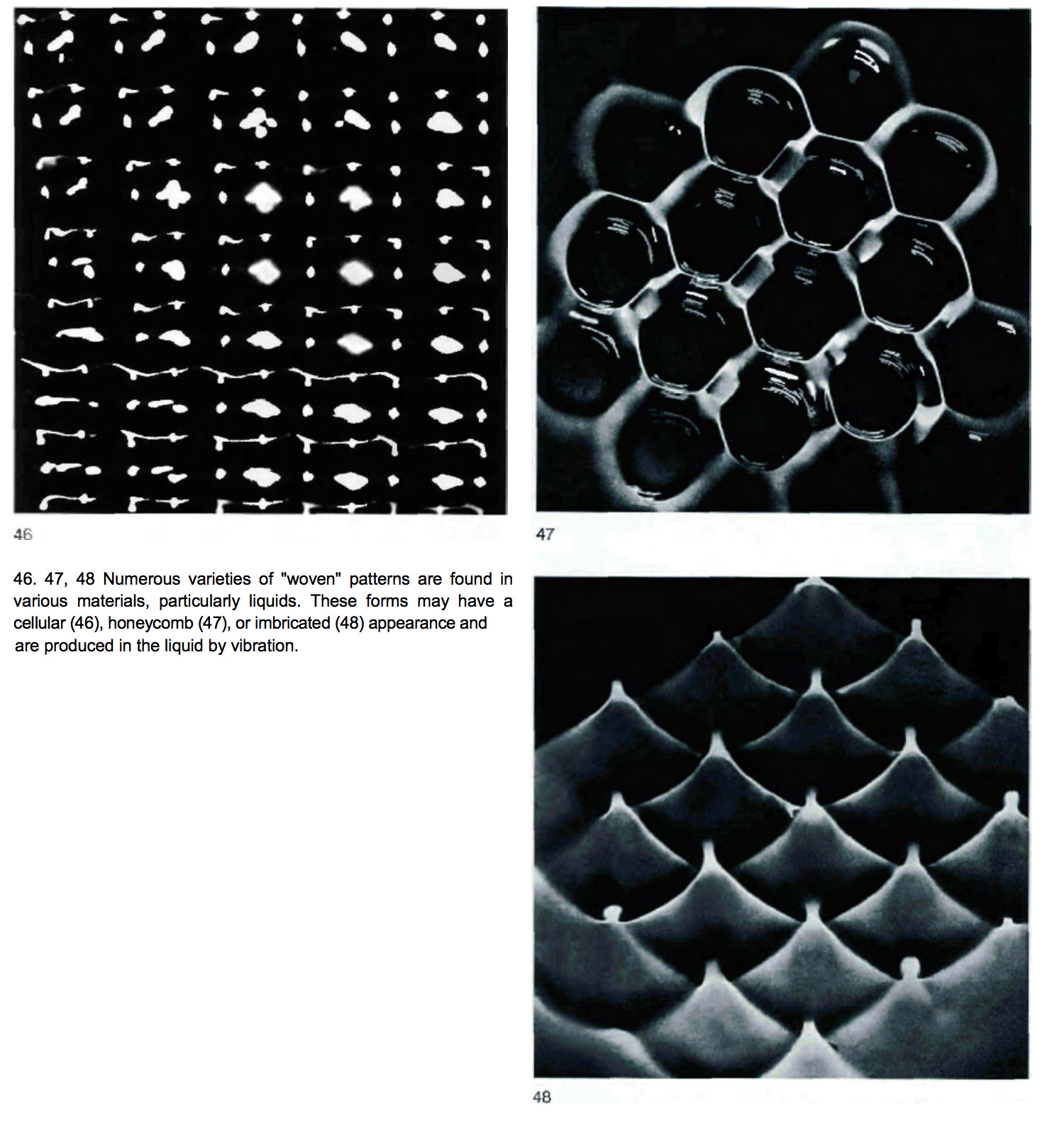
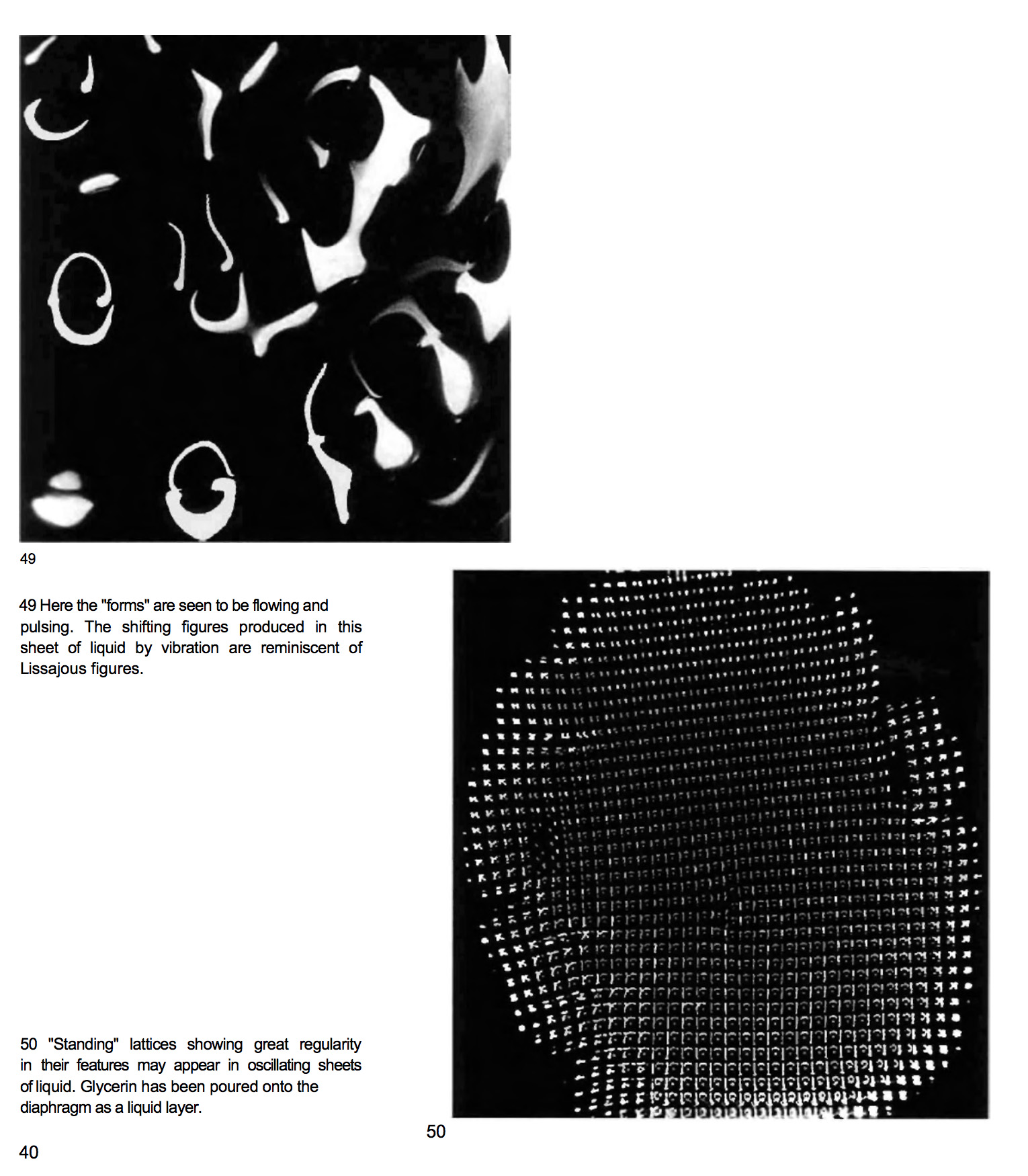
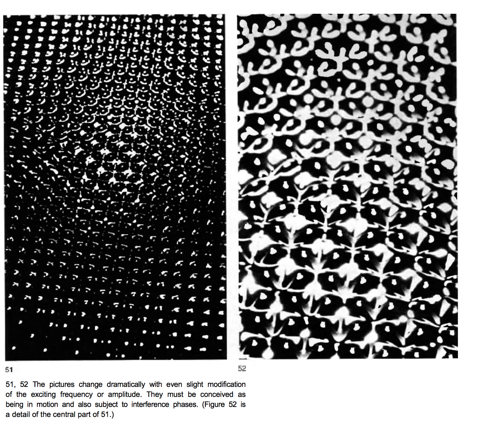
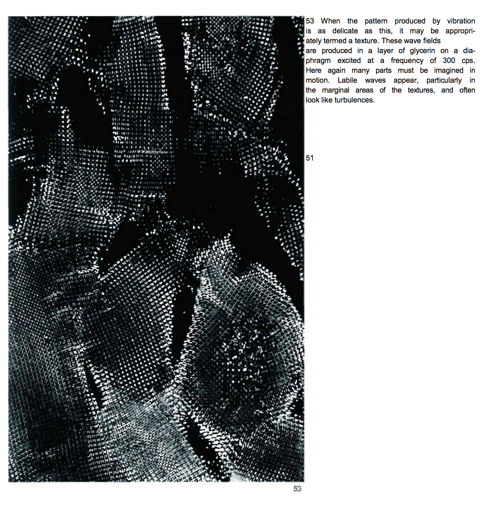
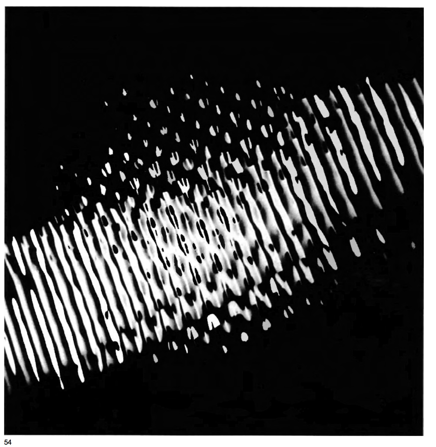
Figure 1-5. Cymatics Research - in "Cymatics:A Study of Wave Phenomena and Vibration" by Hans Jenny
2. Design Form + Fabricate "Orb"
I got way carried away with my original design. For some reason, perhaps the mechanism switch from electromagnets originally to speaker got me to change from a linear surface to a round orb-like form. I was interested in making these pebble-like forms, and then I thought I could wrap something around it to hide the electronics.
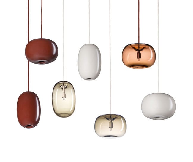
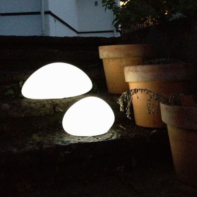
Figure 6-7. Pebble-like lamps
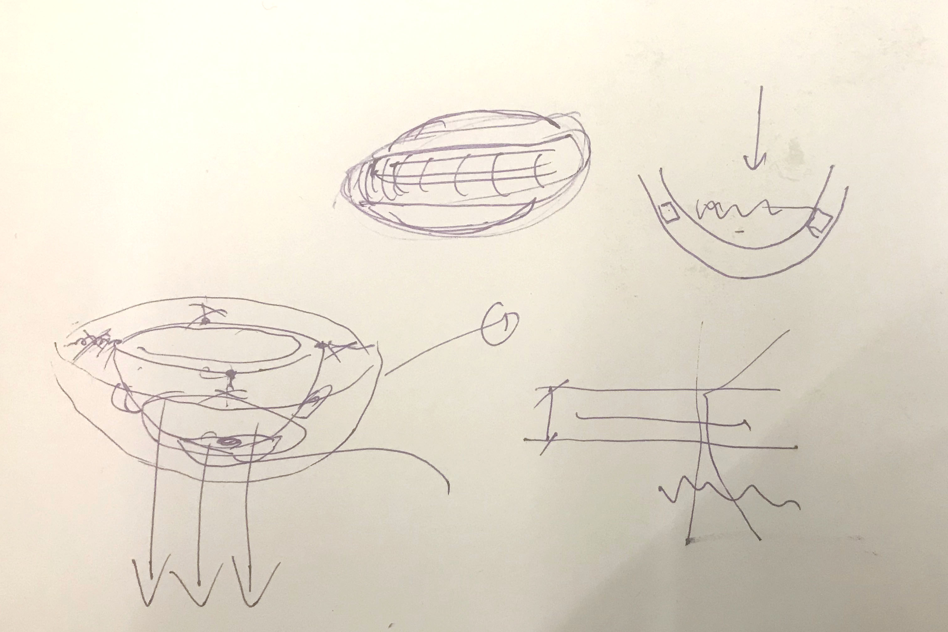
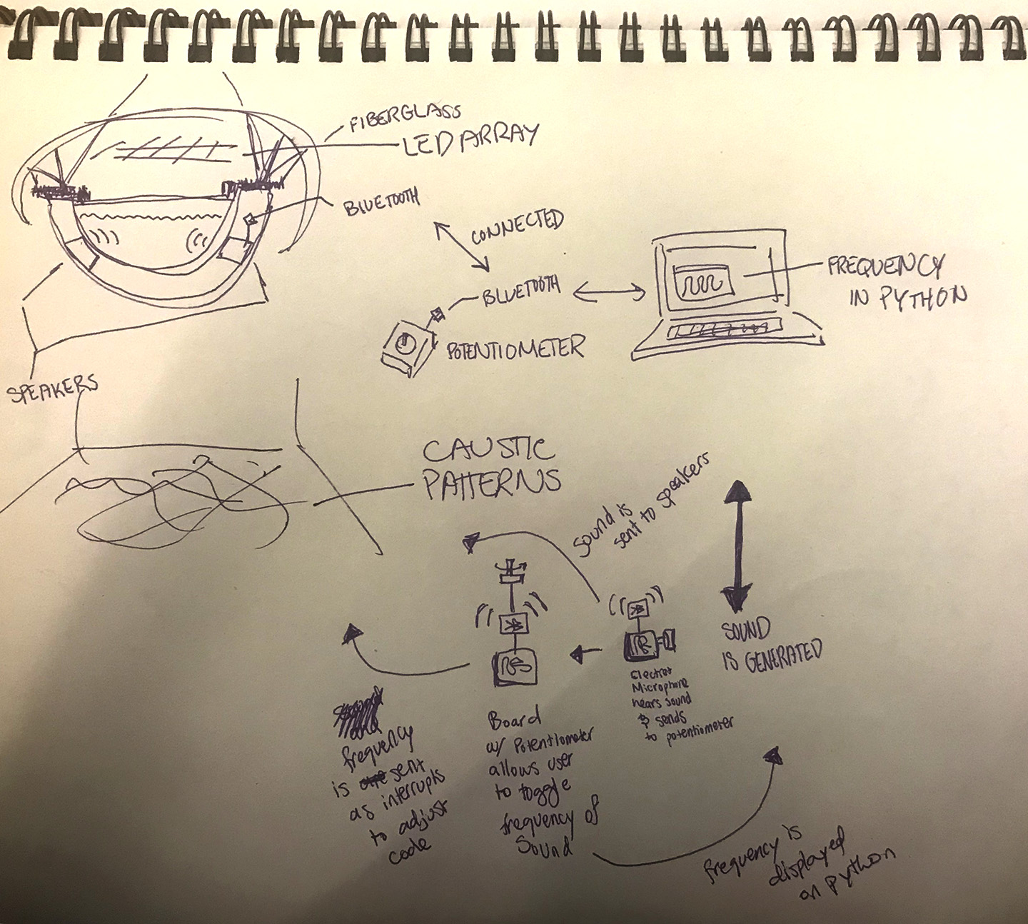
Figure 9-10. Sketch of plan showing mold within mold, speakers on the side (which I didn't end up testing, but would like to in further experimentation)
As I was designing my mill files and they turned out to take up a lot of time and material, I consulted with a friend who suggested I scale back, see if it works, and then go bigger. This advice was extremely wise and on point. Lugging around and doing everything at a much larger scale would have been unnecessarily difficult. I ended up sticking with this prototype version due to lack of time to create a bigger more formally rich piece, and I also think if I do modify the shape to continue with I would like to do a few more experiments and base the new shape on those results.
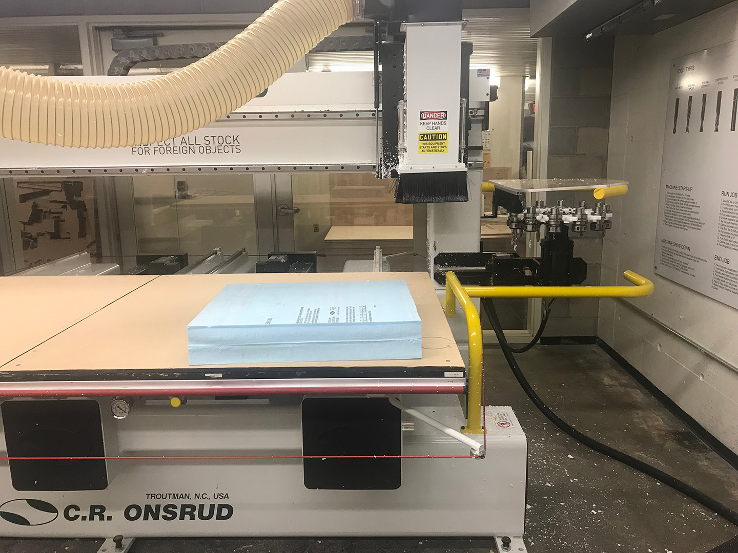
Figure 11. Milling Foam for Composites Week
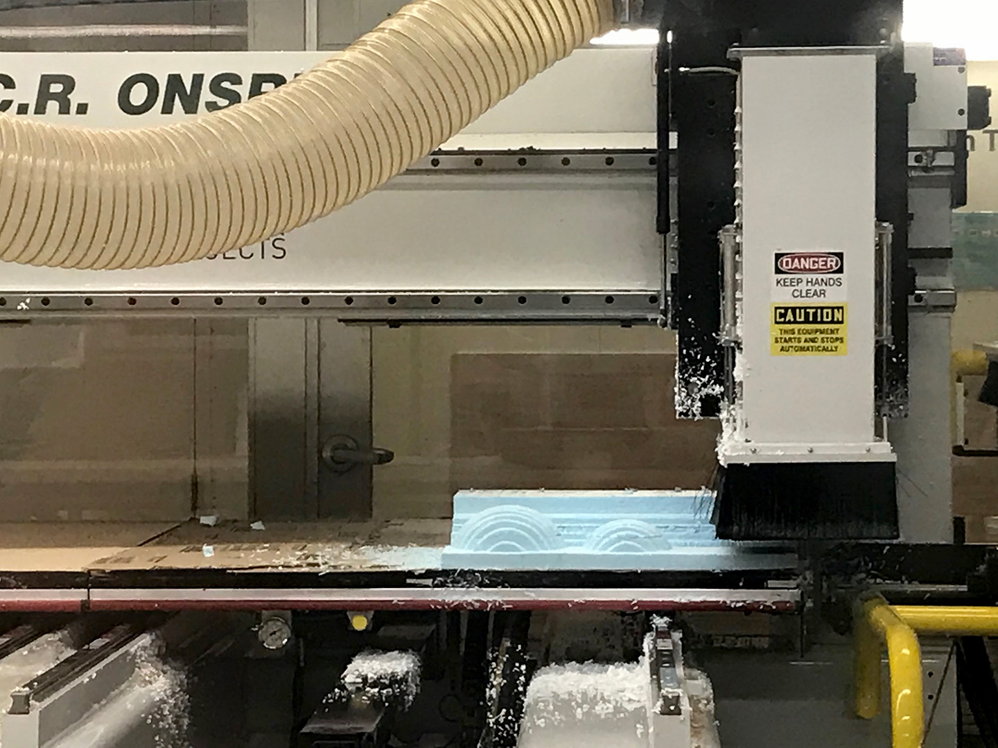
Figure 12. Two spheres, one slightly offset from the other to create a double shell/h6>
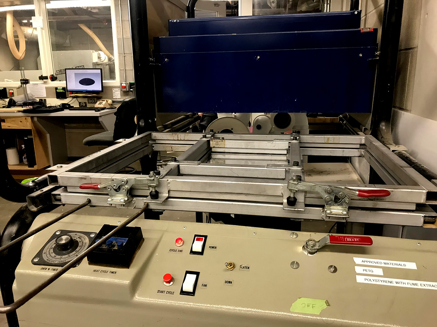
Figure 13. Going for a Vacuum Form
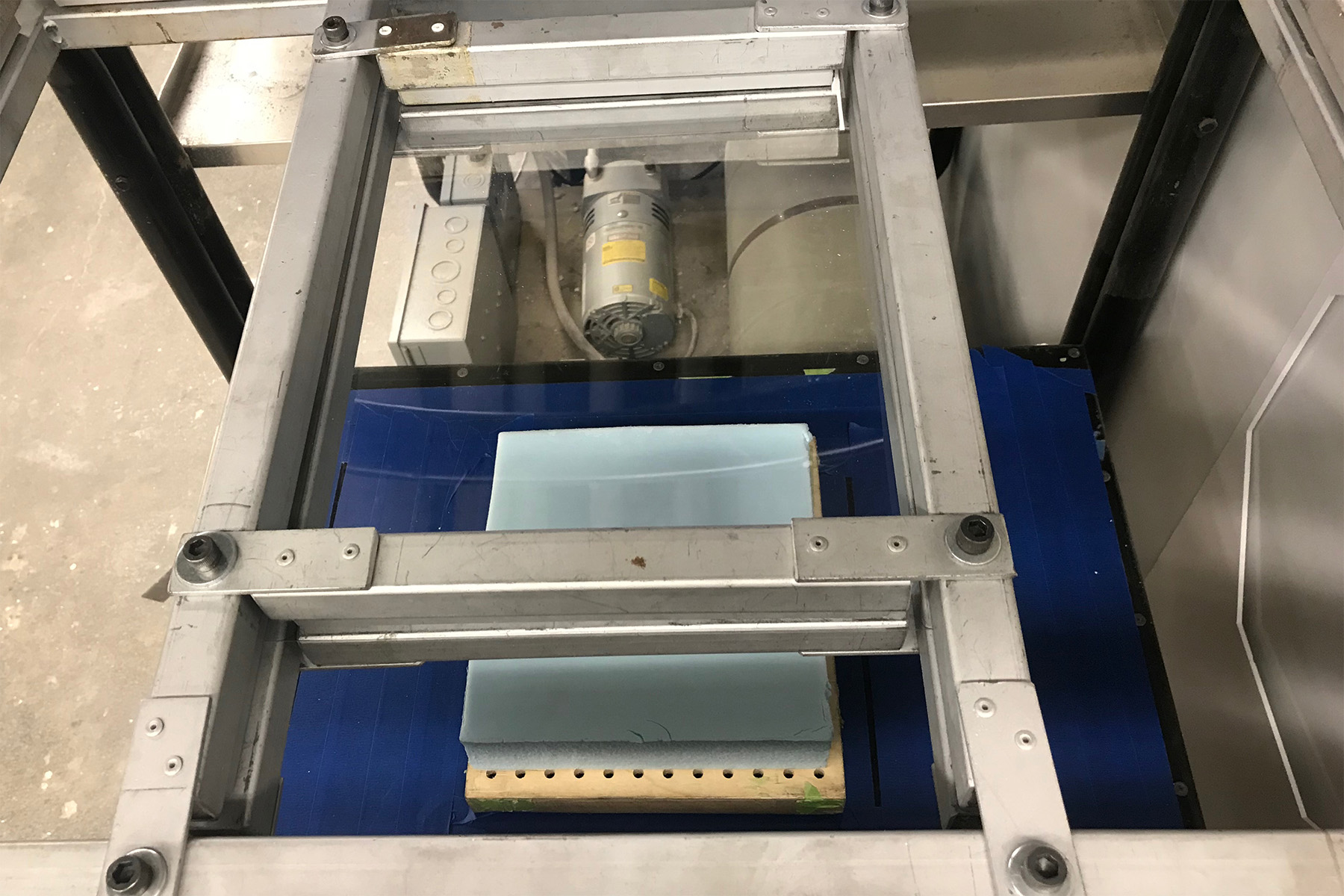
Figure 14. Setting up a test to see if the vacuum former can work with foam
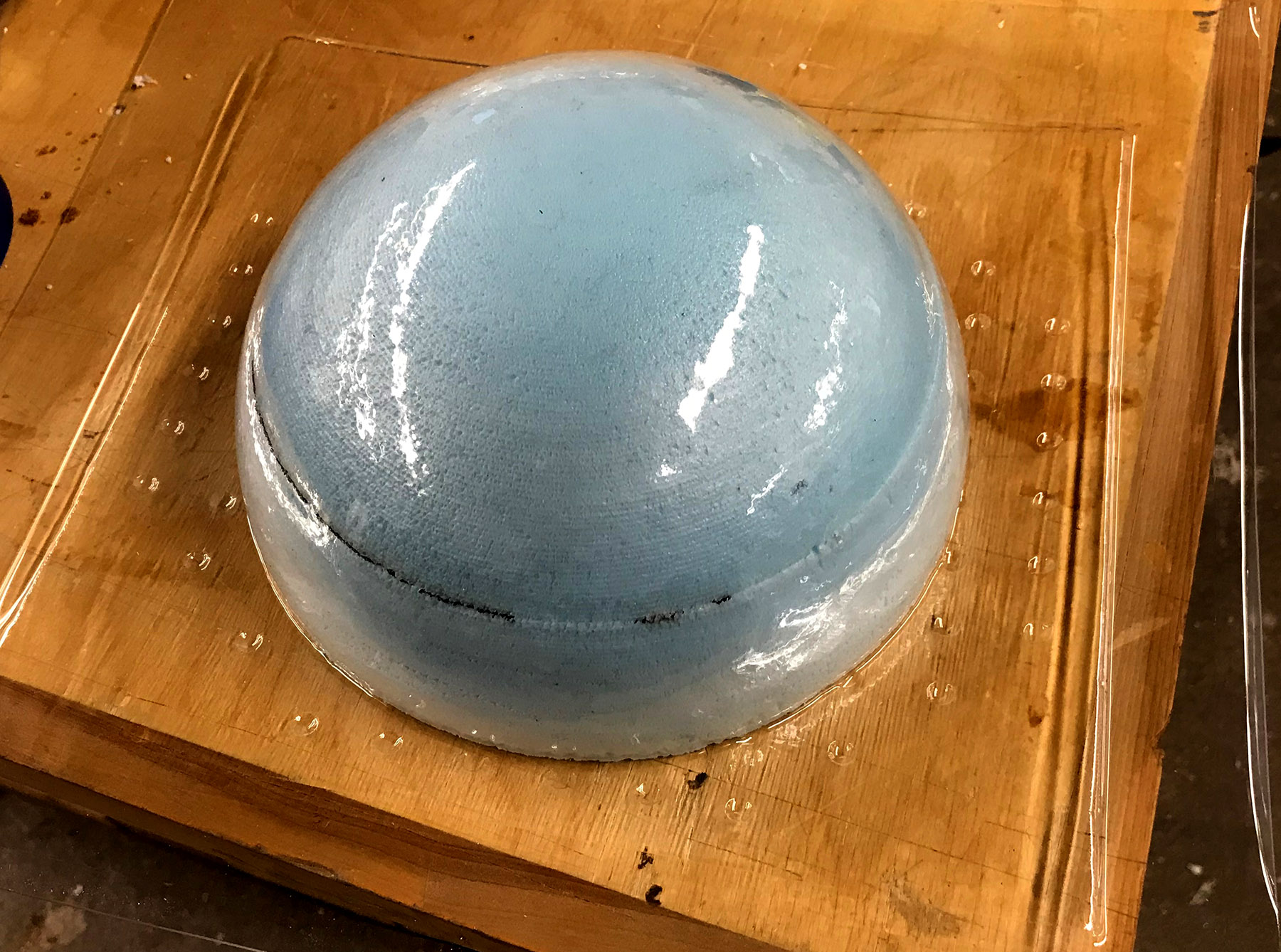
Figure 15. The test worked so I naively went for it and the Plastic (PETG) melted and stuck to the foam mold
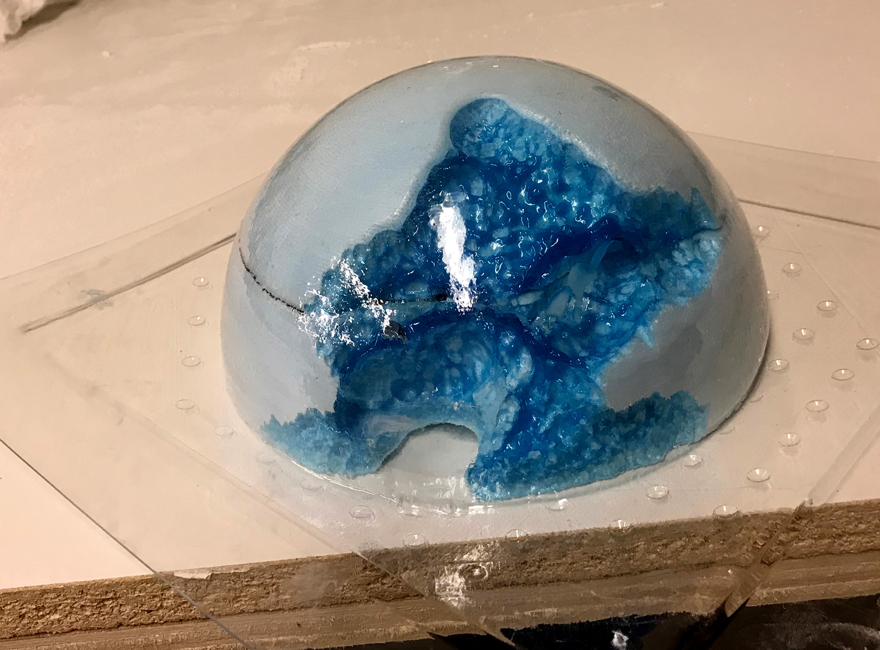
Figure 16. I discovered acetone works to disintegrate form! But I had to admit a loss of this mold unfortunately
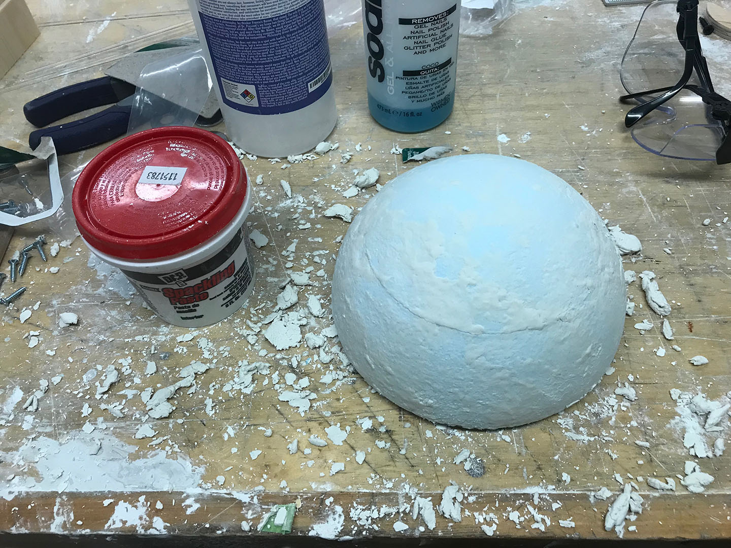
Figure 17. For the smaller mold I tried coating the foam with a thin layer of Spackle to seal the porosity
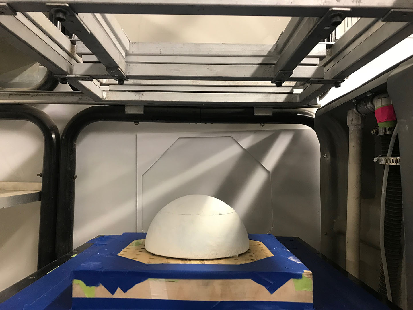
Figure 18. I waited half an hour for the Spackle to set then came back to set it in the Vacuum Former
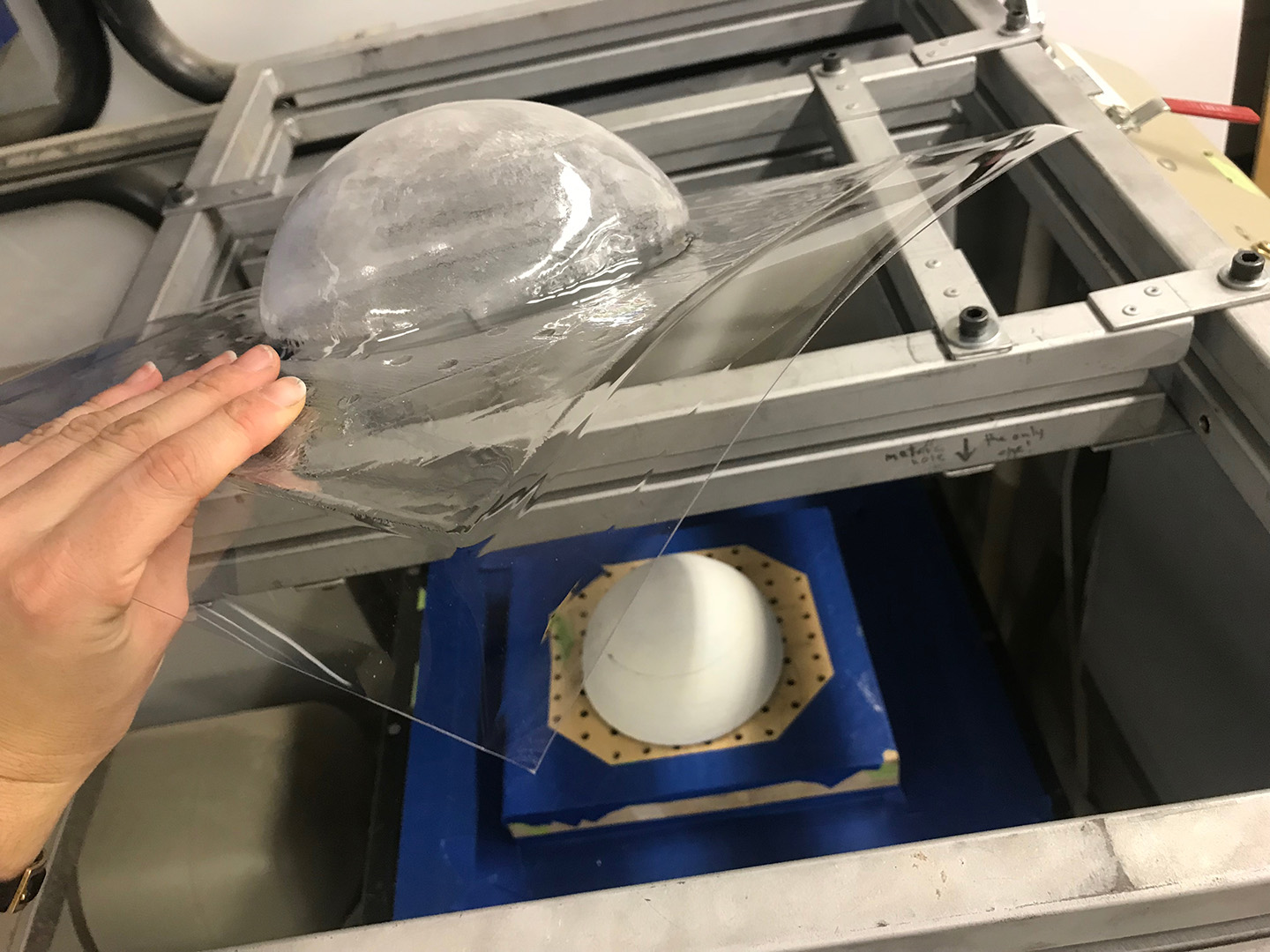
Figure 19. It worked perfectly! What a relief!
3. Test Speakers + Order SuperBright LEDs
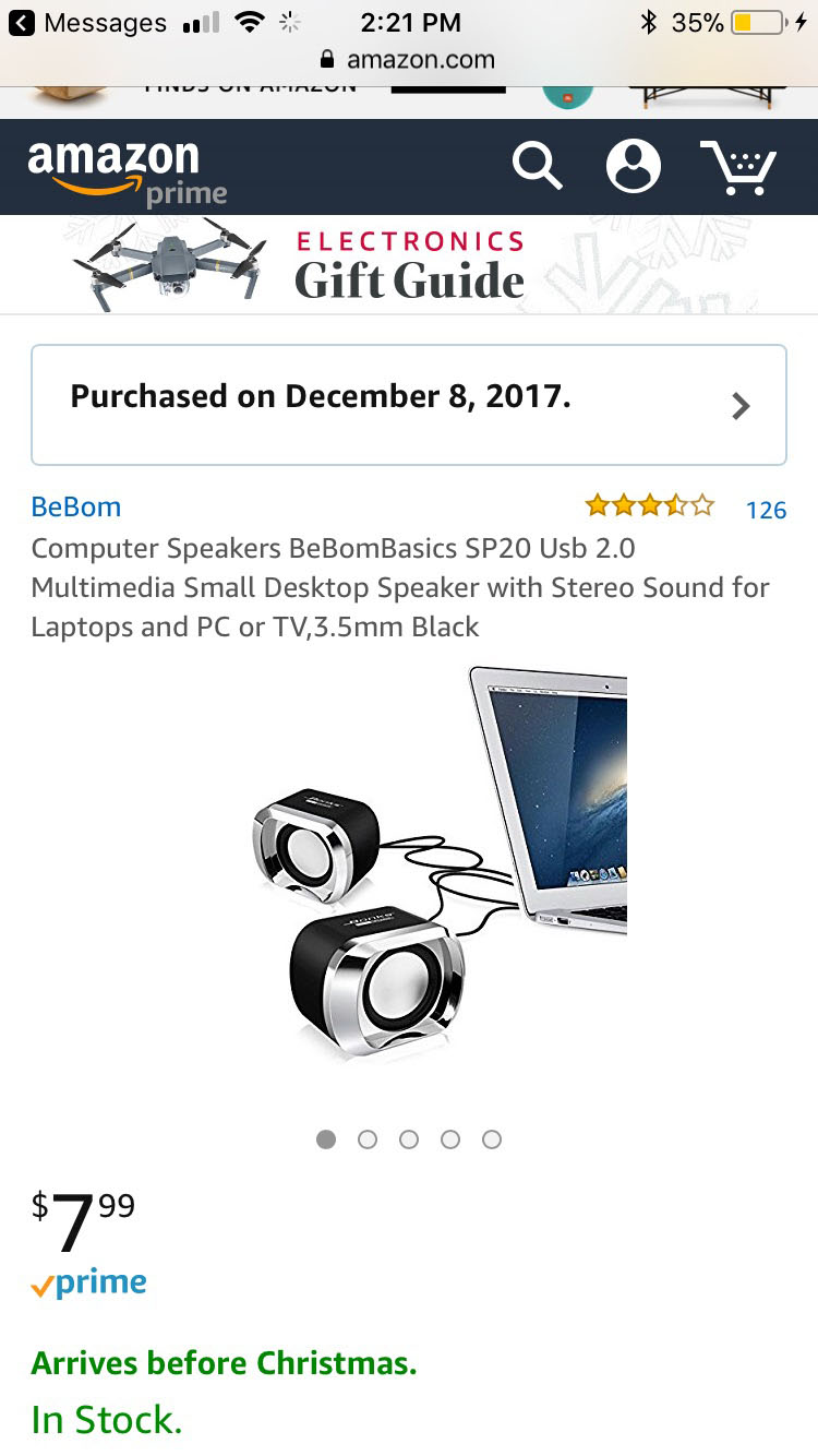
Figure 20. I ordered some cheap Speakers on Amazon, I wasn't sure exactly which vendors to seek a speaker part from, so I resorted to Amazon.
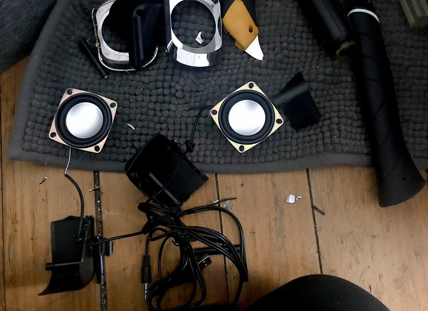
Figure 21. I was excited to see the contents as soon as they arrived. I smashed them with a hammer until I could pry the speakers out!
I brought them into the lab, and first tested to see if they even work.
Figure 22. They did!
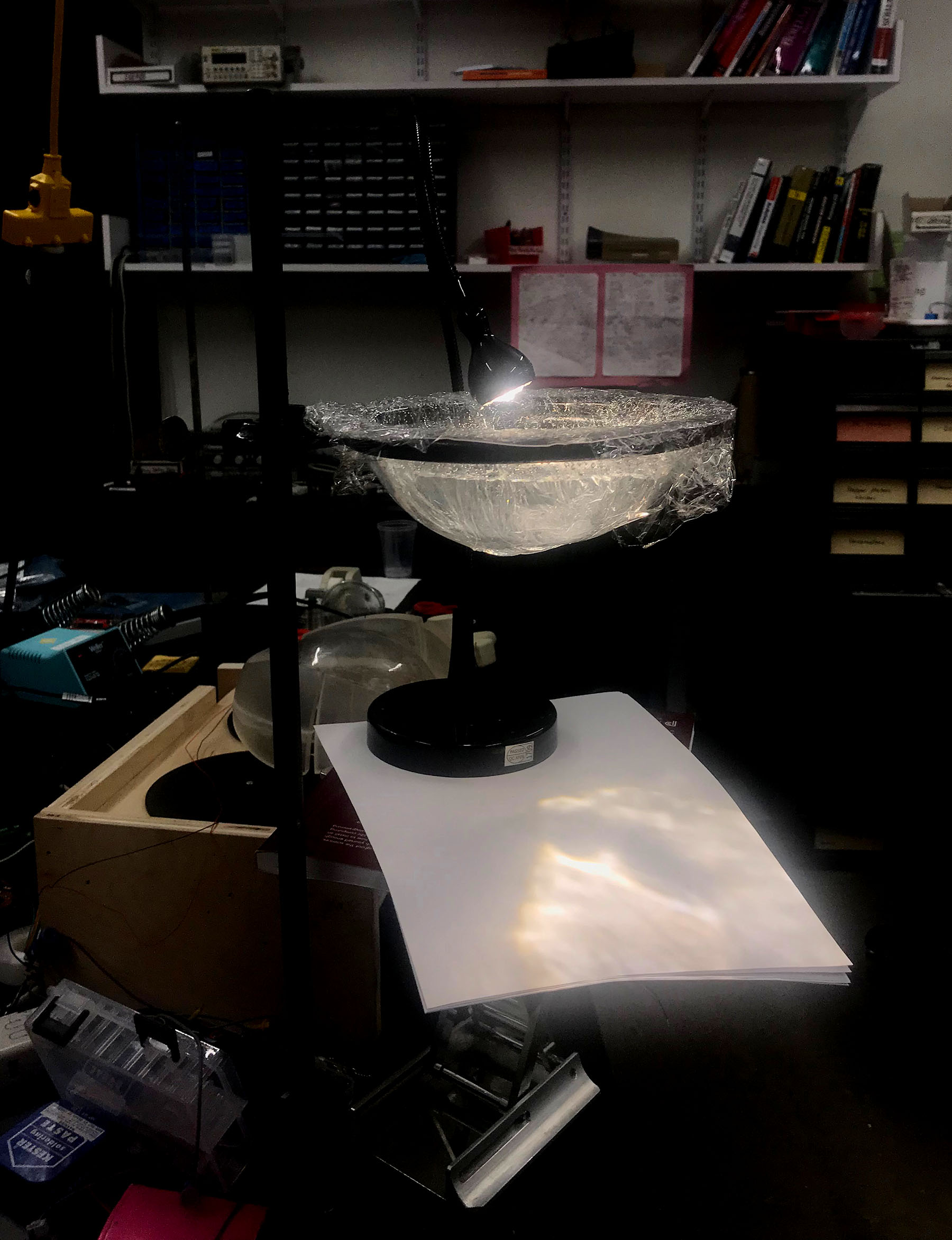
Then I wanted to test them in the water. I first tested them just on the bottom of the orb piece filled with water, but the orb was two thick of a plastic and there was hardly an effect. I decided to try direct contact between water and speaker. I laid up two layers of cellophane for quick waterproofing and placed the speakers underneath.
Figure 23. Speakers with Cellophane and Water Layer
It seemed this was not doing so much either so I cut a hole at the bottom of the orb and then put the speaker on the bottom, again using the cellophane for waterproofing.
Figure 24. This time I got some really nice effects!
At first I was just playing a Tycho soundtrack because it has a nice variation of frequencies. Next I tried this online Tone Generator so I could quickly see the effects of different frequencies so I could approximate a range for the code.
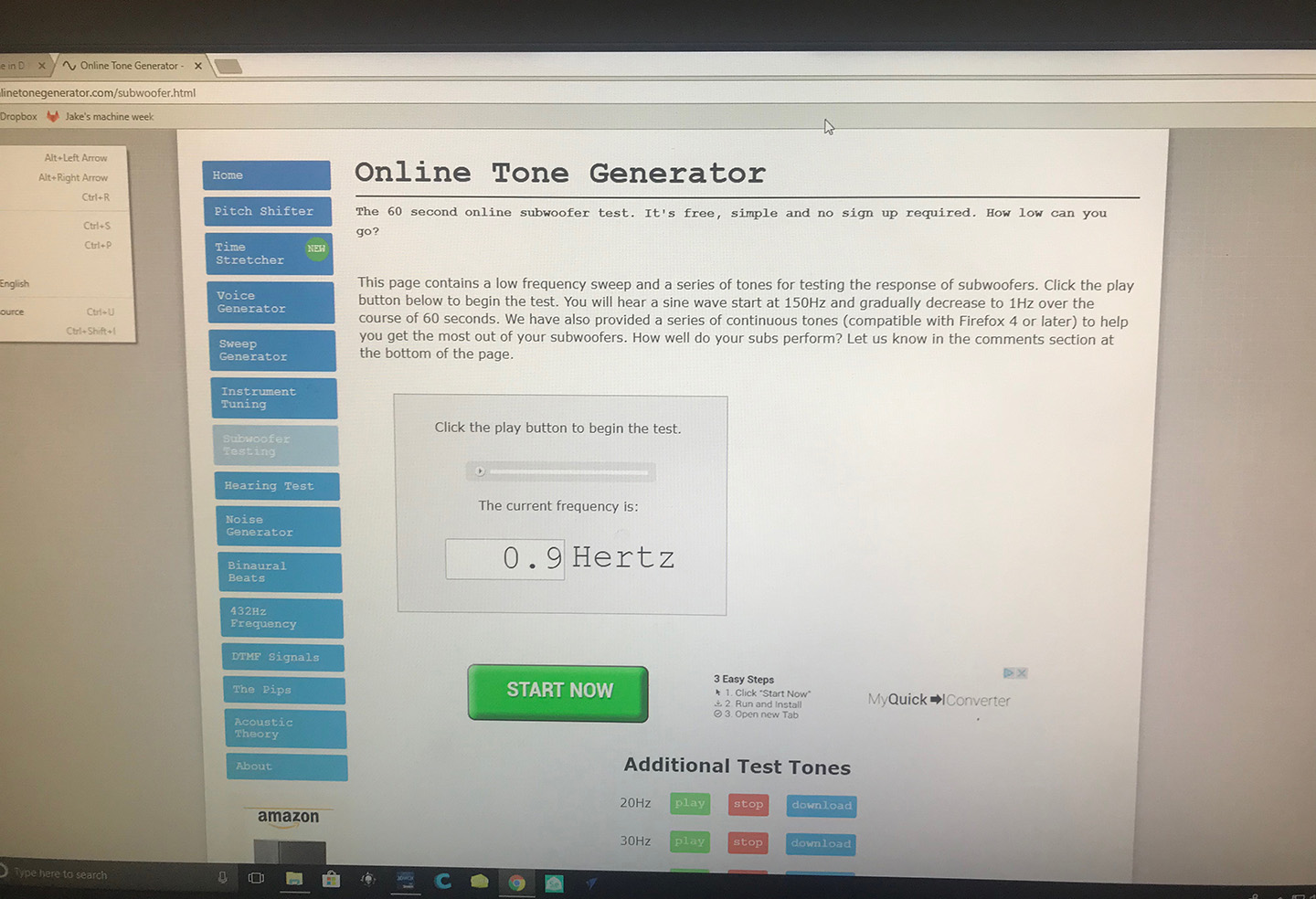
Figure 25. Online Tone Generator
During class I asked Neil for a suggestion on which LEDs to use for the lamp, he suggested these SuperBright LEDs from SuperBrightLEDs.com. He also spoke about the spiral workflow strategy to always come back to a working, wholistic piece. I think I definitely tried to do this, but at some point in the proecess stress and anxiety kept me from going back to testing and assembling and simply looking forward. I do deeply regret this because while I put parts together and had wholistic components, I think had I put everything together more early on I would have had more time to troubleshoot directly and approach issues more early in the process.
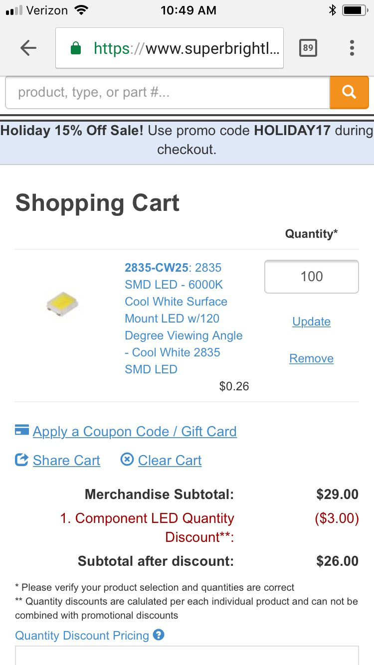
Figure 26. I wound up getting only 25, and I chose Pure White in the end
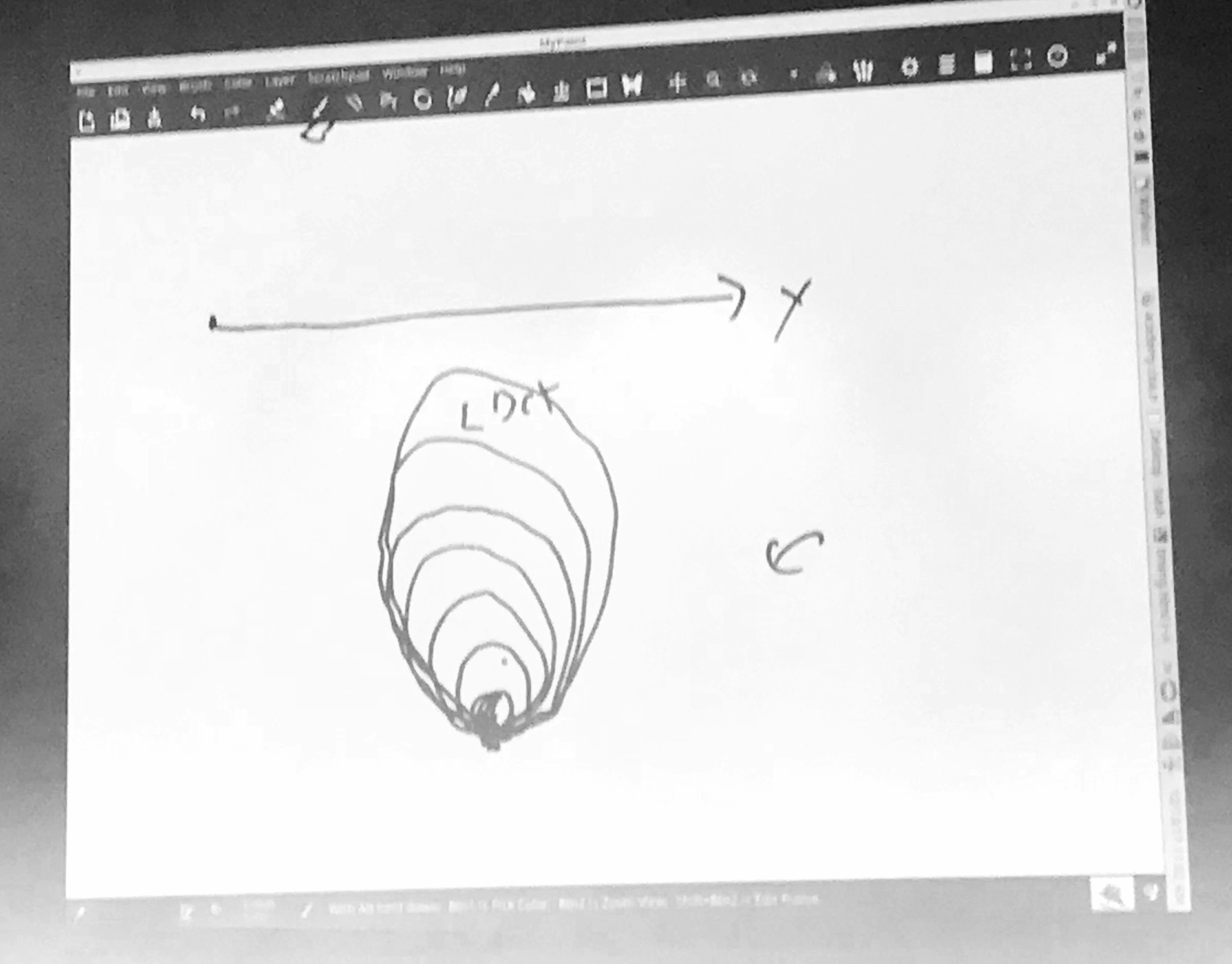
Figure 27. Neil's spiral workflow diagram
I joked later in the lab that my spiral was growing in the opposite direction as I kept scaling back my ideas upon realizations that I didn't have enough time to achieve everything I wanted (nor was it necessary to prove the concept).
4. Design Master Controller
I worked closely with Dan Chen's board from his tutorial on Bluetooth Modules
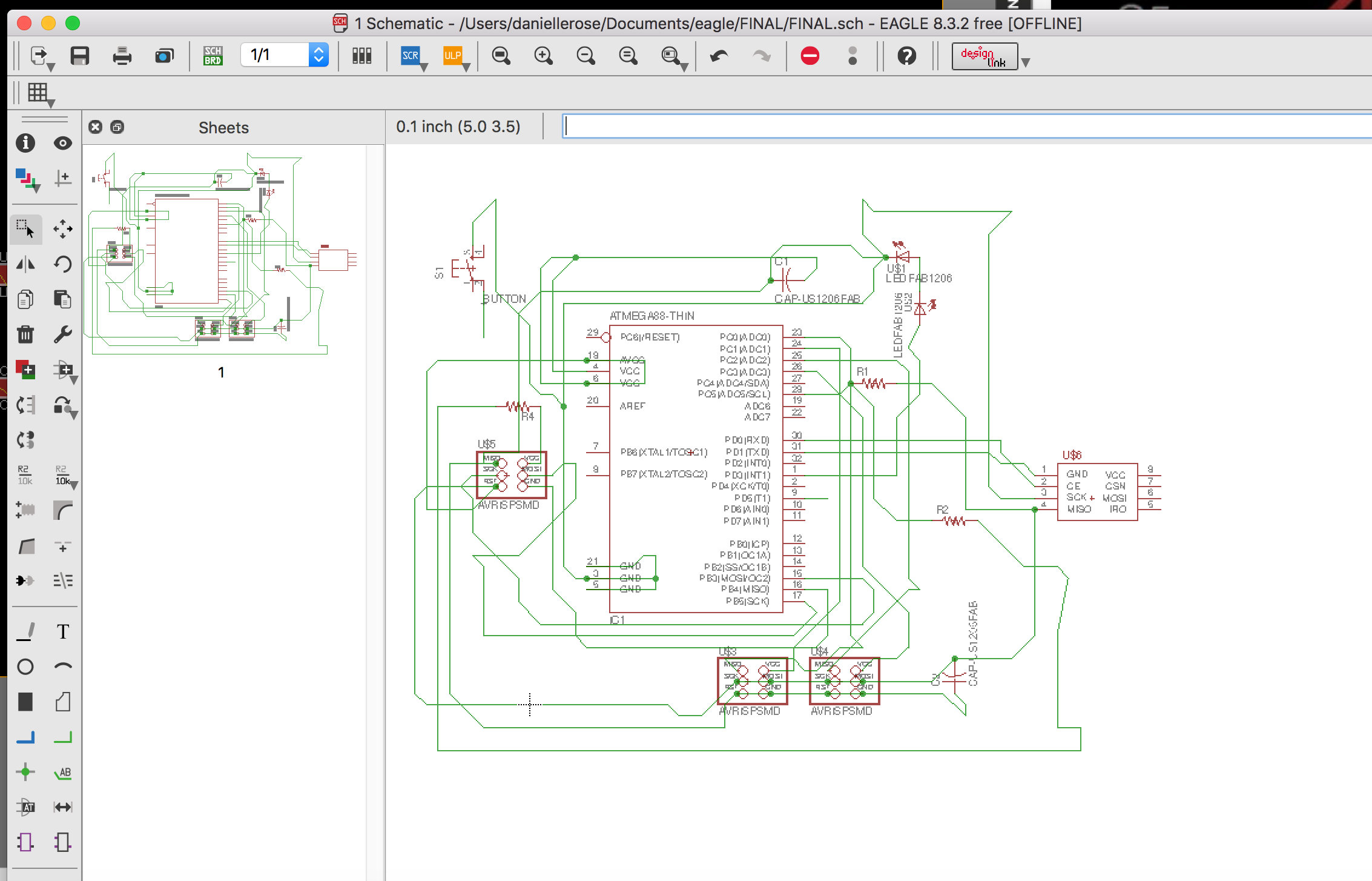
Figure 28. Figuring out Dan's logic, and adding on a button
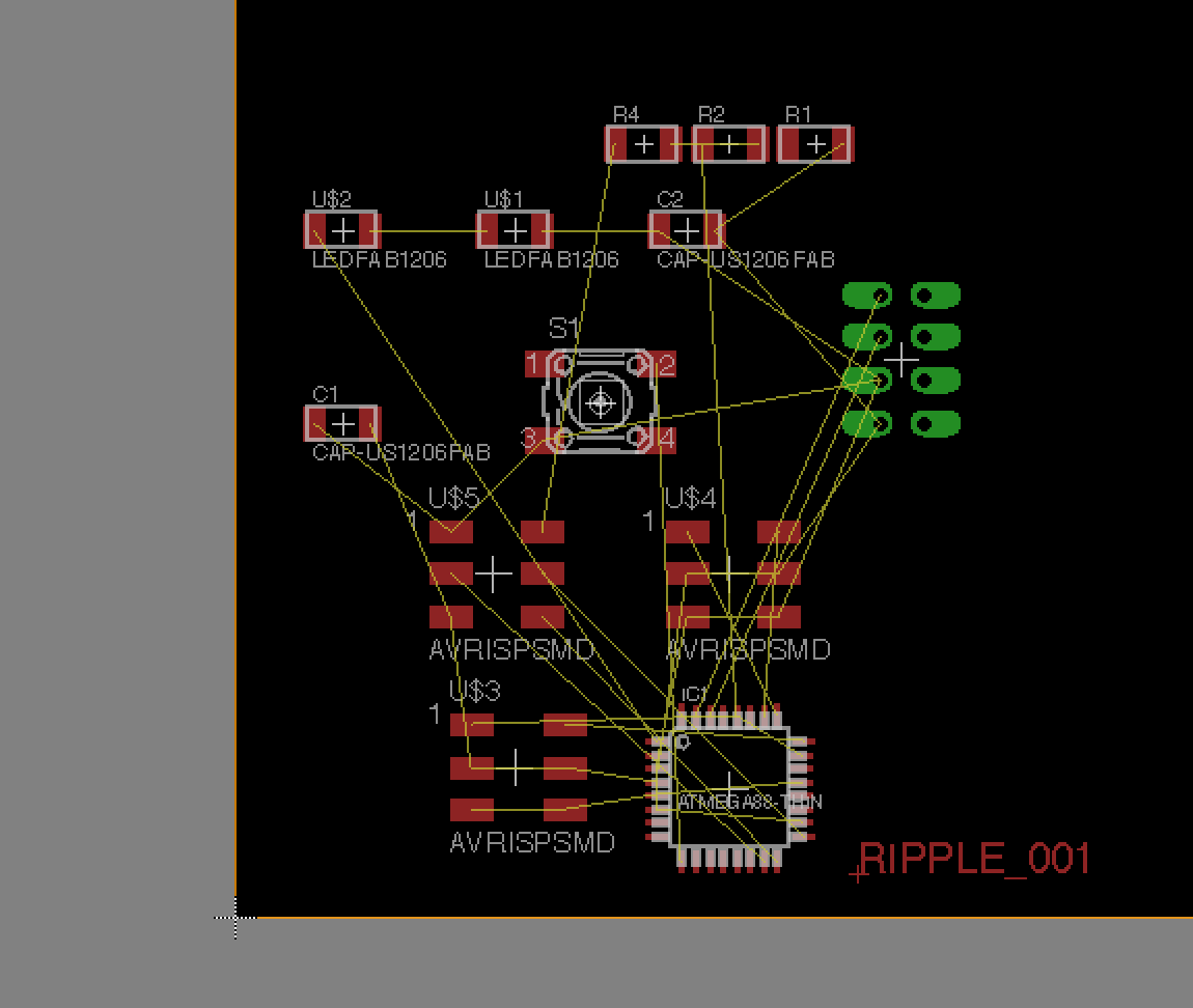
Figure 29. Adapting to fit two potentiometers instead of a potentiometer and a servo
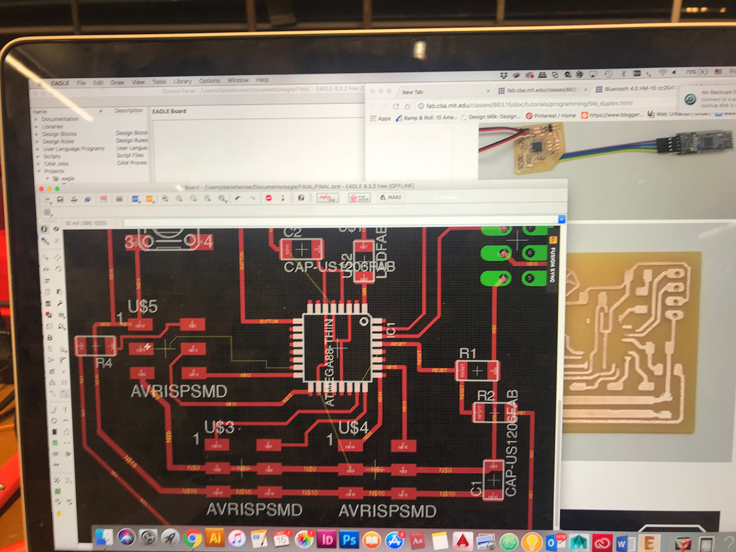
Figure 30. Cross comparison with Dan's board as I marvel at how efficient it is.
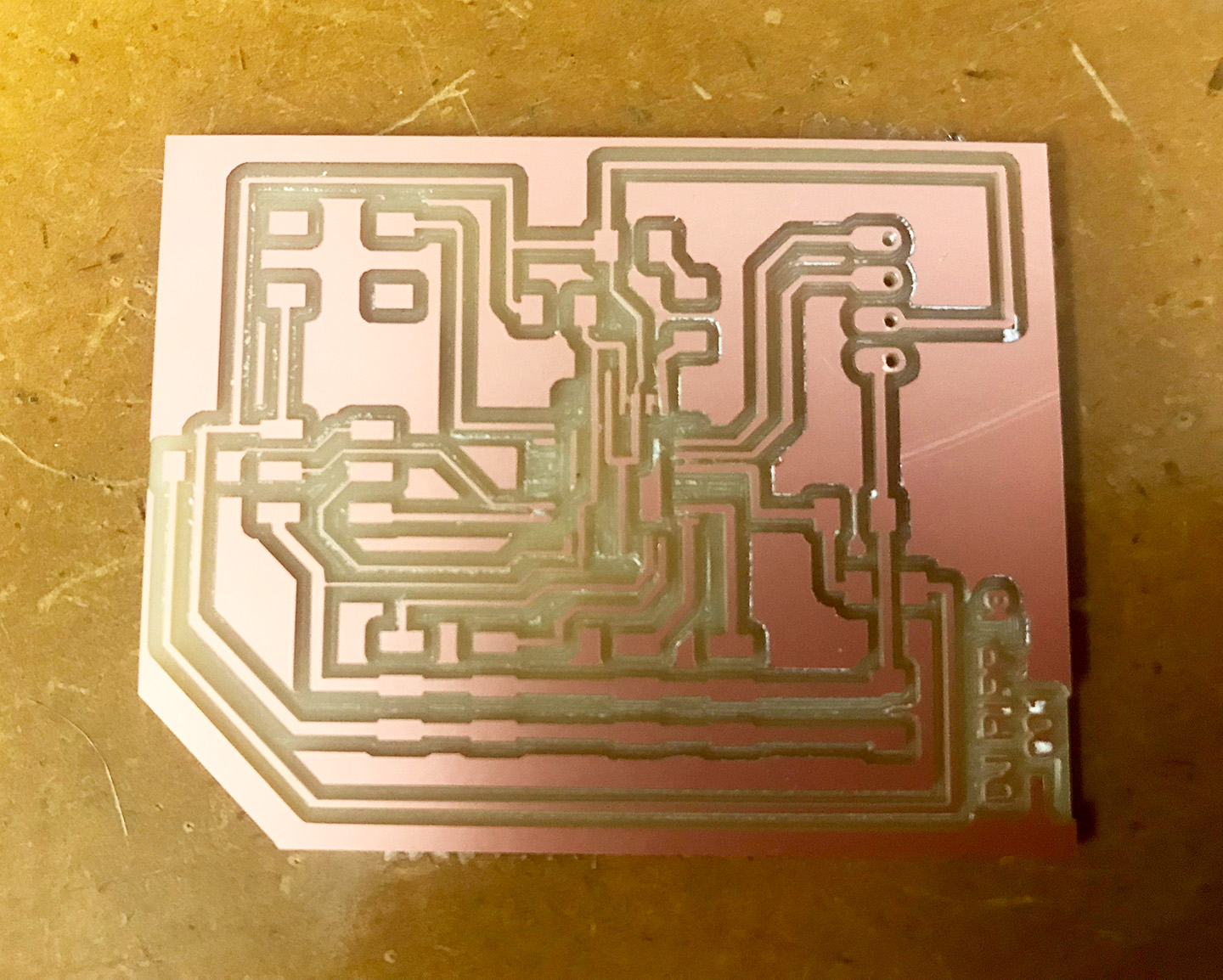
Figure 28. My attempt at stuffing everything in by alternating thickness in the wire proved faulty, especially for the very thin "6" width traces. I believe these were a point of failure.
5. Solder and Program
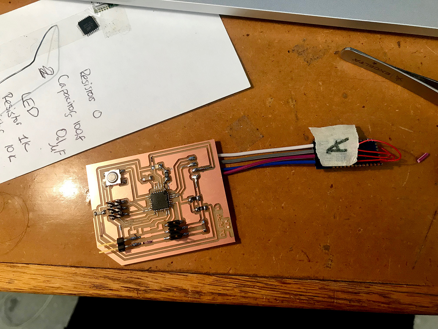
Figure 29. Nonetheless I soldered the components and tested it.
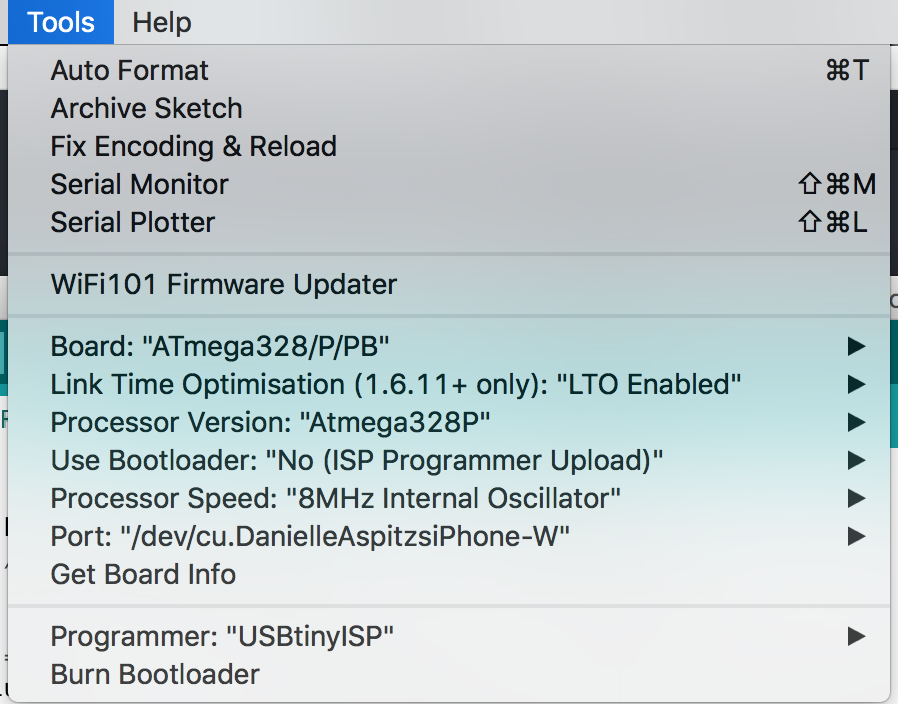
Figure 30. I had to read another of Dan's tutorials to find the appropriate libraries necessary to get the ATMEGA328p boards to show up.
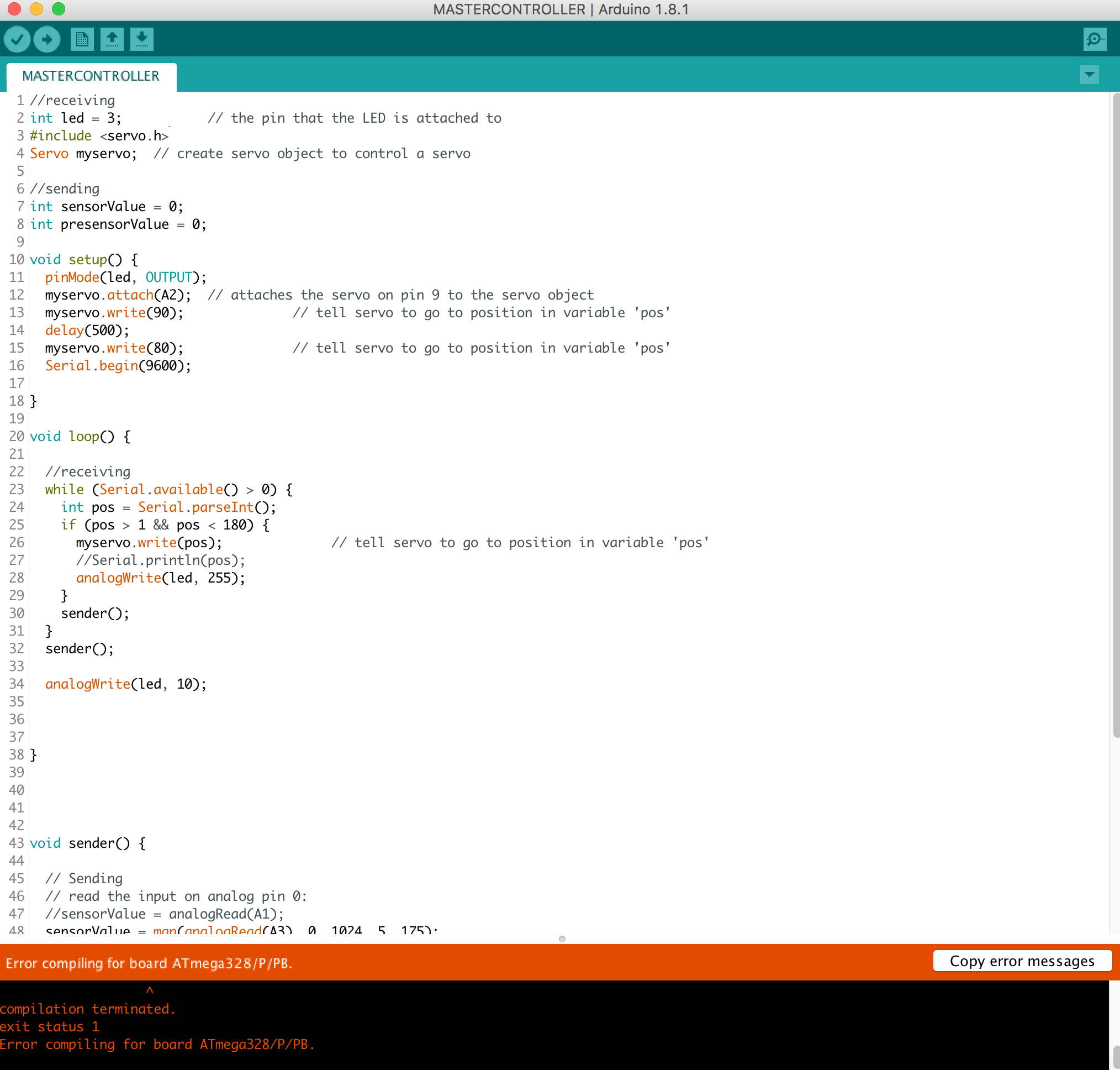
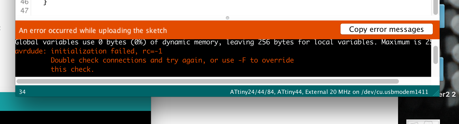
Figure 32. I kept getting this error message "rc-1" wich Joe Negri, one of the TAs helped me decipher was an issue with the board.
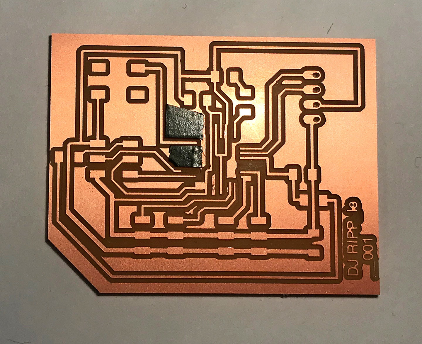
Figure 33. I was concerned the traces were too thin in my board so I decided to start over. I re-milled the board with thicker traces and only an offset of 3 passes (rather than 4) in mods because some were quite close to one another. Upon consulting with Joe again, he had concerns about the big pads of copper shorting all the unused pins of the mega. So we chipped away some parts and used Electrical tape for the rest.
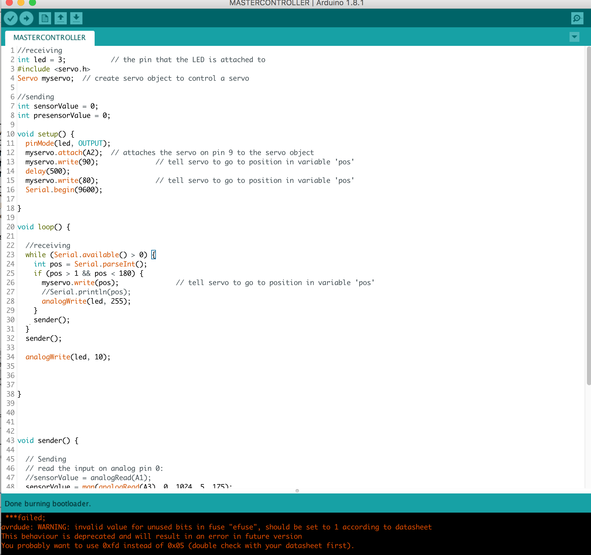
Figure 34. I was finally able to burn the bootloader! It worked! Hooray!!.
6. Fabricate Knobs
It was late at night when I told Dixon about my project and at some point he said it would be so cool if the knobs were just giant discs like a turntable.
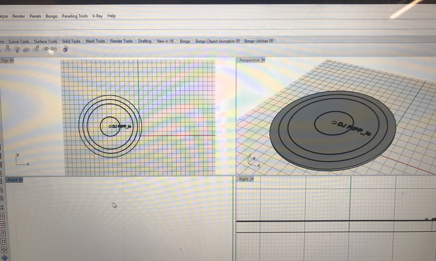
Figure 35. In the excitement I quickly designed a 3mm thick disc to print.
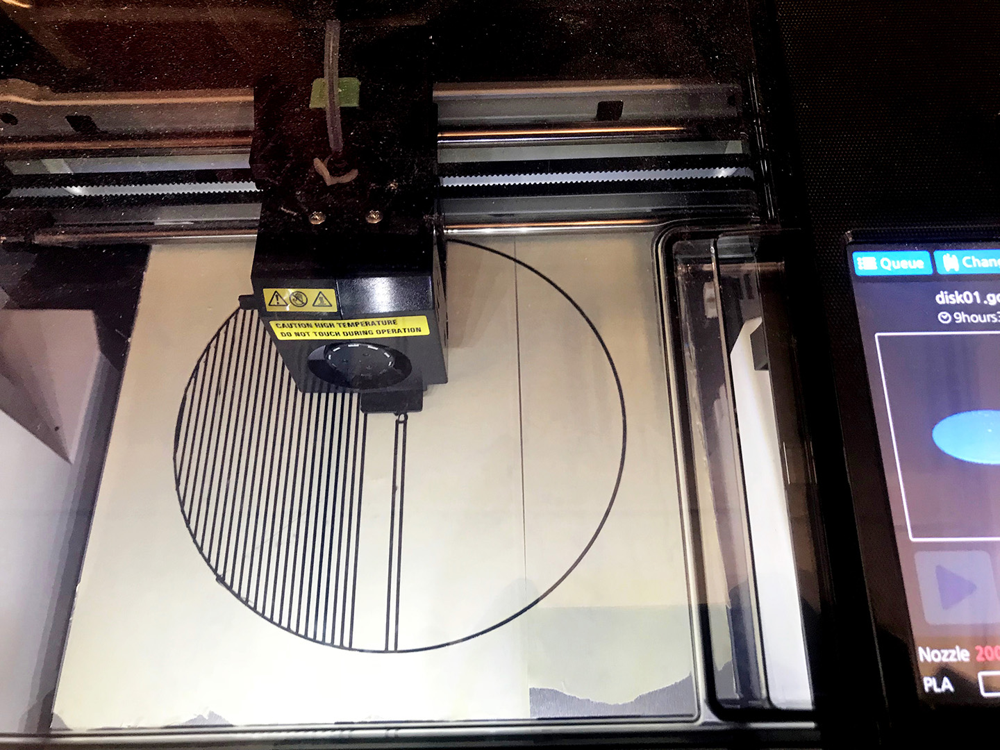
Figure 36. At first I tried printing with the default settings which would have taken 9 hours! I consulted with Julia Ebert who had been doing a lot of 3D printing for her army of robots. She suggested I take off the raft as it was a completely flat thing - no need for a raft, and that I create less density inside. This brought the print down to only 4 hours!
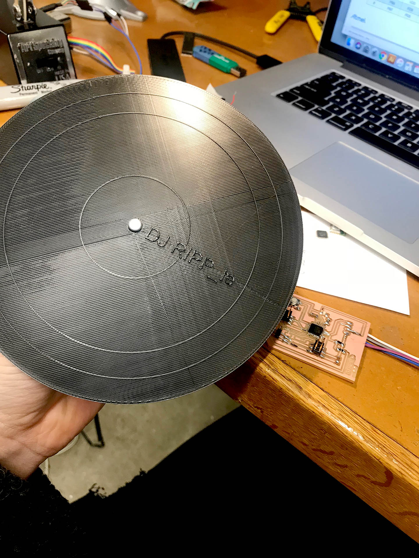
Figure 35. It came out quite nice.
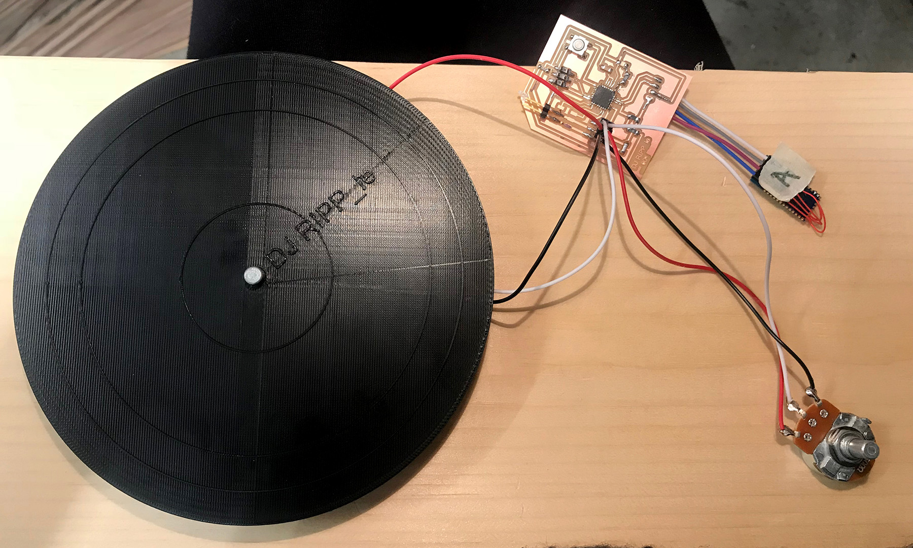
Figure 36. It needed a few passes with the round file, but otherwise the fir was very snug and the mechanism felt nice.
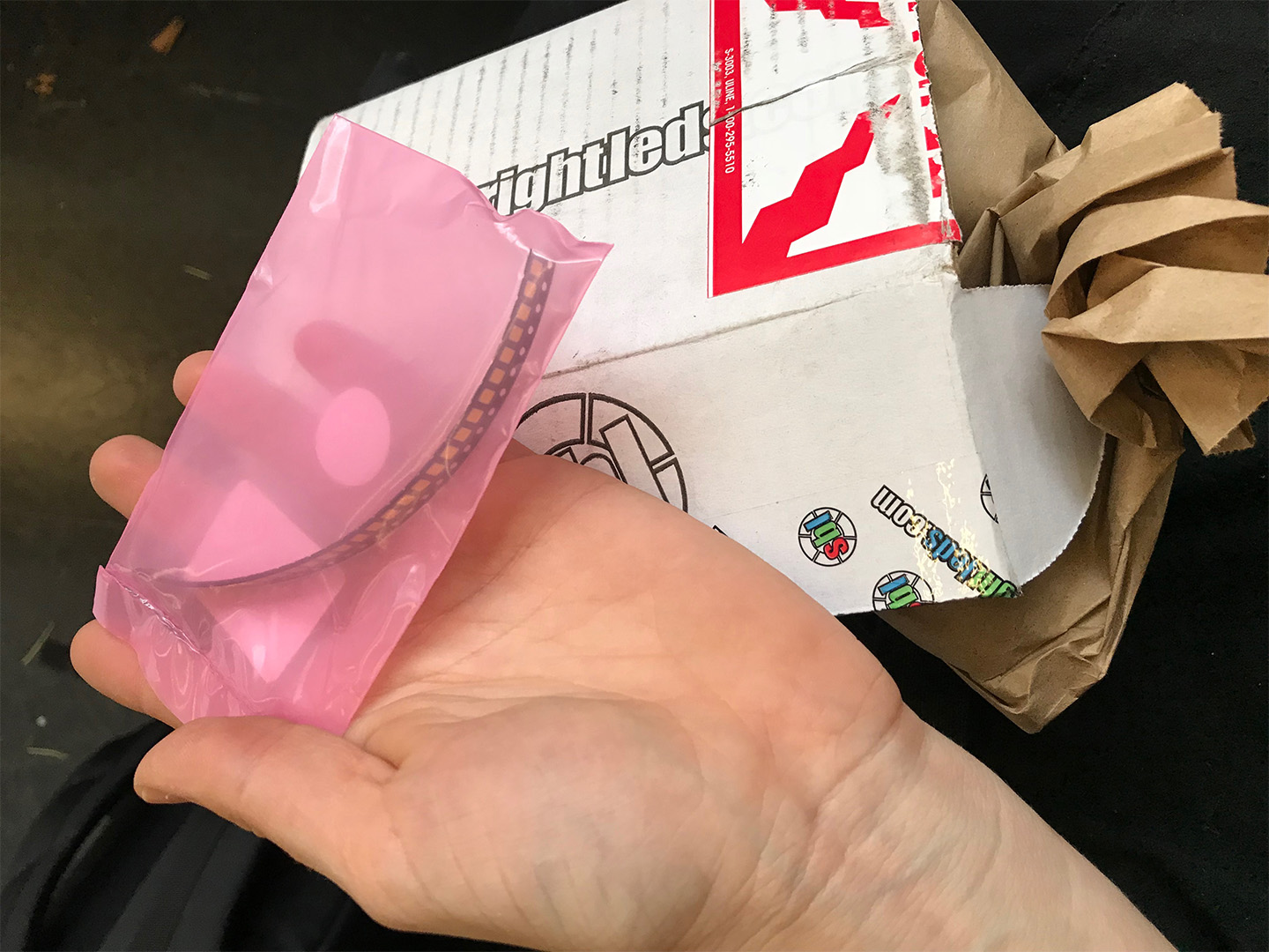
Figure 37. Also my superbright LEDs arrived!! Yay!
These were indeed SUPER bright. I fetl blinded every time I tried to test them or show someone.
7. Design + Fabricate Slave Board
This board took me a long time to design this board. I was essentially still using Dan's components and layout as the backbone and to ensure Bluetooth compatability, but I was adding in the Speaker board as one output and a SuperBright LED as the second output.
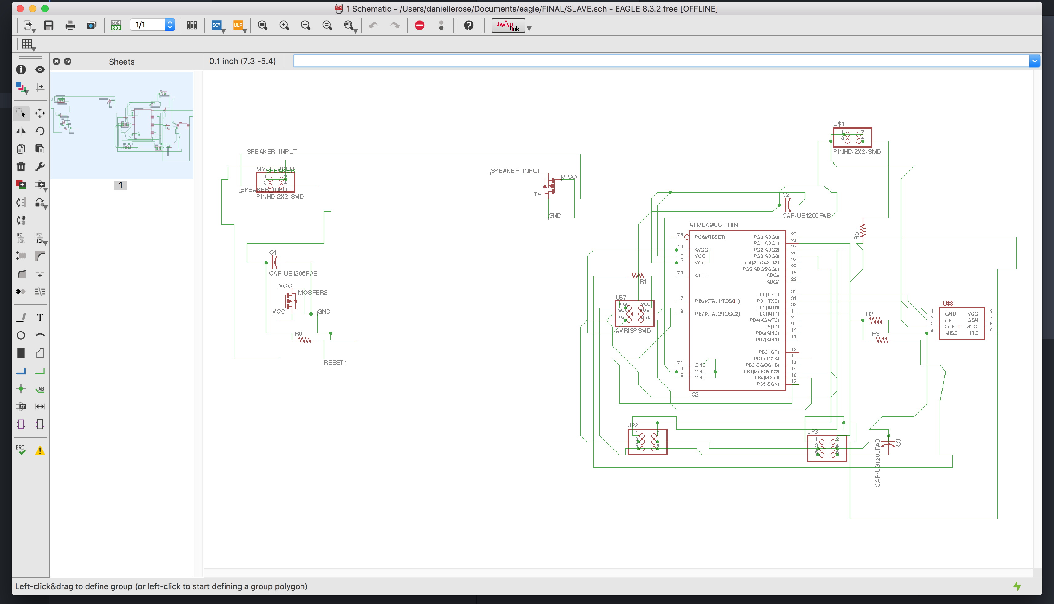
Figure 37.5. It took me a really long time to understand what was happening in the Speaker Board, I wish I could have revisted this lecture. Even though I made my own I had a hard time distinguishing between the Mosfet and the Regulator because the components look the same. I also didn't quite understand how the Mosfet was working, and I didn't remember the speaker had had a 9V charge rather than 5 until much later which then demystified the regulator. In any case my work in routing these components would have been a lot easier had I understood this earlier and I did need a lot of jumper cables to fix the mistakes I had made.
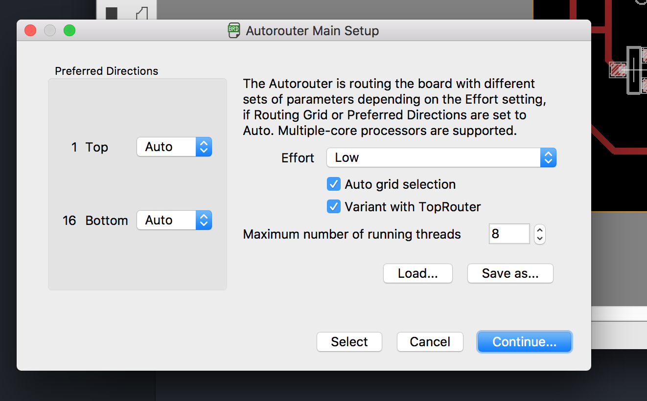
Figure 38. It was at this time that a friend showed me how to use the AutoRouter. I thought it was quite helpful to get an idea of the efficiency.
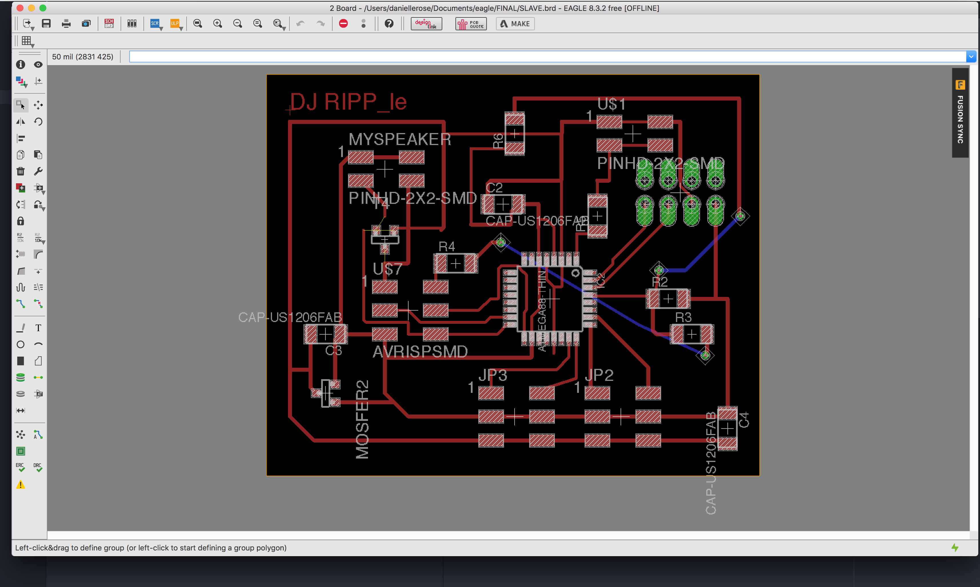
Figure 39. As much as I tried I could not fit all the components on without a few vias. I got the number down to two wires and in photoshop edited the file to include holes I could drill with a Dremel and a tiny bit.
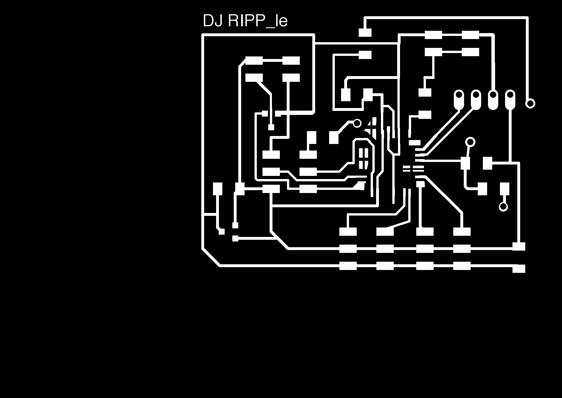
Figure 40. I edited a number of things, following Dan's advice I deleted unused pads and extended used ones. I created the holes for the vias. I deleted bits of paths that seemed to close. Lastly I cut up the copper parts under the ATMEGA 328p so I could more easily chip of these sections and avoid shorting any pins.
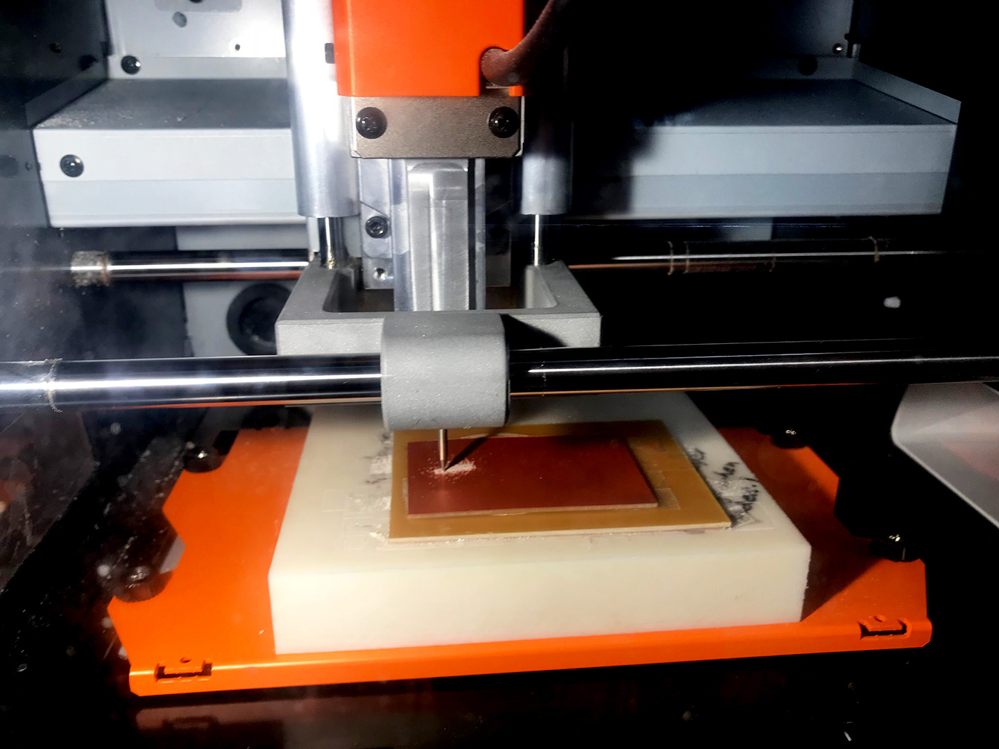
Figure 41. In this iteration I tried to use the 0.10 endmill to see if it could get the finer traces.
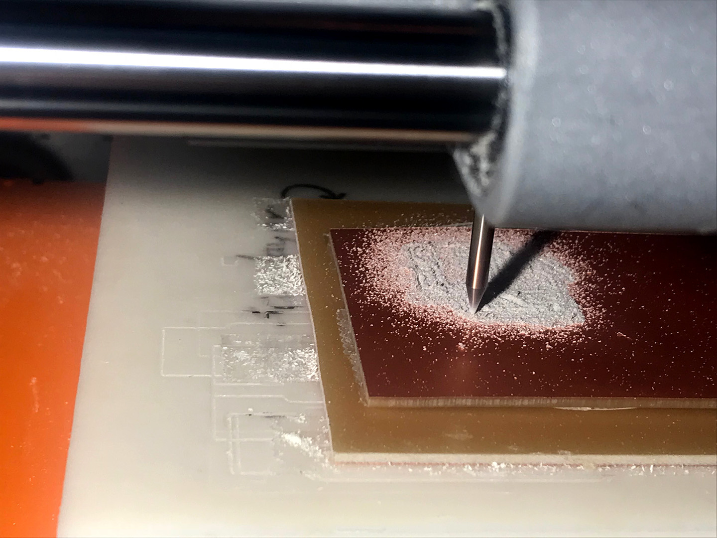
Figure 42. The 0.10 endmill broke so I remilled it with a 1/64th bit, recalling what Neil had said about doing one or two offsets with the 1/64th and then putting in the 1/10th to finish the job. I will try this next time.
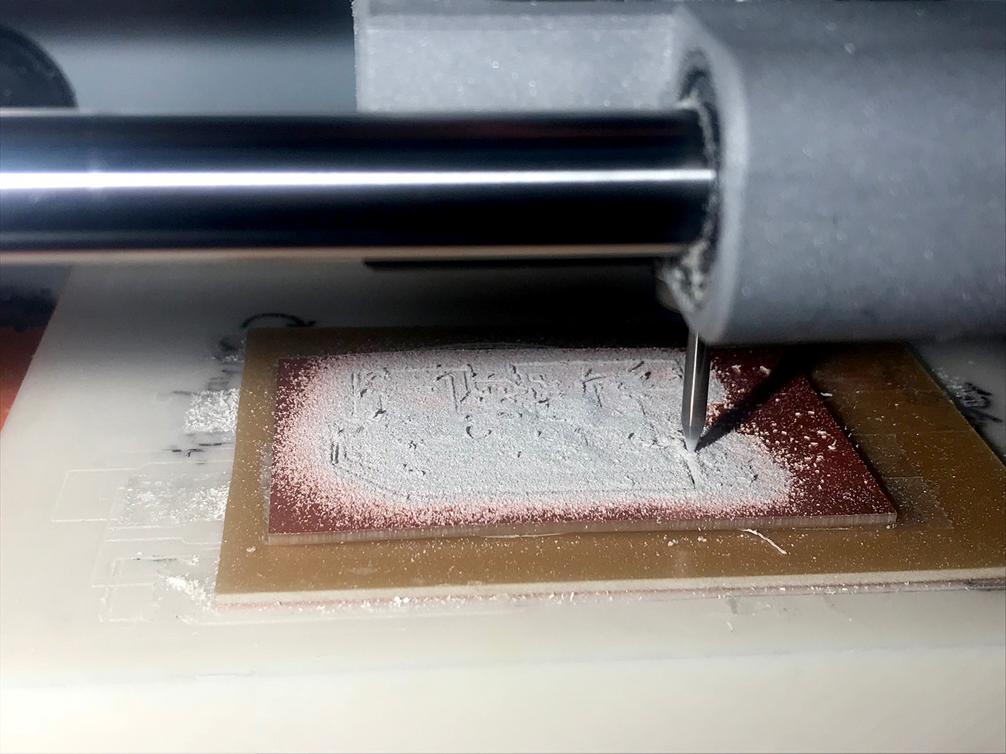

Figure 45. I quickly designed a tiny LED board, accidently forgetting to connect the via holes to the LED pads. I also had to make a second one, because the first one got eaten by the vacuum!
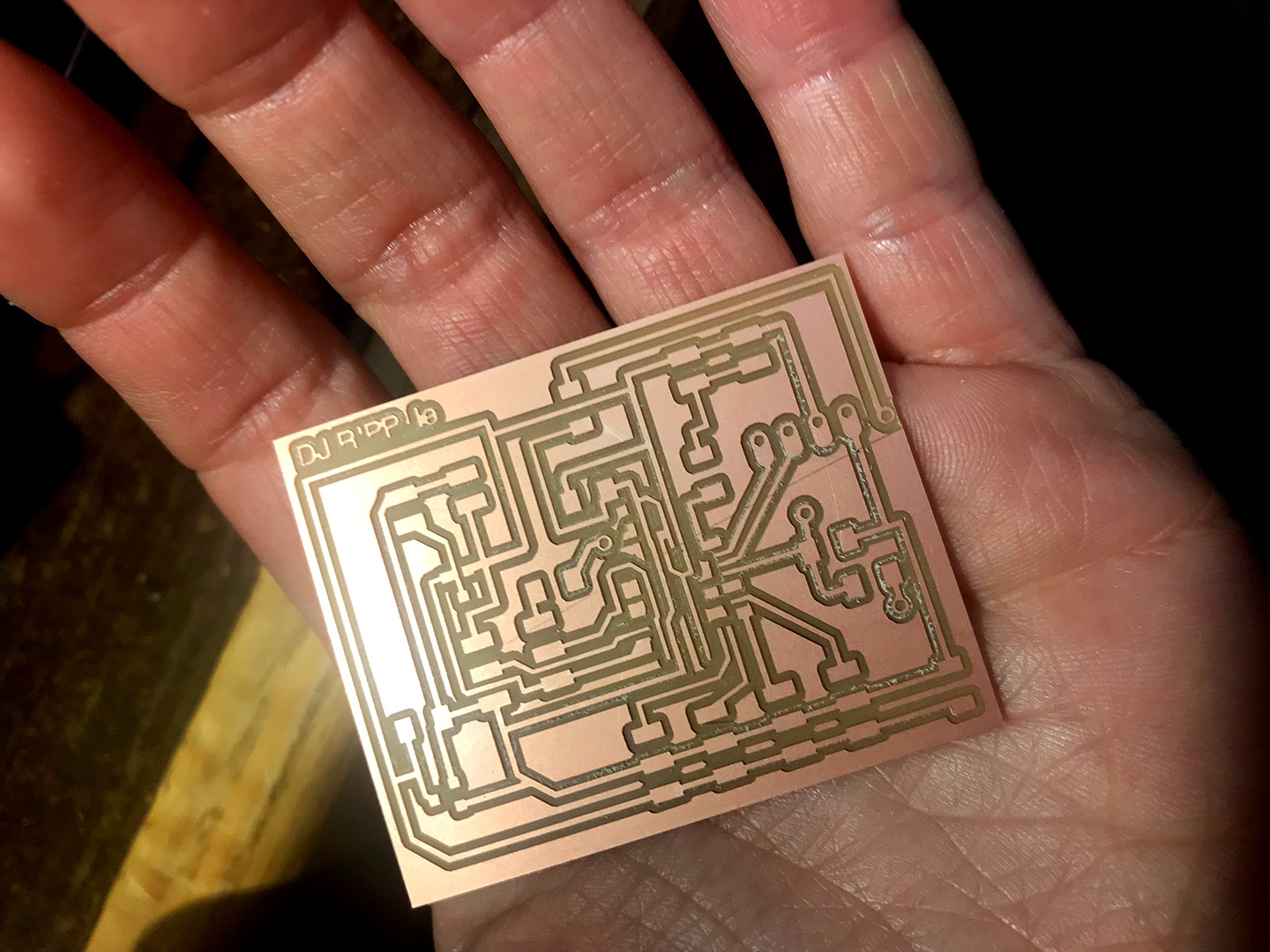
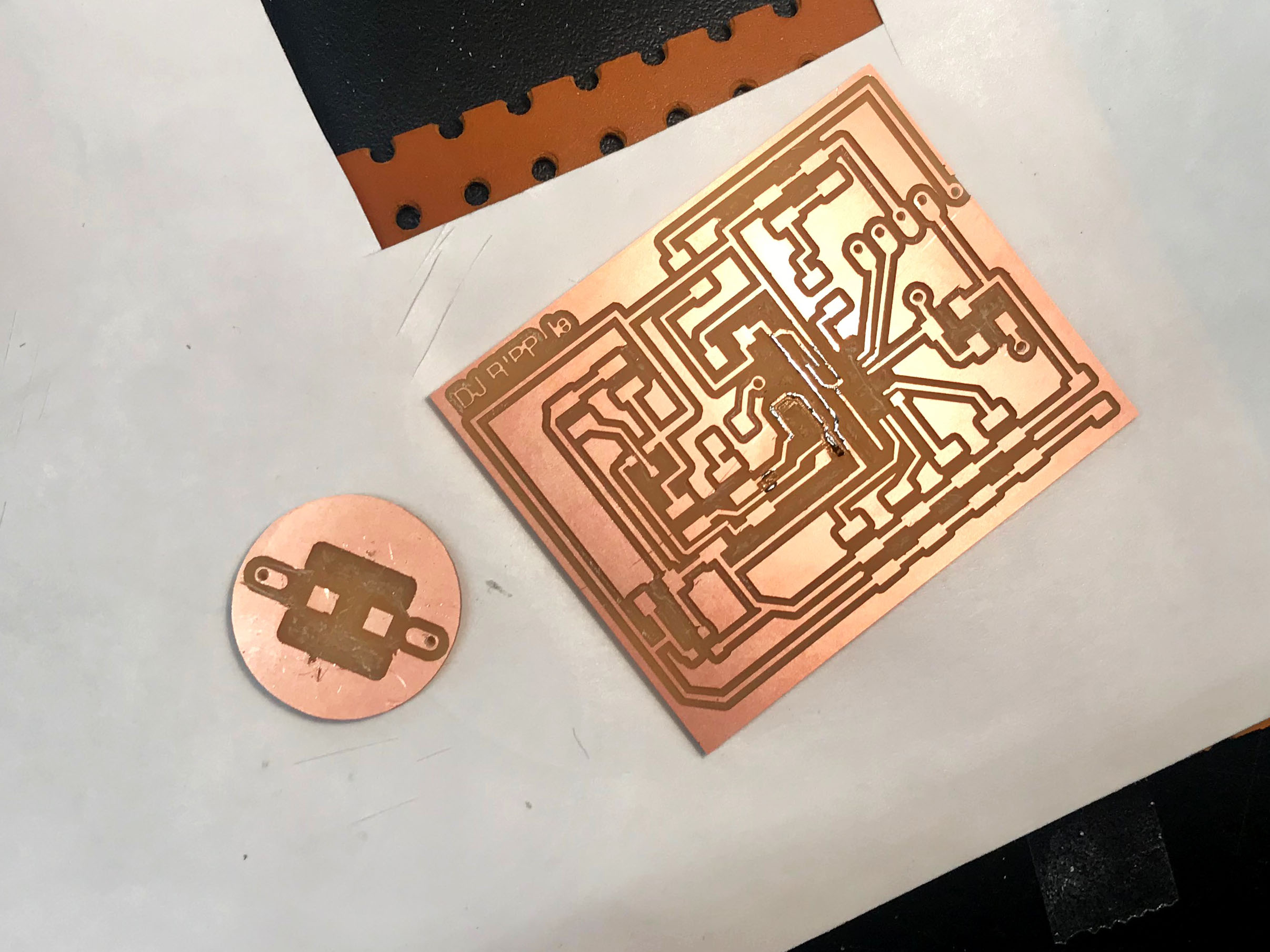
Figure 47. After clearing a few bits of copper I had my boards.
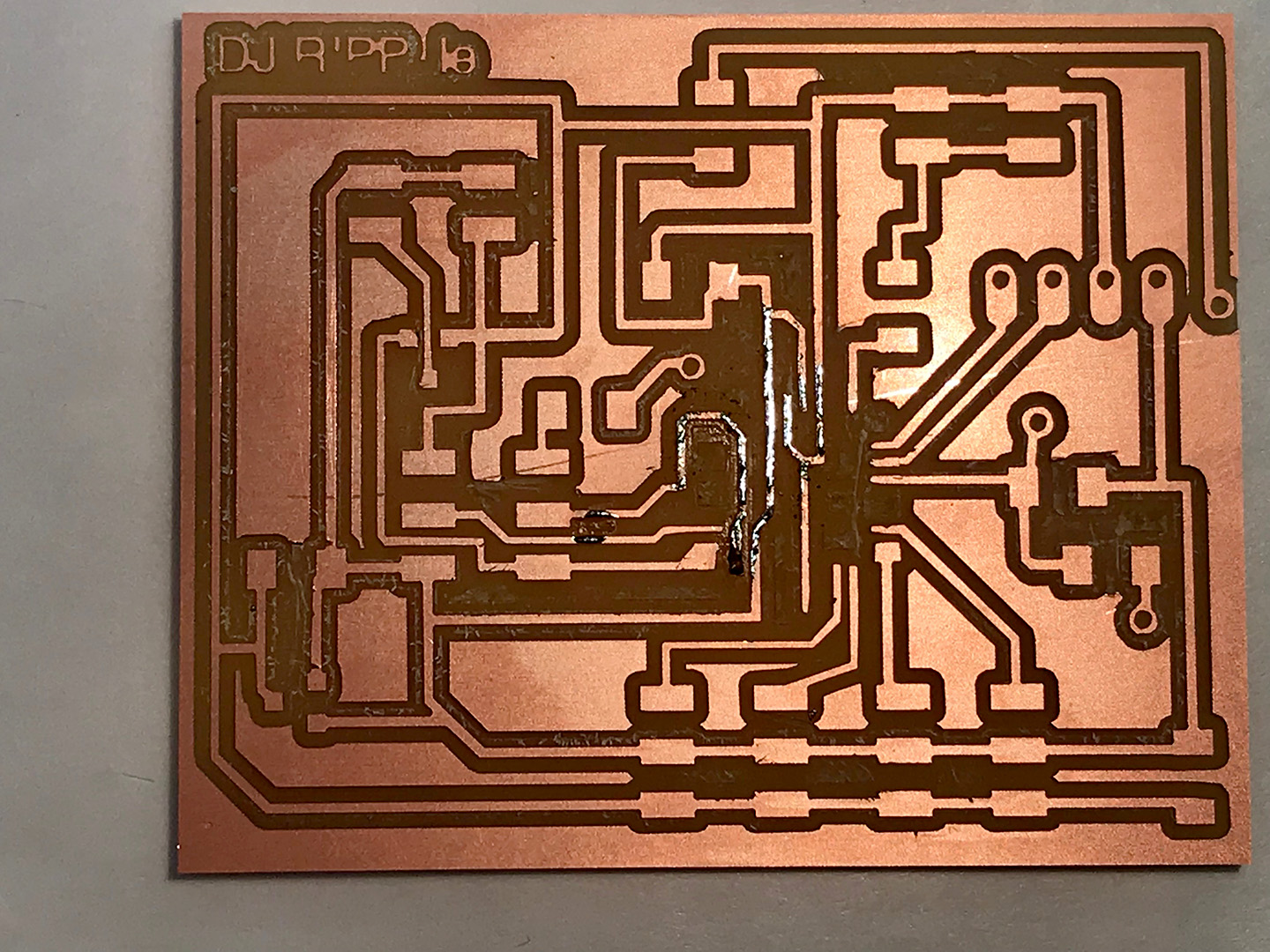
Figure 48. Dixon advised me previously to add a layer of solder to any segments I felt were too thin, for reinforcement. So I did this for the pieces under the ATMEGA.
9. Solder and Program
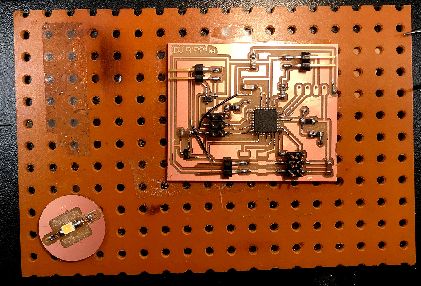
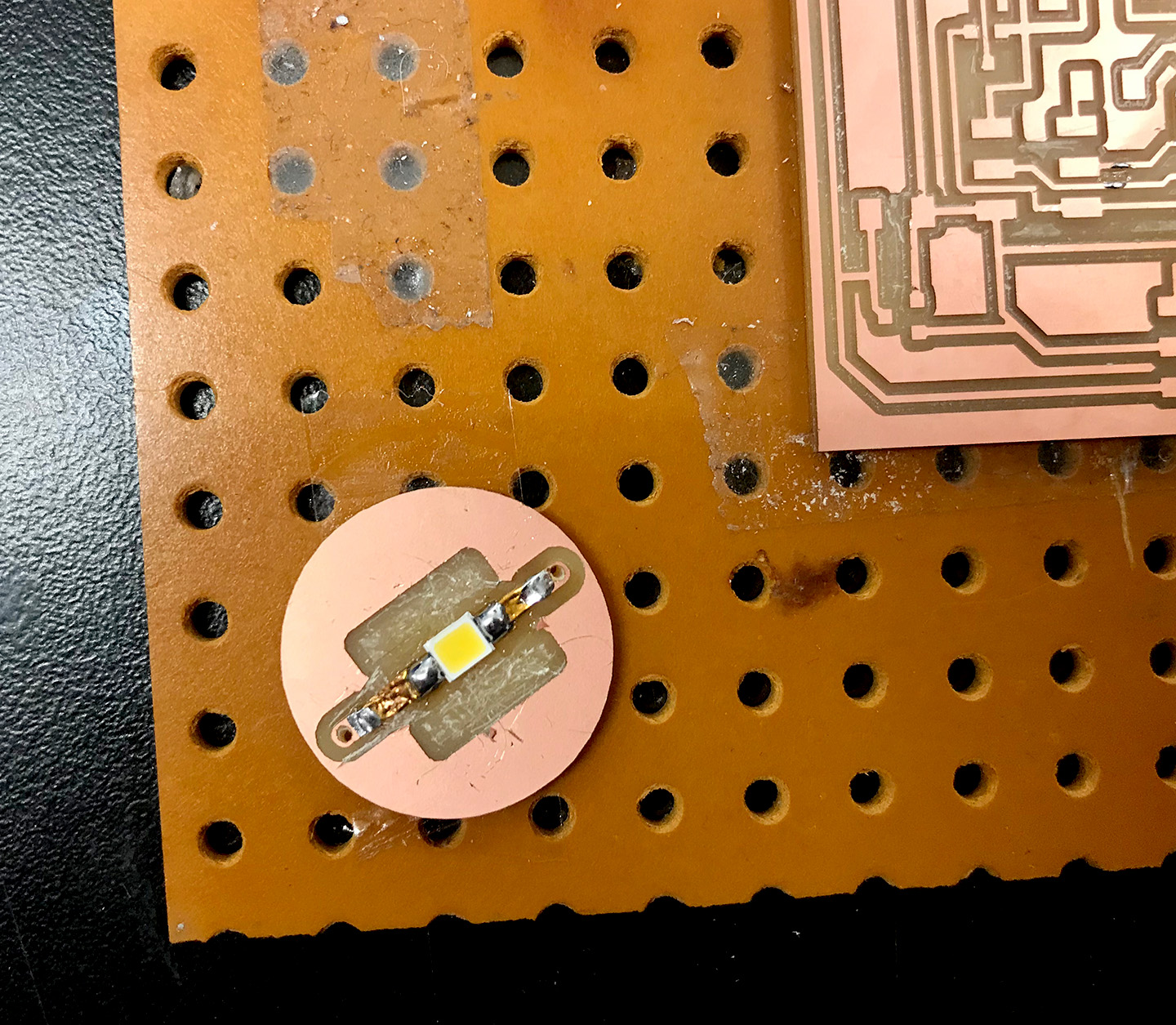
Figure 50. I added in strips of copper vinyl to connect the pads to the vias and soldered on my little superbright LED.
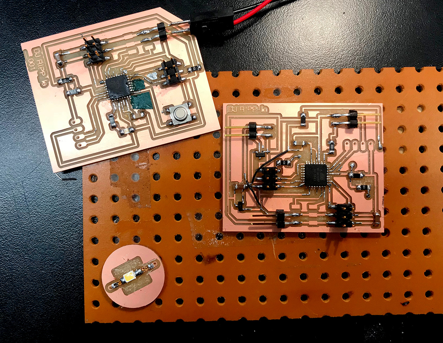
Figure 51. All three of my boards. I wound up having to jump a few wires as I wasn't sure I had done the speaker components fully correctly.
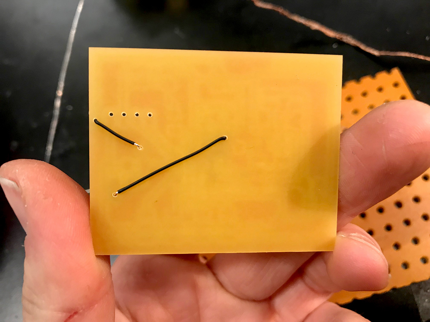
Figure 52. The Dremel holes were perfect and the vias turned out quite nicely.
10. Lasercut Middle Disk for Light + Discover Stand
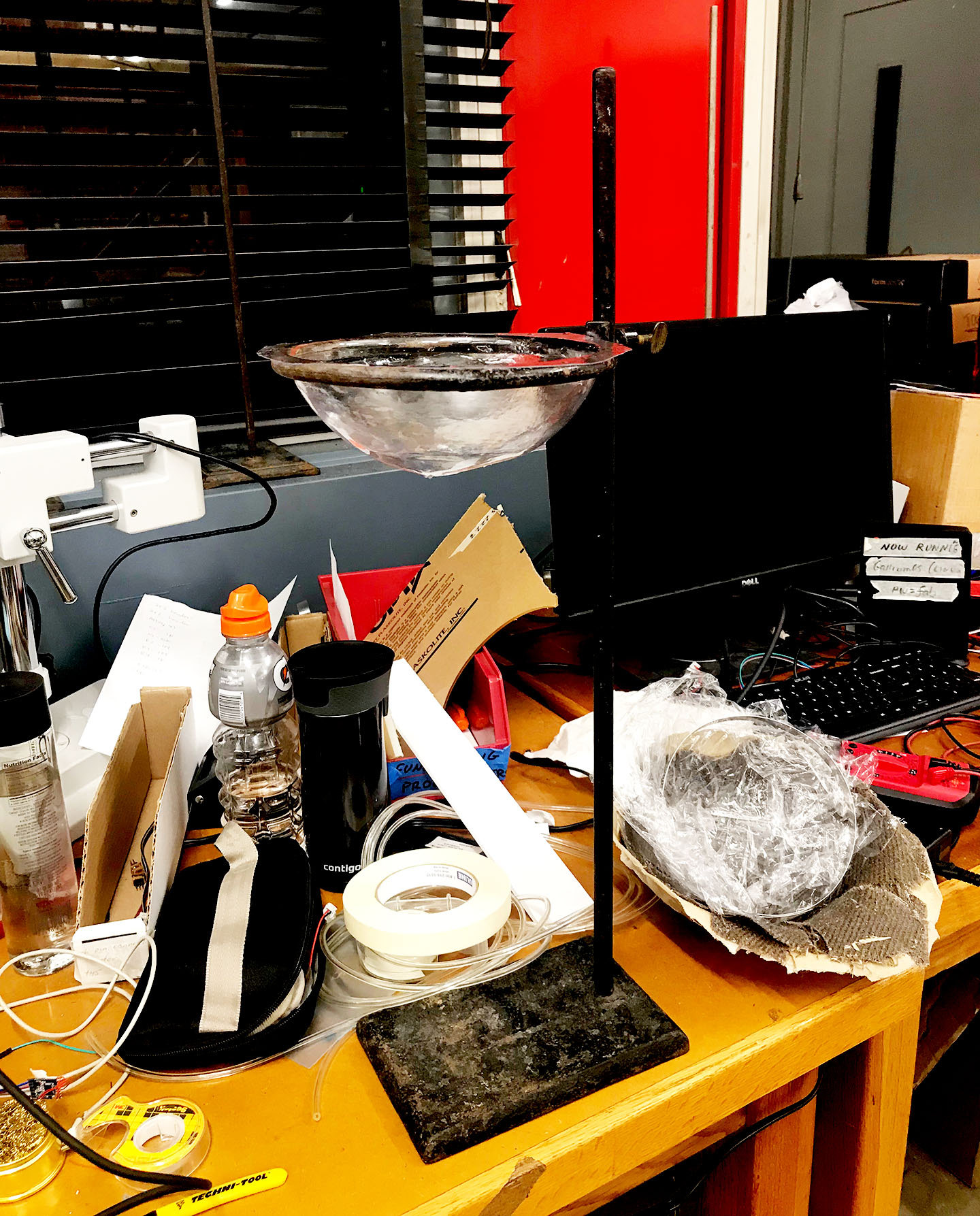
Figure 53. Looking around the lab for scrap material for my turntable I found this perfect stand which fit like a glove on my orb piece! I decided to adopt it.
Figure 54. I also found some scrap acrylic which I used to make an interstitial layer in between the top and bottom orb to seal in the water and also to hold the LED. I lasercut a series of acrylic discs which I layered in the center to perfectly hold the LED in place, and a cap to temporarily lock it in while in use.
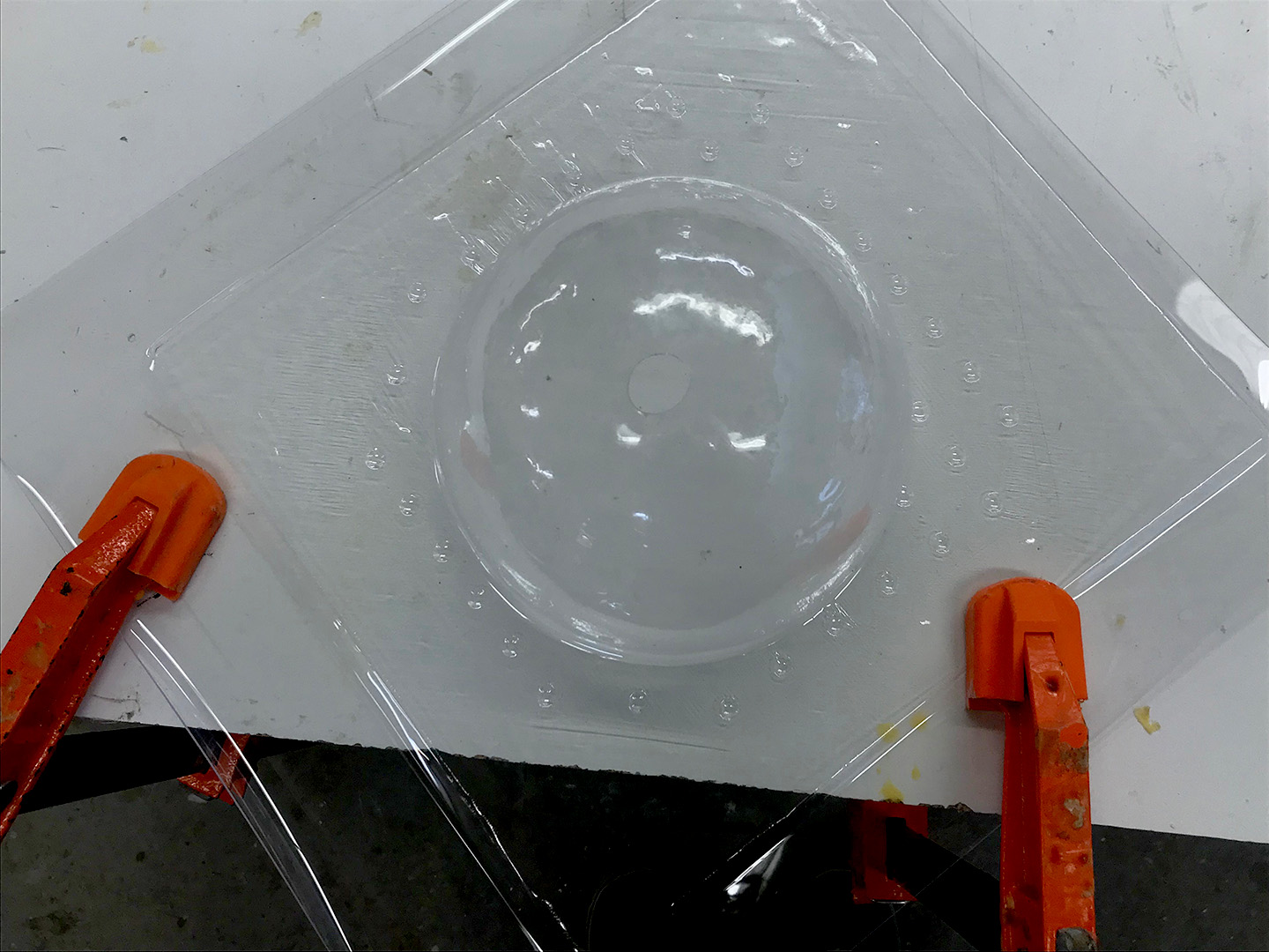
Figure 53. I tried Vacuum forming another orb with a hole in it, hoping it would come out more neat than the previous one.
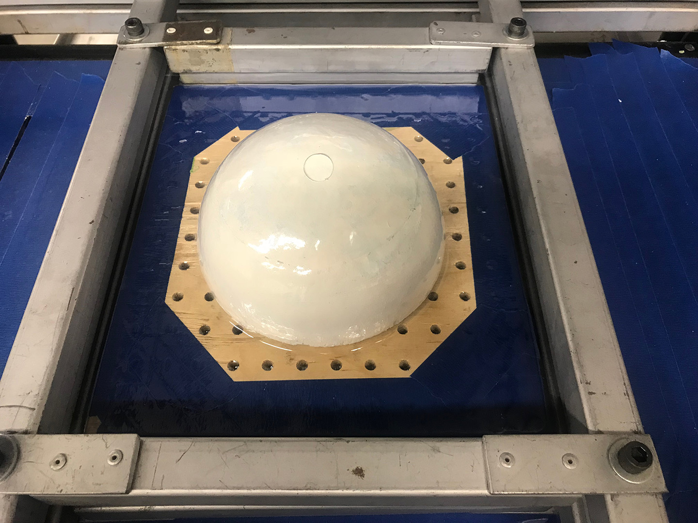
Figure 53.5. This one did stick a little so there is probably a limit to the Spackle Foam mold, I must re-apply Spackle for every third mold.
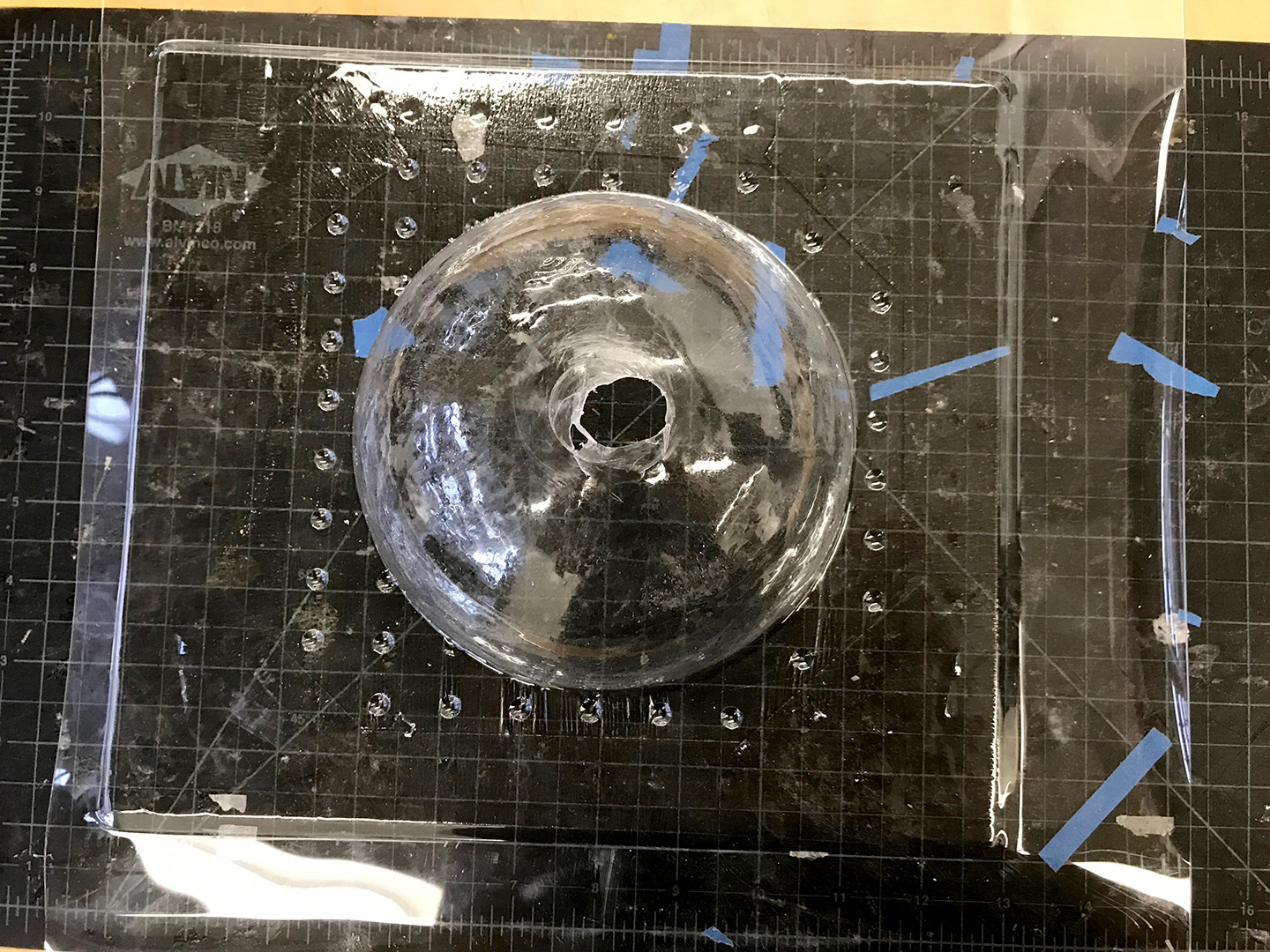
Figure 54. The drilled hole did not stretch as much as I'd hoped so I had to go back and manually cut out the hole.
11. Connect Boards
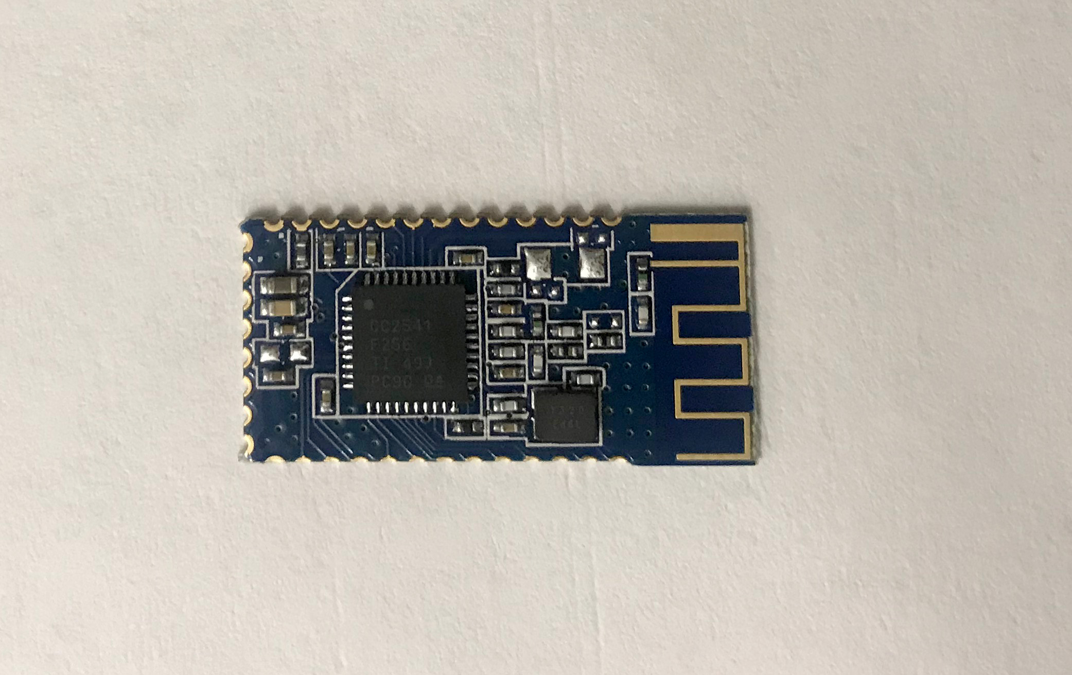
Figure 55. Here are the bluetooth modules I experimented with in Networking Week - the BLE HM-10. I chose them for the extensive documentation. In particular Dan Chen's Tutorial.
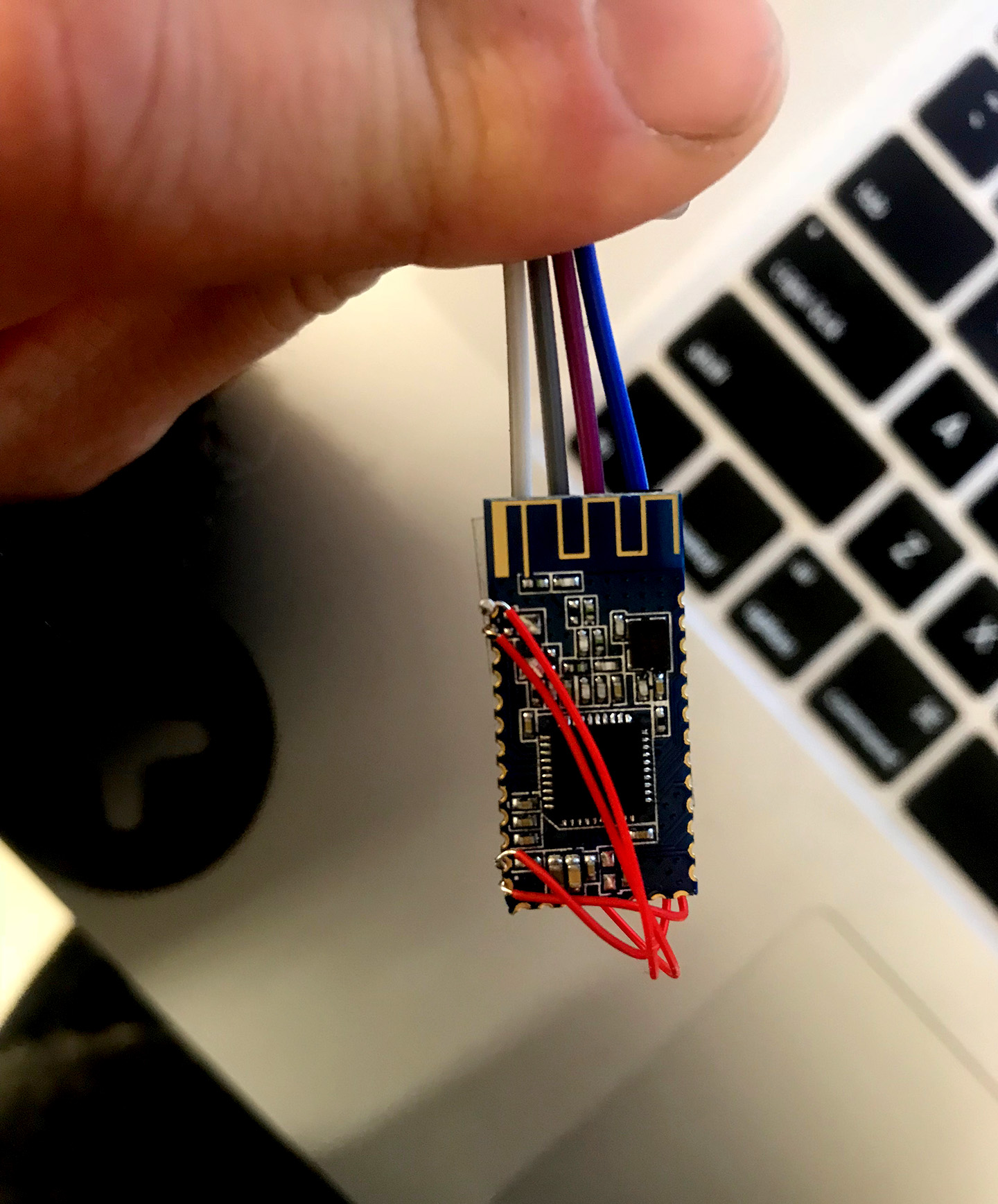
Figure 56. I pulled out connections for TX, RX, GND and VCC.
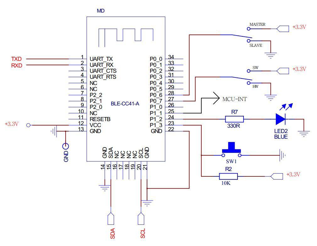
Figure 57. By following this diagram.
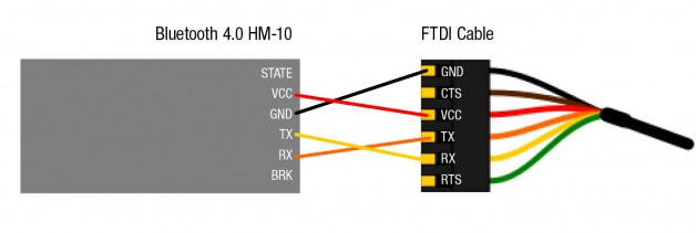
Figure 58. I then connected each to the computer via FTDI, and initiated and connected each to one another.
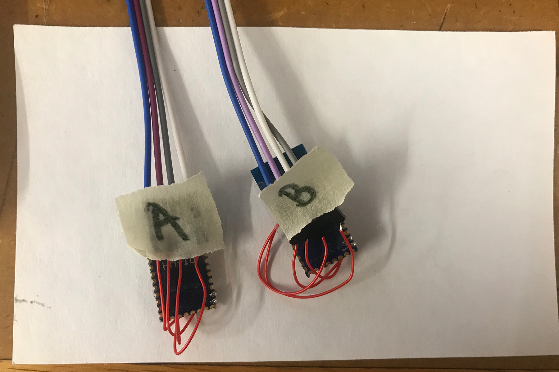
Figure 59. I established A to be Role[0] and B to be Role[1]
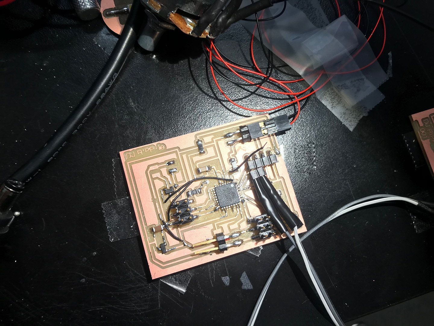
Figure 60. As I was still tweaking my code and wanted to make sure it worked before trying out the Bluetooth I just directly(via a serial bus) connected TX to RX and RX to TX using the Gray and White wires attached to the port I'd made for the Bluetooth modules.
12. Write Code
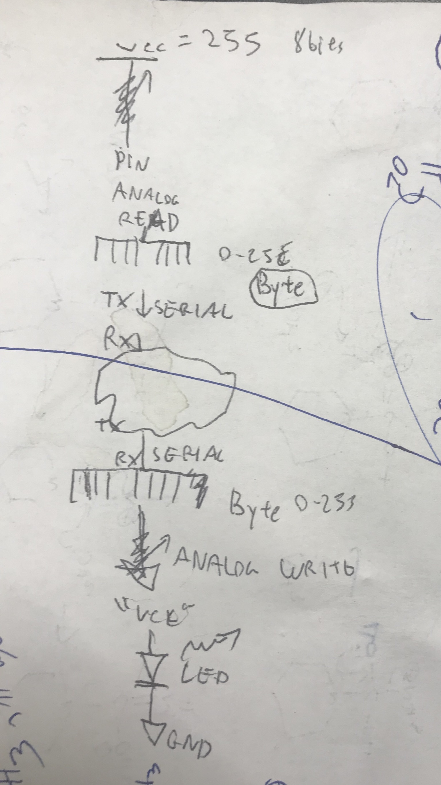
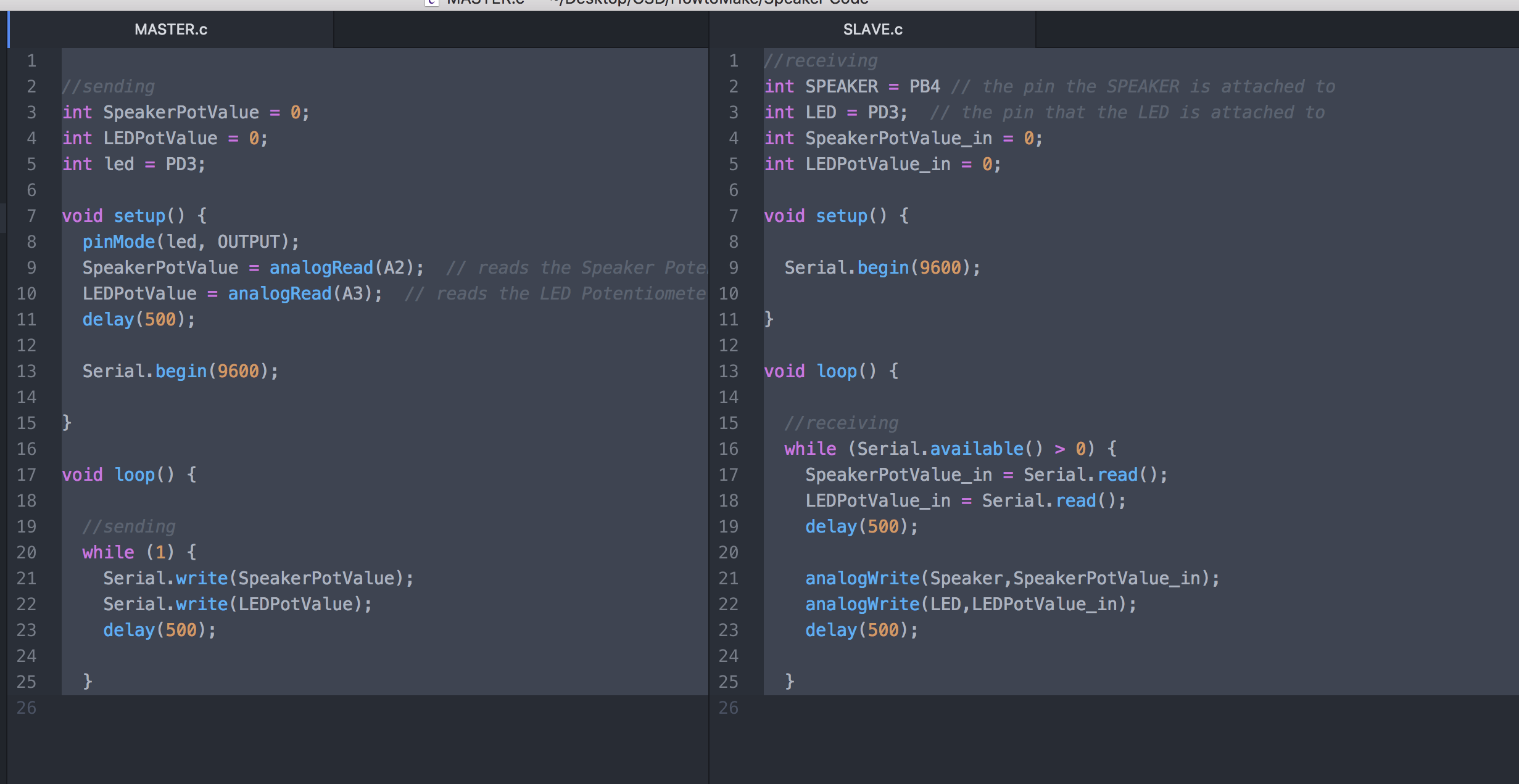
Figure 61. Yuval helped me map out what I want to achieve with the code and then checked in with me as I wrote it up to steer me in the right direction and get me up to date on the terminology.
Basically we discussed how Serial worked and what we we were reading vs what we were writing. It took me a few minutes to fully see the read vs write logic. I looked up on the Arduino webpage to see which variables needed to be called out and how to set up each statement.
13. Create LED holder + 3D Print Speaker holder
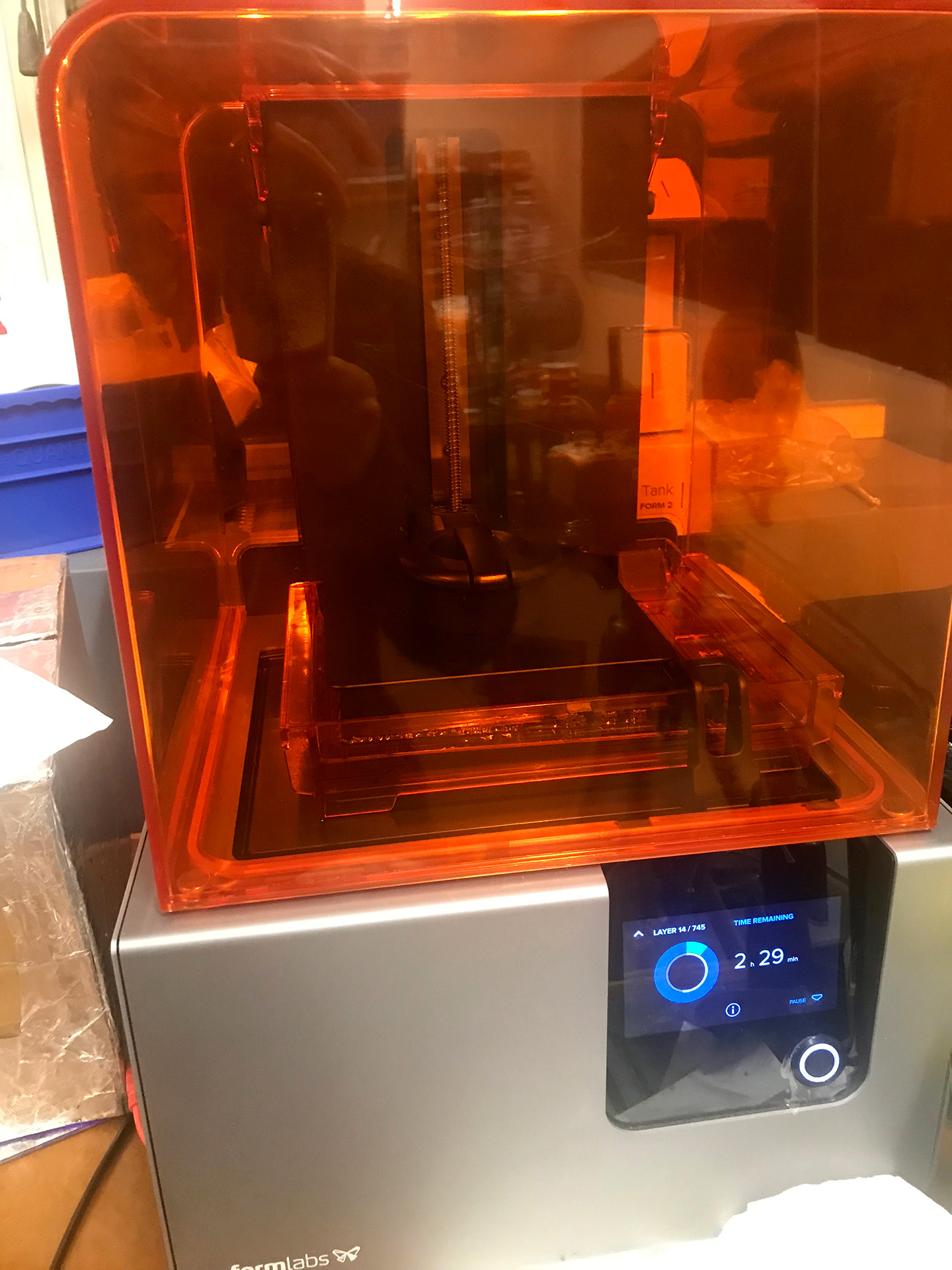
Figure 62. I had always wanted to try the FormLabs printer because of the high quality and incredible finish quality. Dixon gave me a quick overview of how to use the machine.
I measured my speaker and created this holder. I showed Yanru and Jessica and thankfully Yanru asked me how the wires would come out and in fact I had forgotten to design an outlet for the wires, so I quickly added this in before sending the file to the printer. I made each surface 3mm, based on the success of the 3mm discs I printed for the knobs. Dixon said in the future I can go as low as 2mm for surface thickness. I also had a terrible mishap when the entire power for that table went out mid-print because this was the table next to the computer many people were using to program their boards. Almost all of us have Macs and we never got the avrdude via the command line issue resolved so we've been using this computer. I resorted to using Arduino because it works directly from the Mac. In any case I had to restart my print which was frustrating, but I did get a chance to take the half print and test it with the speaker to confirm the fit. It was perfect, nice and snug! Since I've started measuring in Metric I've found everything to be far more accurate, and have even had people ask how I am so precise with measuring. Metric all the way!
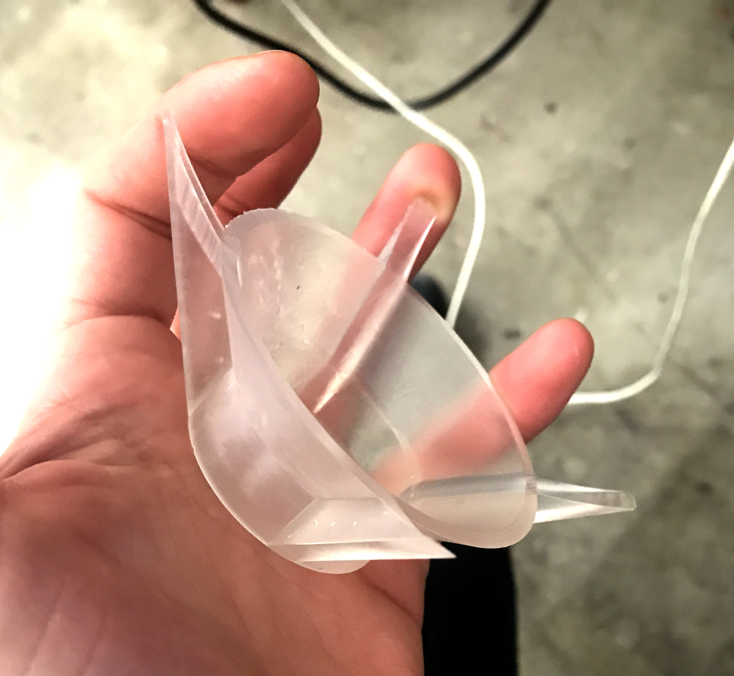
Figure 63. The print finally came out! Beautifully I might add.
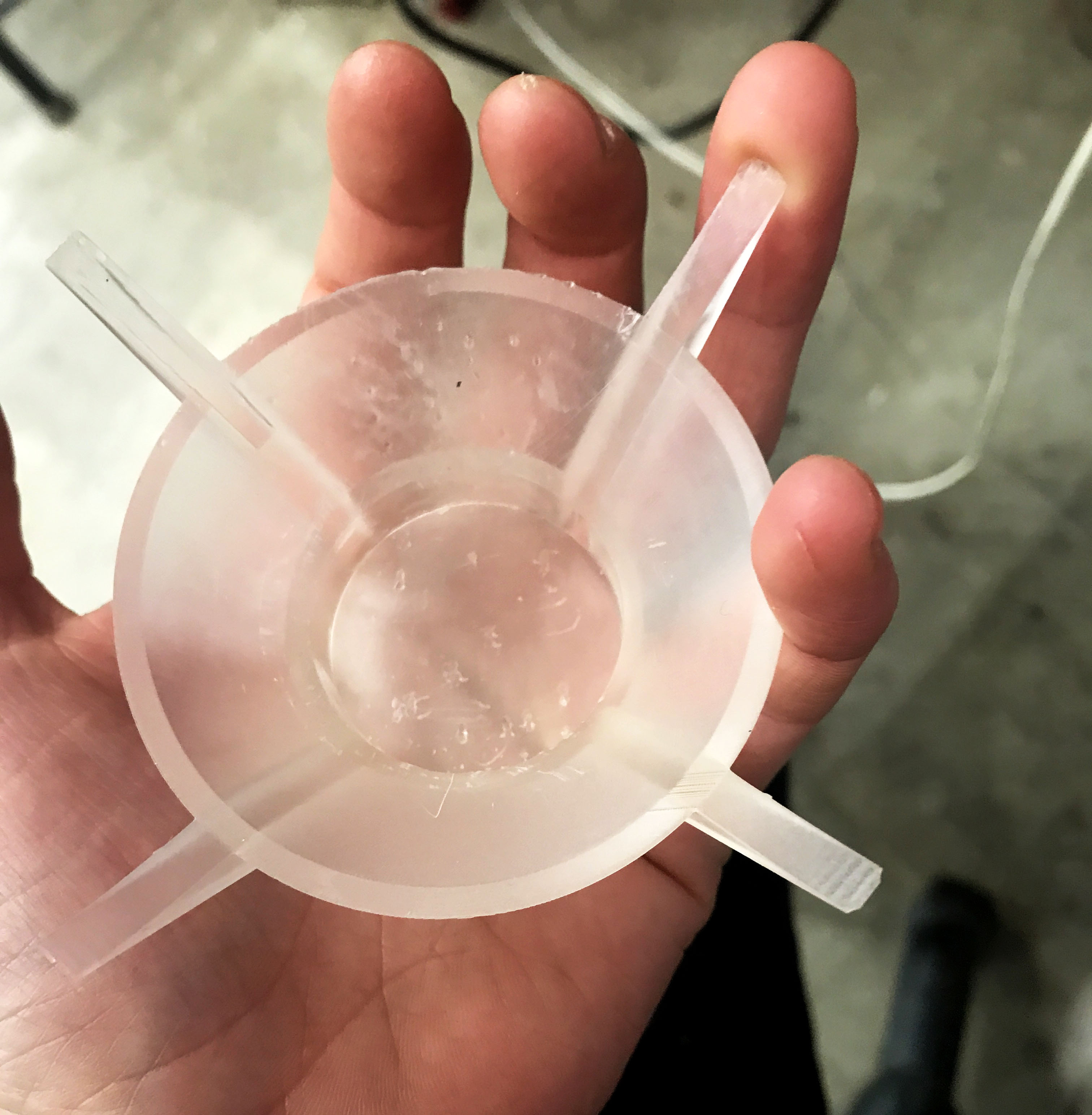
Figure 64. There were a few marks where supports had been which I later sanded with 1000 grit wet-to-dry sandpaper while wet, which cleared any imperfections and left a really nice smooth finish.
14. Test + Troubleshoot
Rob helped me to get the serial pins connected to an FTDI cable so we could plug it into my computer and read the serial messages using CoolTerm. We realized a few bugs, one was a hardware wiring issue which I fixed, and a second was that we had to divide the Serial.Write messages by 4 to remap the potentiometer values, 0-1024 to the LED and Speaker ranges which were 0-255 because they were being AnalogRead.
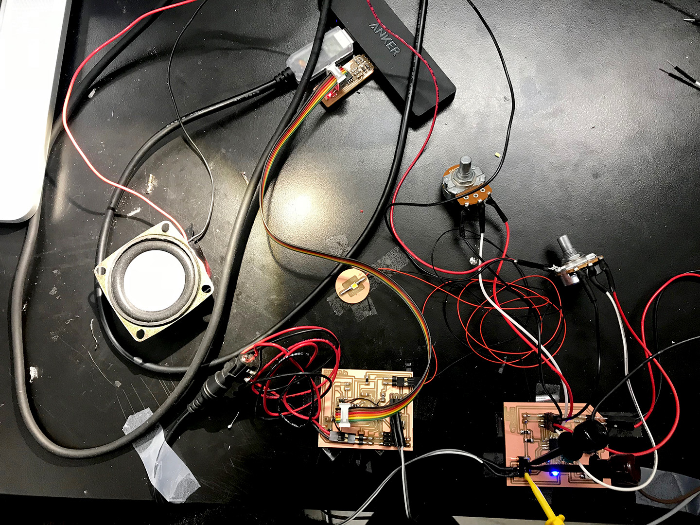
Figure 65. This was definitely the part I felt most helpless with, but thankfully Rob was able to guide me through! Once we could see what the Serial port was sending out we could test each potentiometer to see if they were working. I did have them plugged in incorrectly at first, and then we found one was not working so I had to inspect and rewire it.
I had just been taught how to make the Female crimp joints so one of them was not properly made, but after I started getting the hang of these I was very excited about them and had most of my components removeable so I could quickly update pieces and components or swap out the board, which I was really hoping to do, as it was getting to be quite a Frankenstein mess, but I ran out of time and it did work so I was told not to break what is not broken.
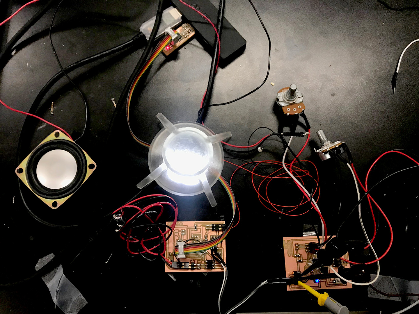
Figure 66. The little LED was so bright!!! I had originally wanted to do a full array but due to time constraints and how bright it was I stuck with just the one. I had to use my speaker holder as a shield while testing to avoid going completely blind though!
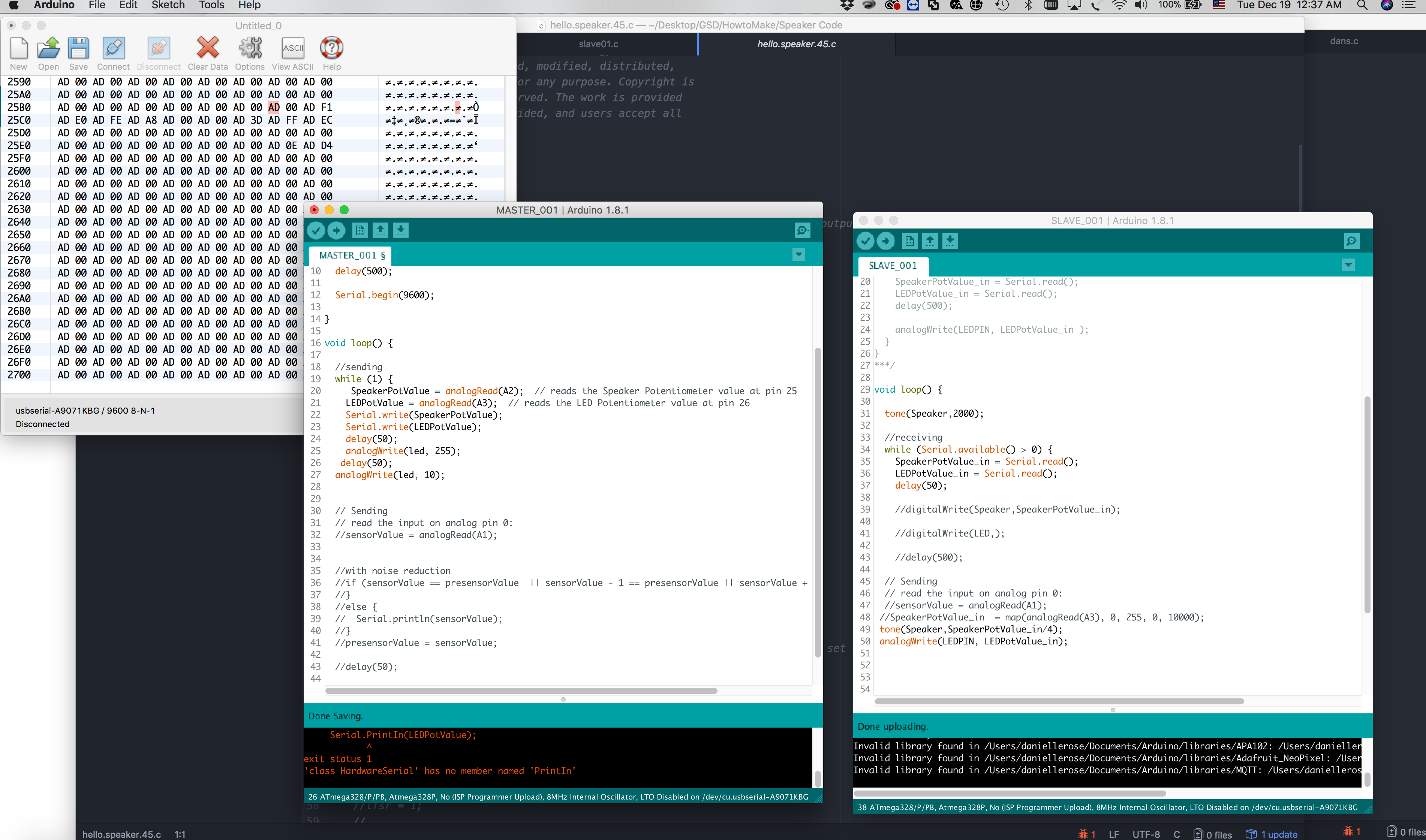
Figure 67. Rob helped me download coolterm which I was really excited about and we began attempting to decipher the serial messages and tweaking the code and hardware to make sure we were getting what we wanted.
Figure 68. Found this on a table on my way out and deeply sympathized with the solder.
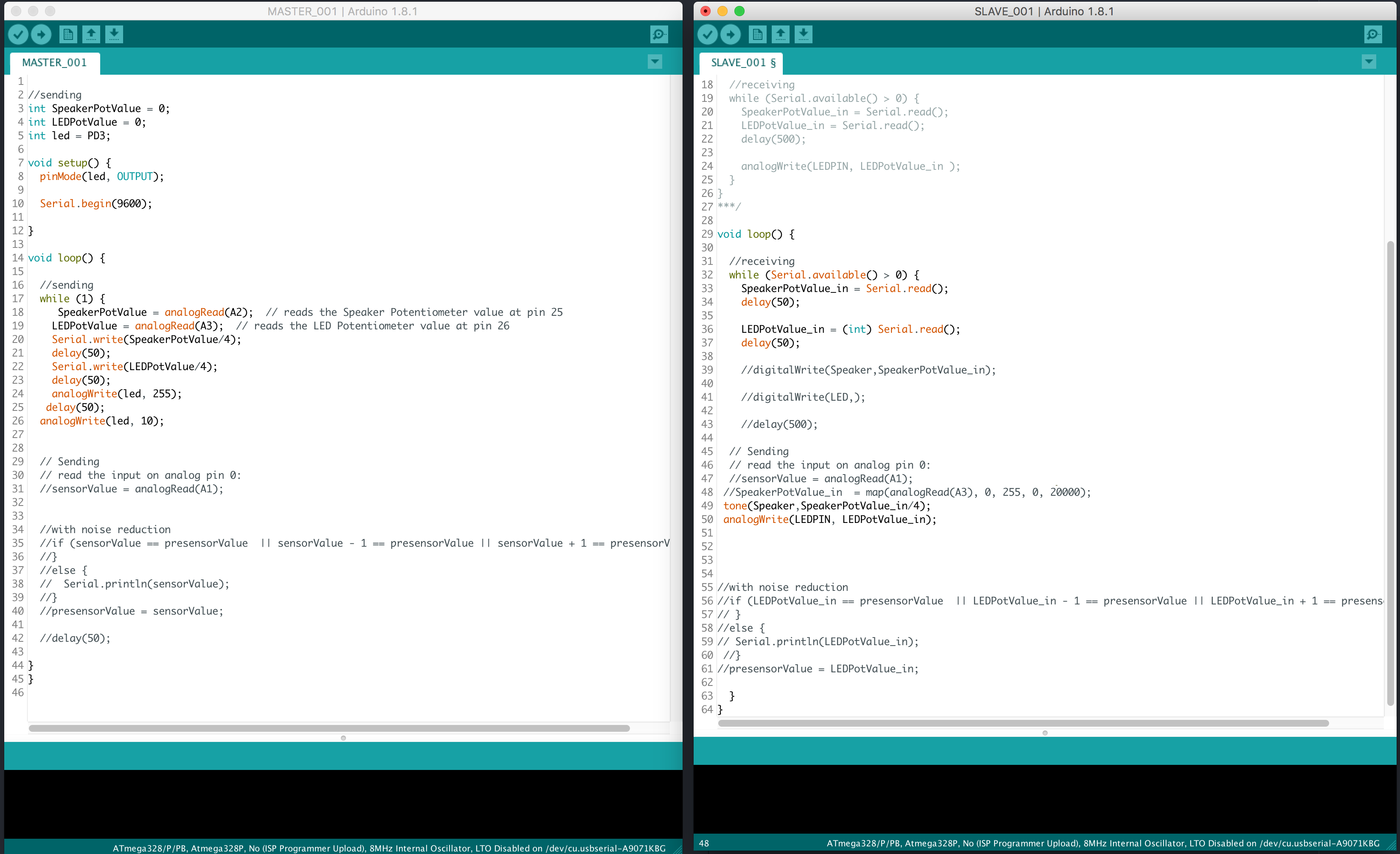
Figure 69. After many hours of troubleshooting I finally got a fully working code! and fully operating boards!
I decided to use the tone function in Arduino, which worked pretty well, there were a few beeps, so it wasn't a smooth transition between frequencies. I'd like to debug this at a future time. Also, a big isssue I had had which took me a long time to figure out, with Rob's help, that only some of the pins on the ATMEGA were accessible via Arduino language.I had to cross-reference the Arduino Pinout map with the ATMEGA 328p map until I found the few pins that did PWM and were called out on both, and were available on my board. In the future I'd like to learn C to avoid this issue. I did very thoroughly learn which pins do what. Rob helped guide me to discover that the OC pins were best to do PWM because they are connected to the clock/timer.
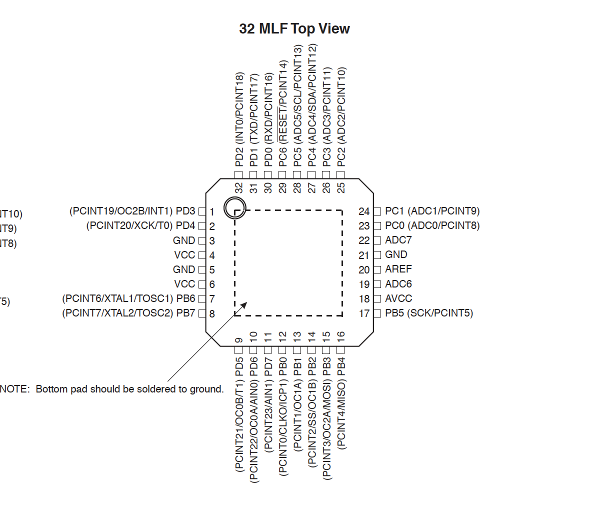
Figure 70. ATMEGA 328p Pinout
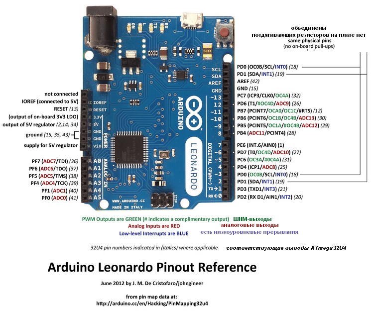
Figure 71. Arduino Mega Pinout
15. 3D Print Final Orb Components
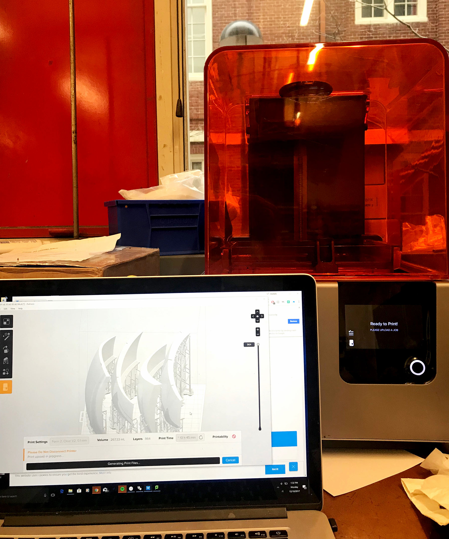
Figure 72. I designed a shell which I had really hoped to create and decided to go for it even though it was quite late in the game. I realized with the Layout button you could add more than one component onto the build plate and the software places them accordingly. I did realize the little Printability Section on the bottom right was telling me these pieces were too wide so supports were not able to fully surround the piece. I tried trimming them a bit but was still getting this error so I read further and it said to manually add supports to these edges. I figured out how to do this, and reduced from 4 pieces in one print to 3 and finally it was happy and allowed me to print!
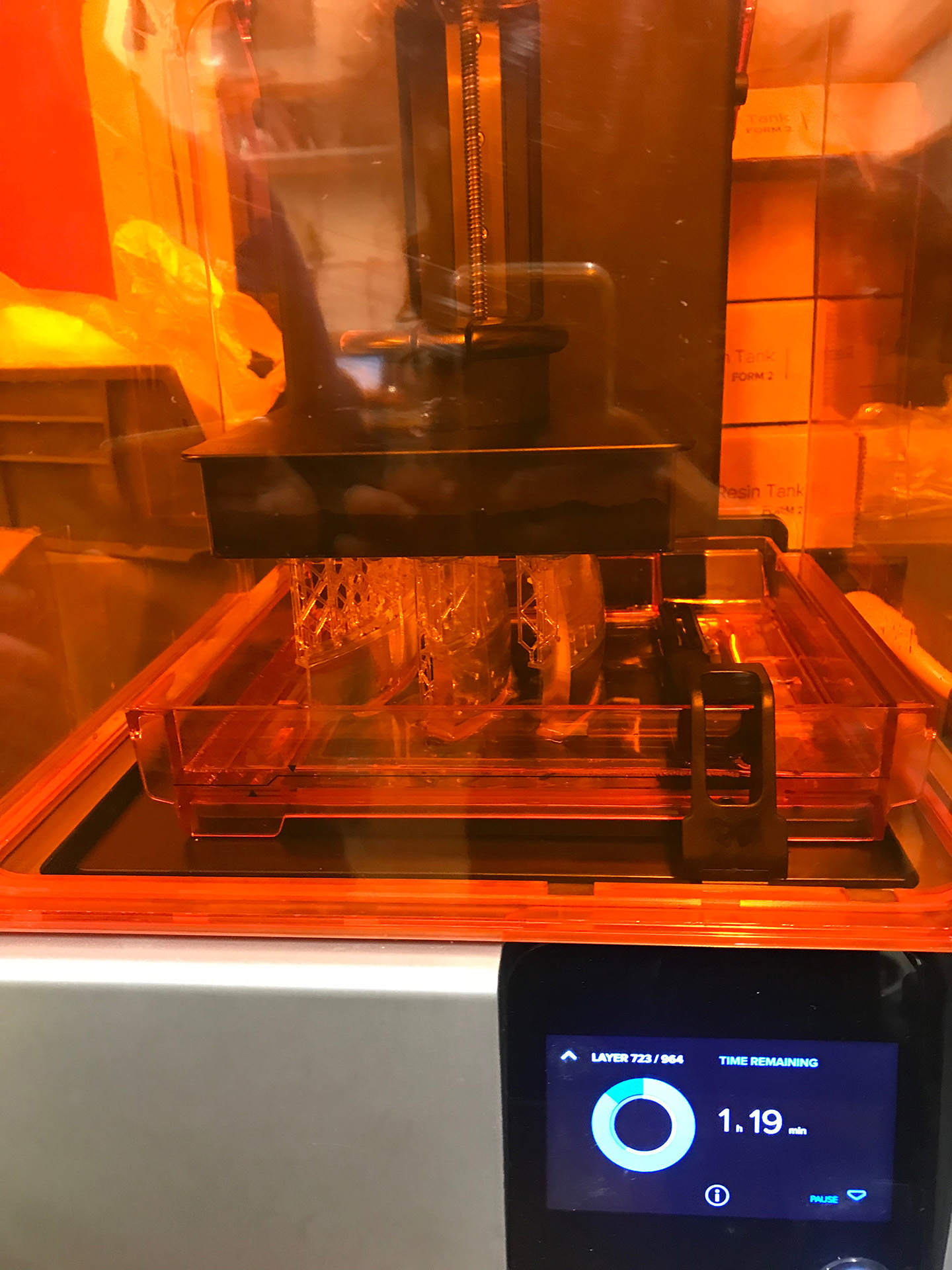
Figure 73. This machine is truly like magic!
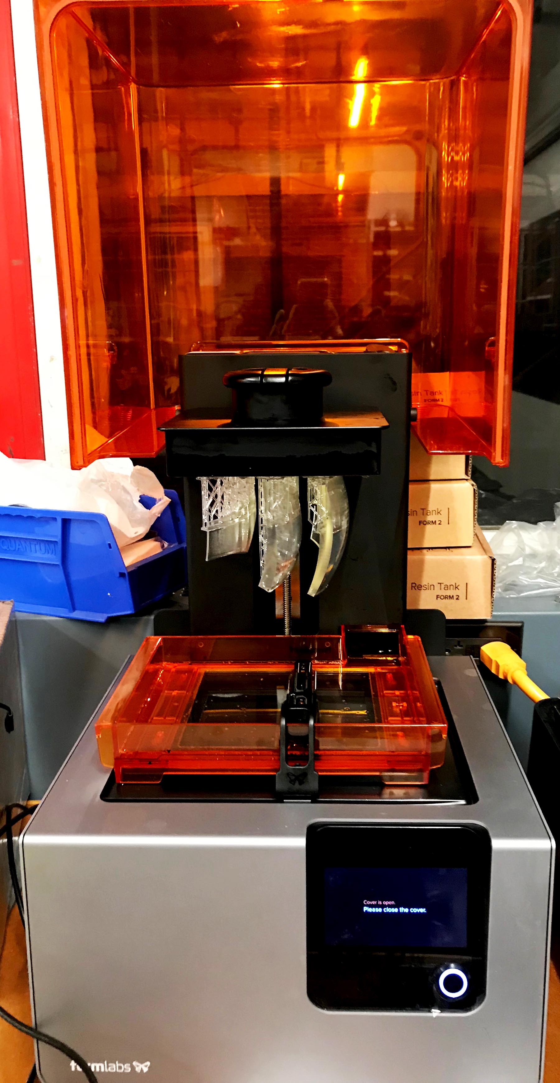
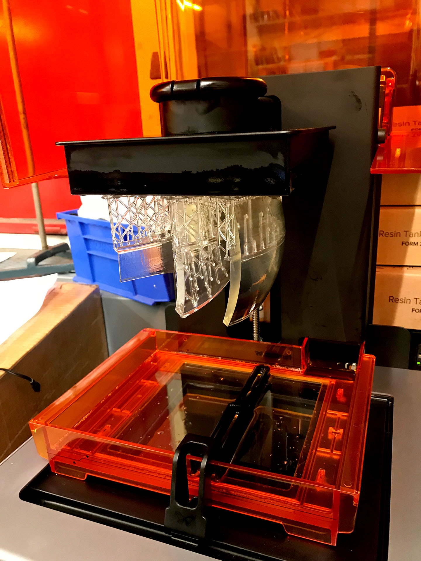
Figure 74. 10 hours later my prints were finished!
16. Fabricate Turntable
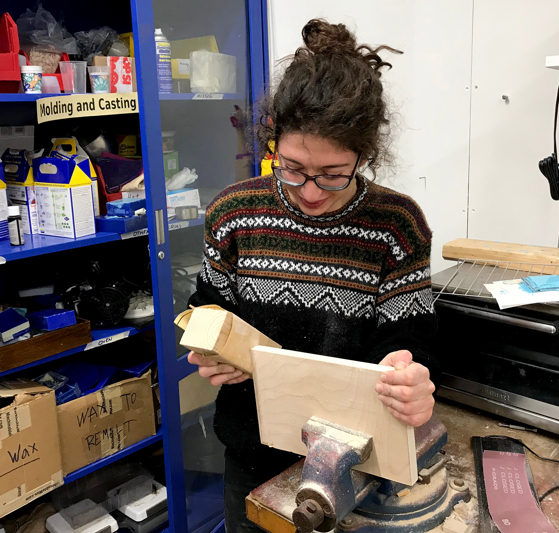
Figure 76. I found some scrap wood in the architecture shop and began piecing together the turntable, sanding the edges and drilling in holes for the potentiometers and wires to pass through.
17. Waterproof
The success of my tests with my cellophane layers had me fairly confident this would work, though I really should have addressed the waterproofing issue much earlier.
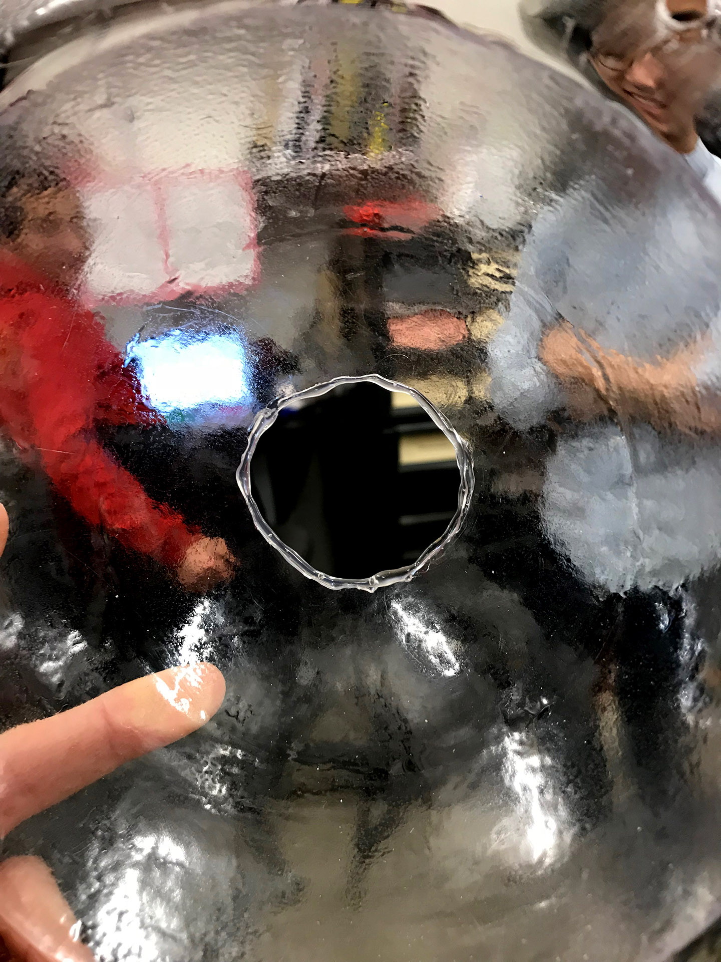
Figure 77. By following the rim with hot glue I could seal away the sharp edges and allow for thin plastic or latex to pass through and not get torn.
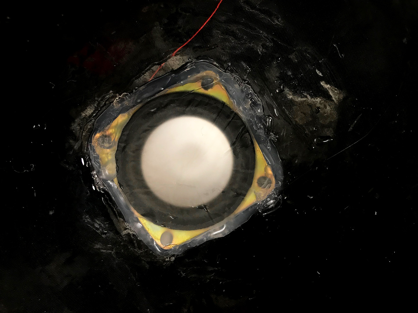
Figure 78. After struggling with the thin cellophane I decided to try a layer of latex glove I cut up and hot glued in place.
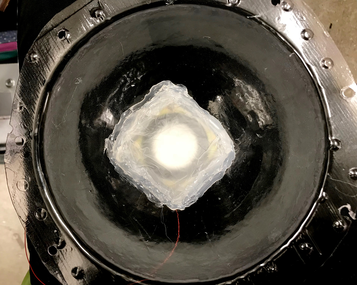
Figure 79. I added in a few more layers of latex and more glue until it seemed to hold water with no leaks.
Figure 80. I was hoping my speaker holder would cover up the ugliness of all the hot glue, which it just barely did cover up.
18. Assemble
19. FINAL presentation
I was so nervous and of course when I had to present the LED was blinking and the speaker while in retrospect may have worked was so subtle and I immediately thought it could be a waterproofing issue and said this. Afterwards the LED worked perfectly so I do not know what the blinking was about. Neil commented on the failure mode of wires everywhere which I also agree could have been the reason for both the LED and speaker malfunction. I taped them down to the rod later to make it look nicer for the open house and again regretted not putting everything together sooner than I had so I could have tested this more than I did as it was in its full form.
Figure 81. Overall I was happy that I got to most of the components I had hoped to fabricate and put together, and while it still needs a lot of work I think it looked good and I got a lot of intrigued visitors who also liked it.
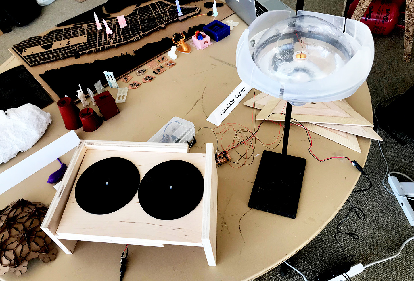
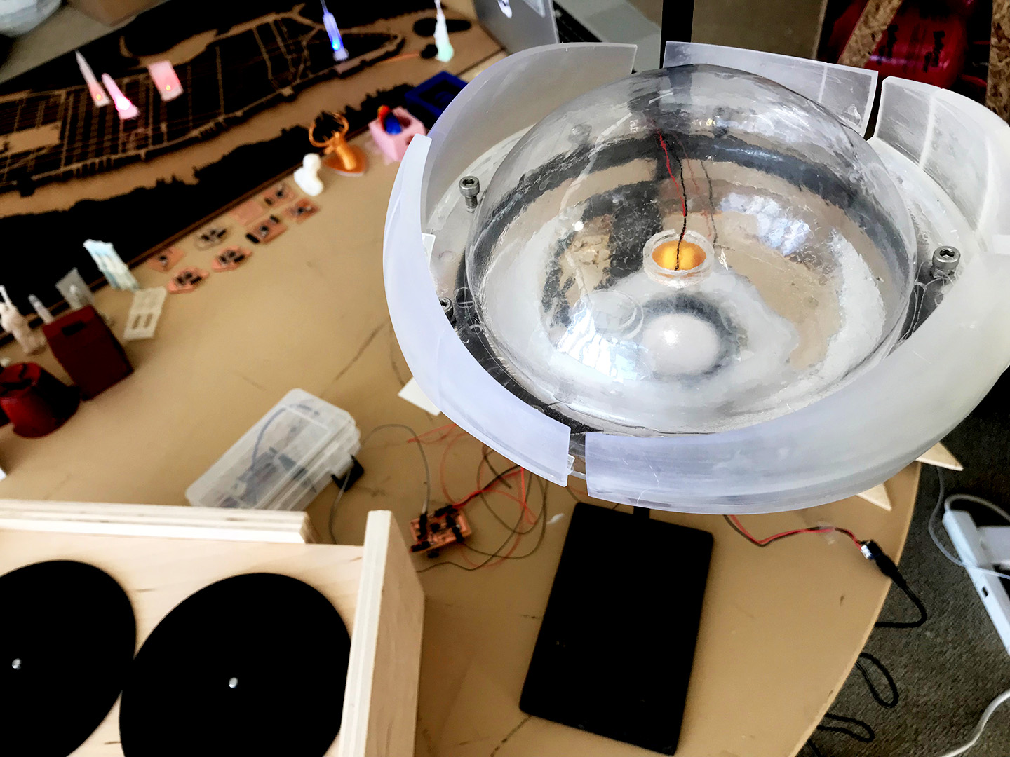
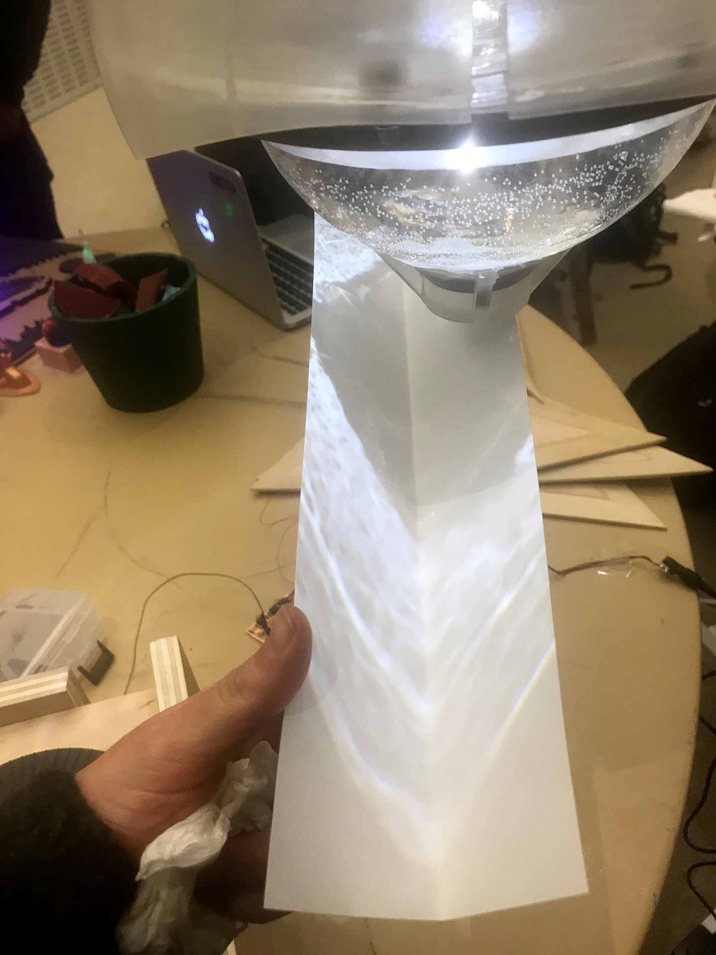
Figure 82. In discussing with visitors a friend and I agreed I should design a component that catches the reflections better becasue that was my key fascination and it was currently hard to make out the ripple patterns.
20. Adjustments
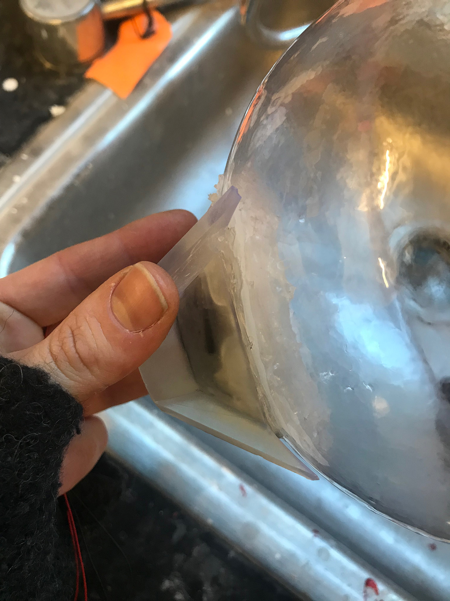
Figure 83. Luckily hot glue is fairly easy to take off.
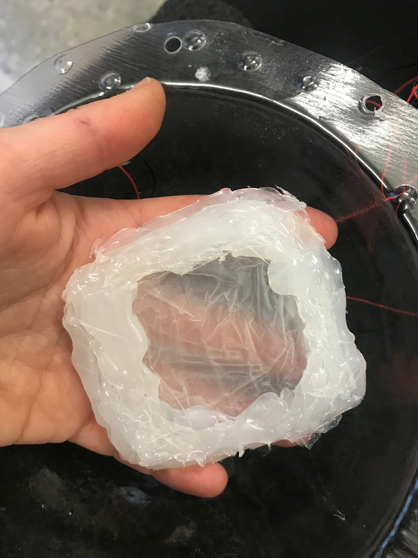
Figure 84. I was able to easily remove all the components.
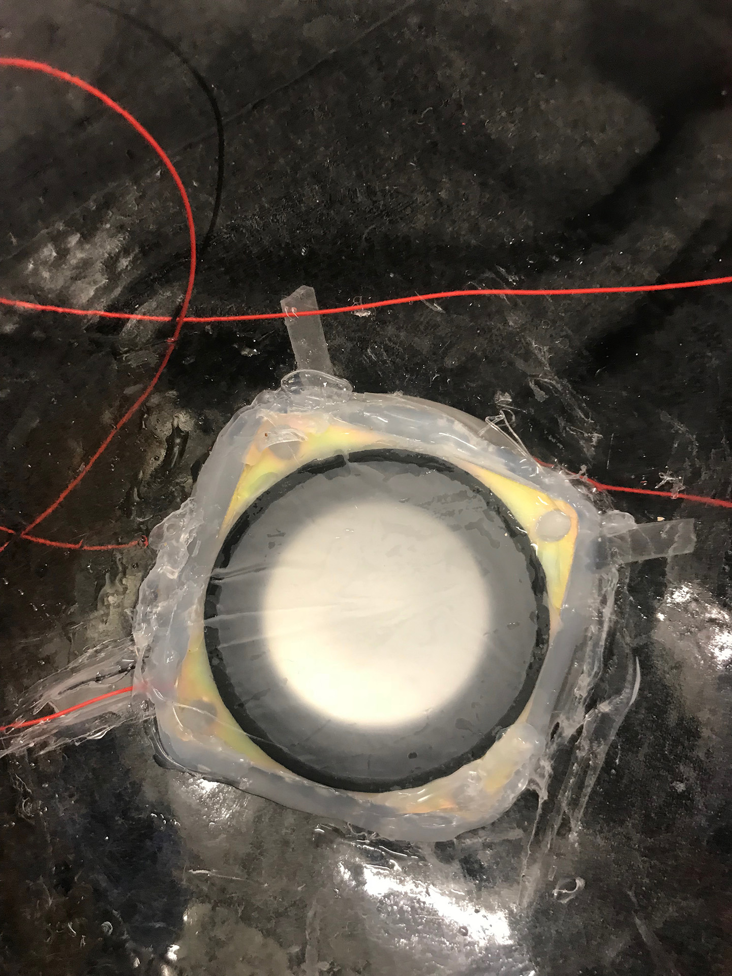
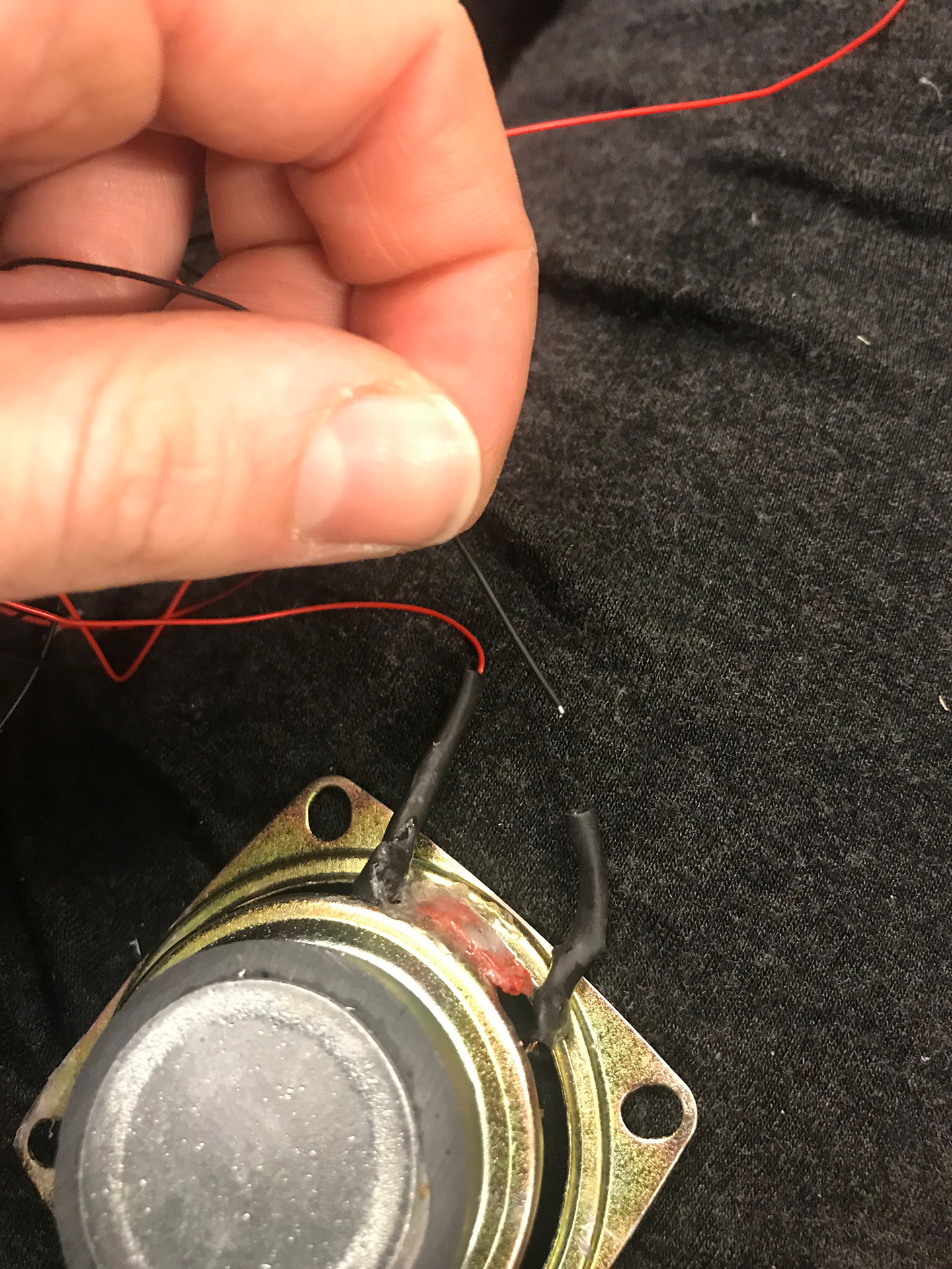
Figure 85. As it turns out a wire somehow got loose and the speaker in fact survived the water.
Figure 86. It lives!
Figure 87. Upon further testing I realized the 5V just didn't get the speaker to be powerful enough to really cause much of anything.
Figure 88. I hacked apart the speaker board, removing the ATTiny and combined it to my board by connecting ground and signal so I could send 9V to the speaker via this separate board. It worked better but was still very subtle so I think I might have to tweak my range of frequencies.
21. Further Experimentation
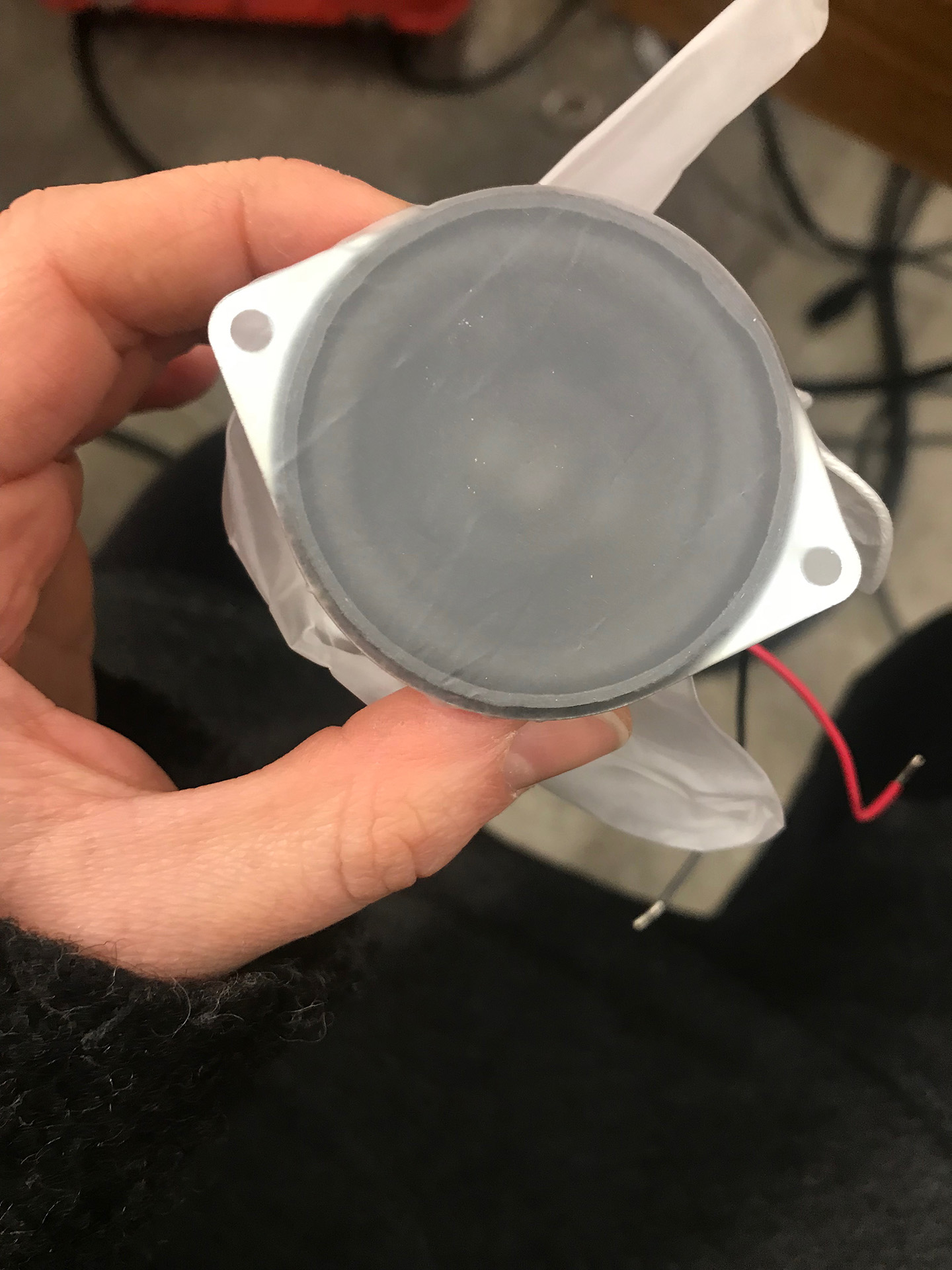
Figure 89. I wanted to try again so I found a new speaker in the shop and this time did not cut the latex glove but rather wrapped the glove around the speaker.
Figure 90. I secured it with rubber bands
Figure 91. And attempted to seal it in with clear silicone.
Here are some tests with a waterproof vibrating motor - which in the future, if I can calibrate it, I think will work better.