Danielle Aspitz
MAS.863 | How to Make (Almost) Anything
Electronics Design
_1. CAD Modeling
2. Fabricating
3. Programming
_
1. CAD Modeling
This week we learned to design, model and fabricate our own Printed Circuit Boards (PCBs)
This week was quite a challange for me. It took me hours to fully get comfortable with Eagle and install the Fab library, but once I was set up I found it to be pretty intuitive. Of course I stumbled upon just about every problem in the book but eventually I got a working board so that's exciting!
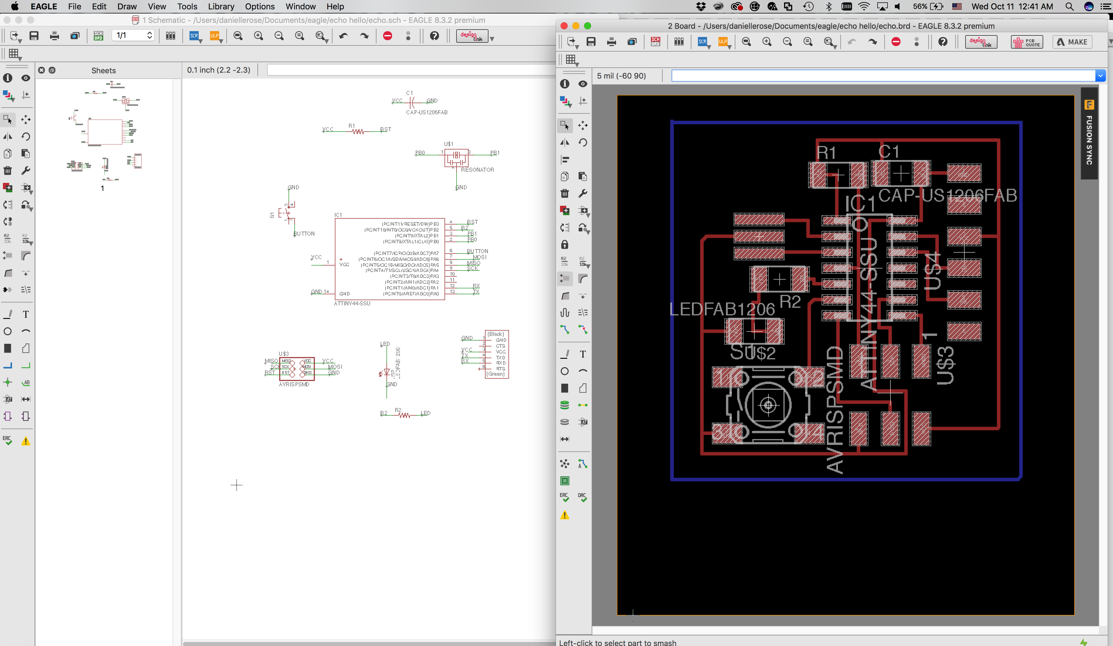
Figure 1. Modeling in Eagle
Brian showed me how to connect components via text, so I was playing around with this, though he later added it helps to keep small components together as they rely on each other and can be considered as one. This method is helpful when boards get really big and complex, however with this board it might be more visually effective to physically connect the wires.
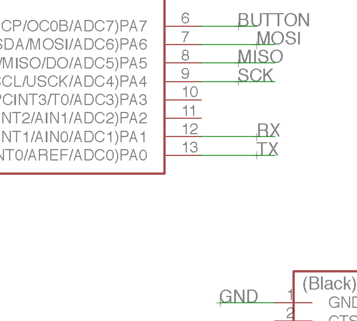
Figure 2. Connections in Eagle
I also learned the hard way that wires don't always connect to the node as you'd expect. You have to look carefully and make sure the wire is not overlapping the pin at all, but meeting it right at the tip. Some of my connections weren't showing up on my board and this was the case, they were not actually connected as they'd appeared to be. Here in the image they are all fully connected.
2. Fabrication
Once I had my traces set up I exported each traces and outline in monochrome at 300 dpi. There was some leftover space which turned out not to be a huge issue, but in the future I learned it is best practice to minimize the black background to get the border of the png as close to the board design as possible.
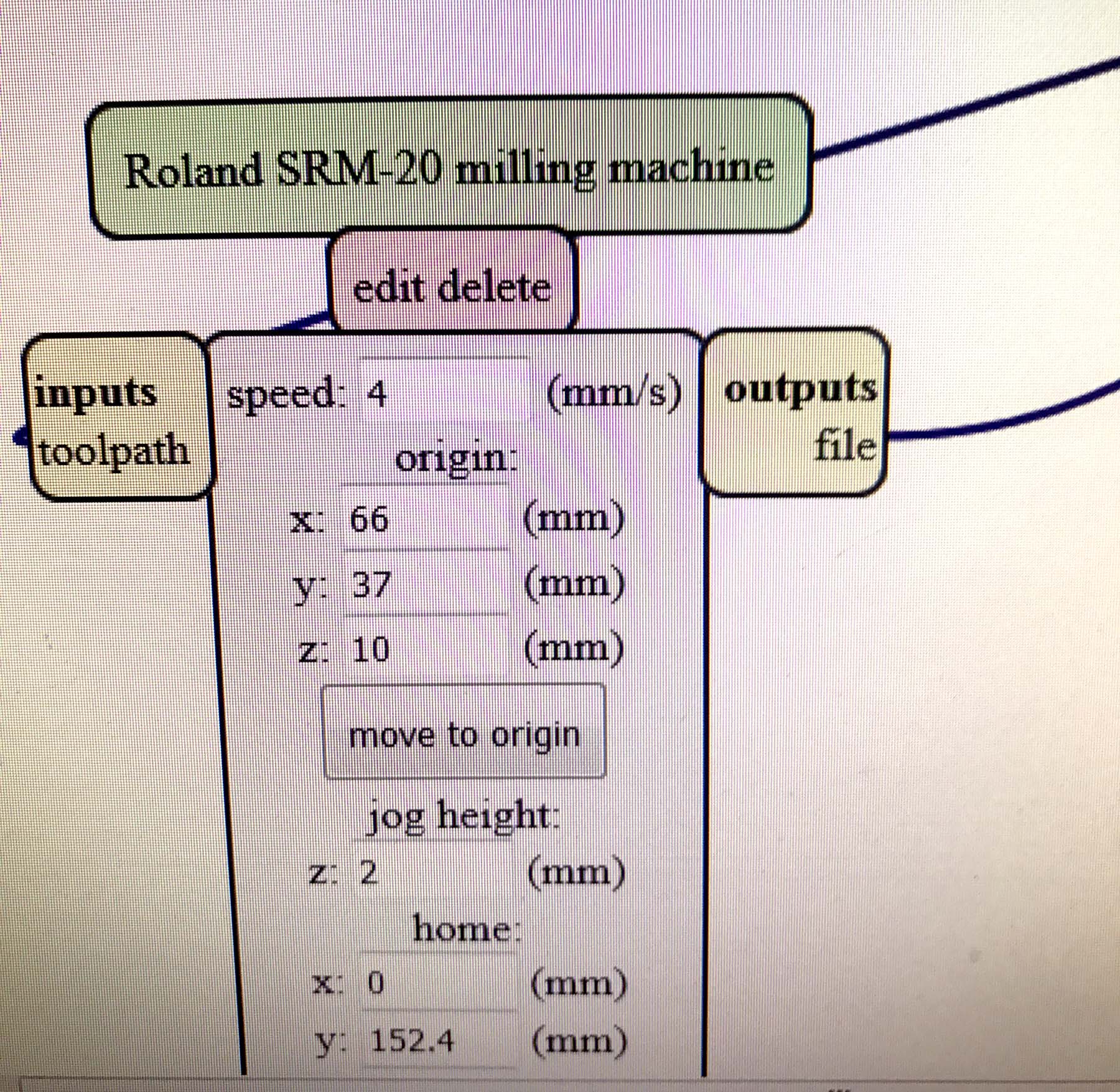
Figure 3. Checking Mods
For some reason zeroing the z height was not working. First of all I was trying the SRM 20 which was a huge mistake. I kept opening it too early meaning I had to start over a fair number of times. The Z each time was too high and so it was seemingly doing "air passes" at each of my attempts.

Figure 4. Infinite Surface creating an Endless Flow
This turned out to be very good because I could see the board was seemingly too big for the sheet. I tried to toy with the origin by actually subtracting a few mm each time hoping the design would fit if I eliminated the leftover space from the png. After a while of struggles Rob came in and noticed I had a Mac and asked if I knew about the Mac bug. Apparently Mac Eagle will export the png twice as big because it is confused by Apple's high definition Retina screen. For this reason in mods we have to put in "600 dpi" instead of "300 dpi" which was I what I exported as so the mods program will half scale the whole thing. Finally my board could fit! However the Z still wasn't cutting. I curiously decided to lower the origin height by 1 mm to see if it will get the piece to cut. This wound up going way to deep and after hours of frustration I finally switched to the older Roland Modela. On this machine everything seemed ok, but still my traces were only being delicately smudged on, and not fully cut throuhg. Luckily Rob came in because I was beyond frustration, and told me firstly, a suggestion first given by Dixon, to try to zero the bit at the middle of the board, because it turned out my corner was slightly raised. This still only resulted in a sheer grazing of the surface so Rob told me to double the cutting depth (from 0.1 to 0.2 - not a full 1 mm). Finally my traces were cut and soon after the board cut too.
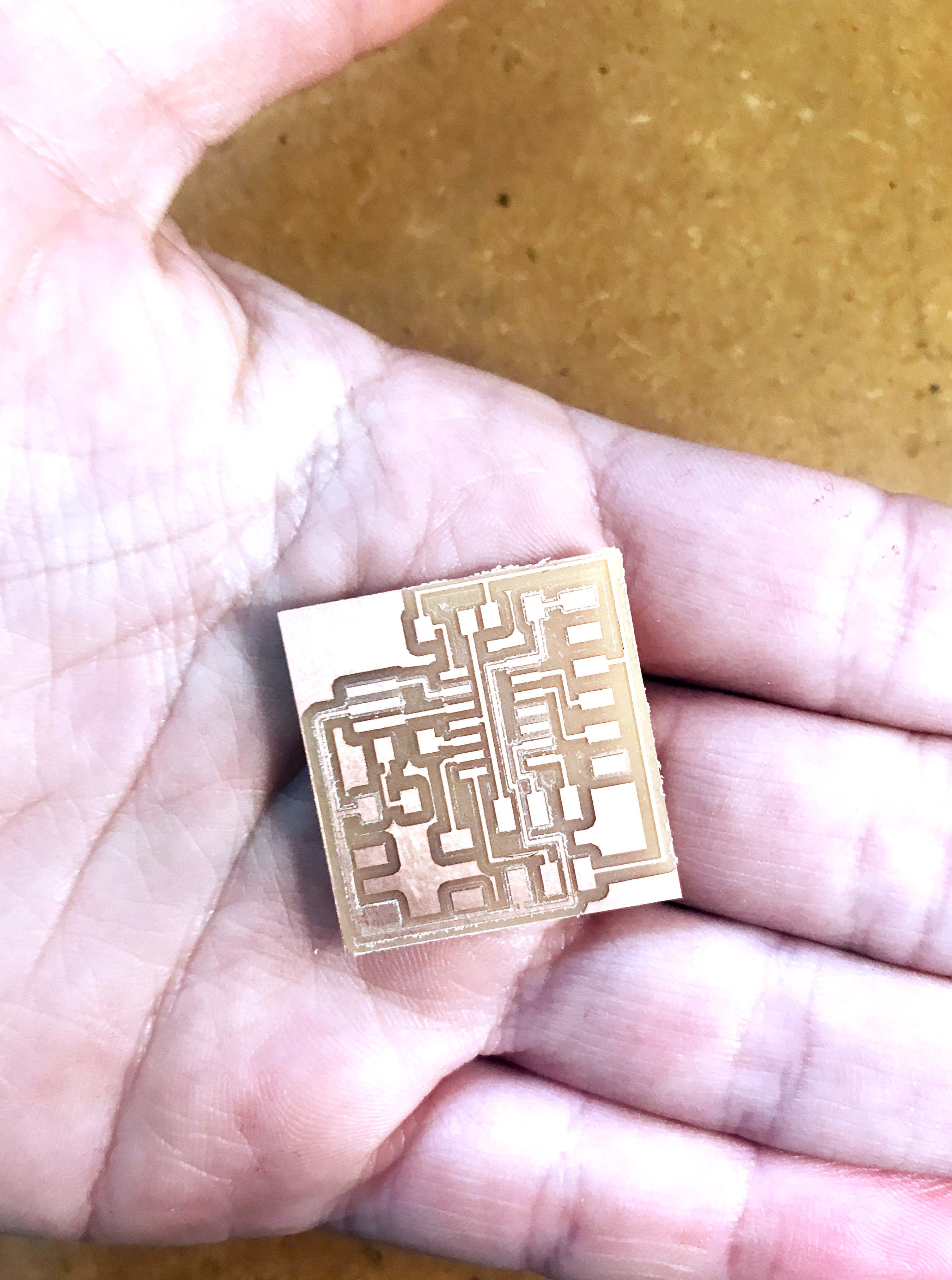
Figure 5. PCB board
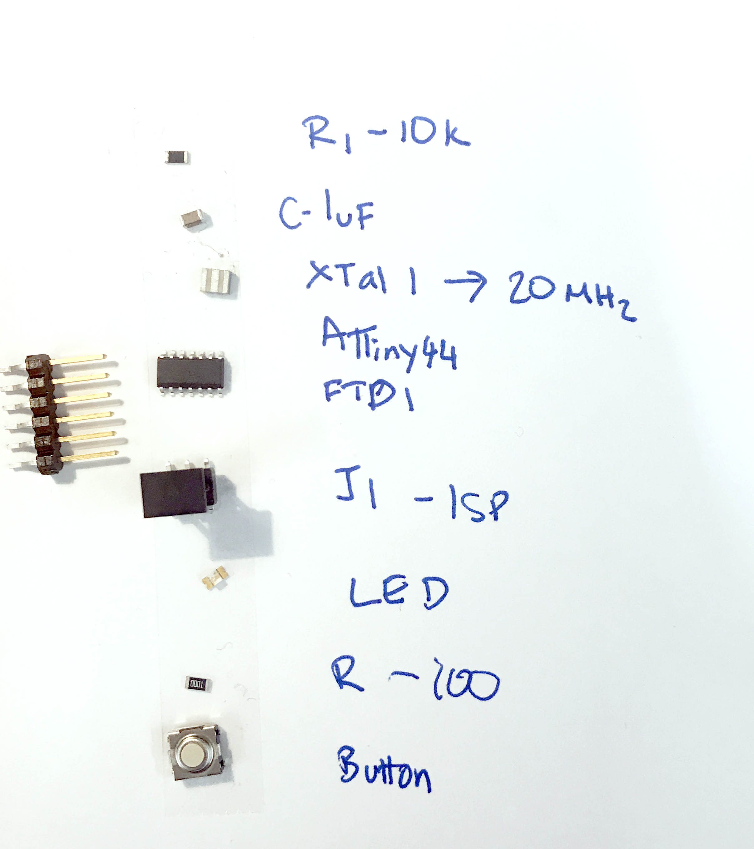
Figure 6. Parts Acquired
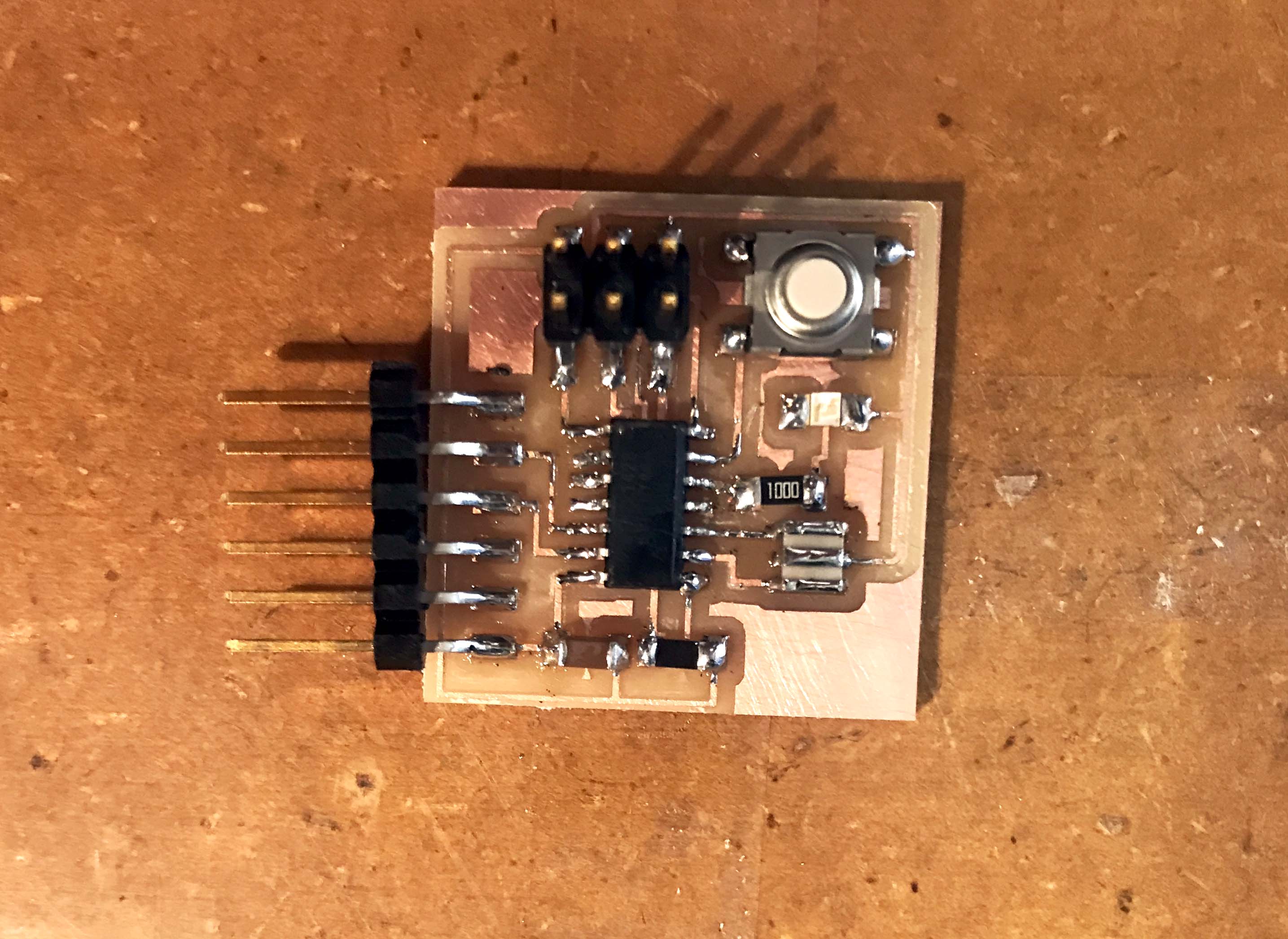
Figure 4. Soldering complete!
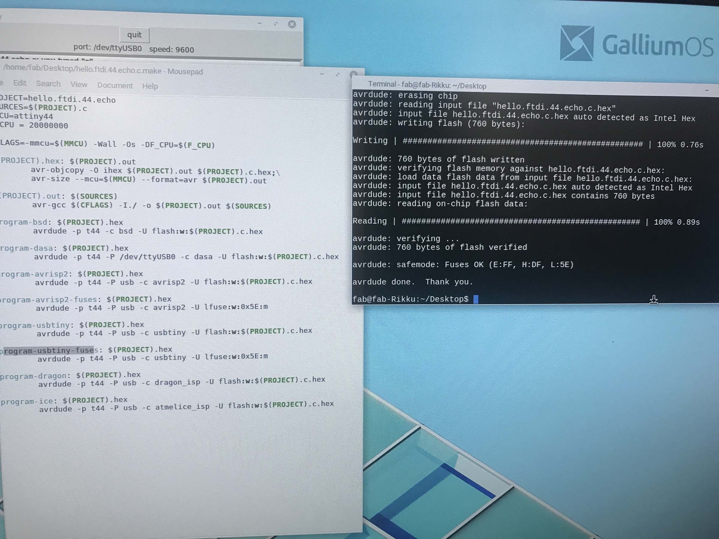
3. Programming

Figure 5. FTDI wired up
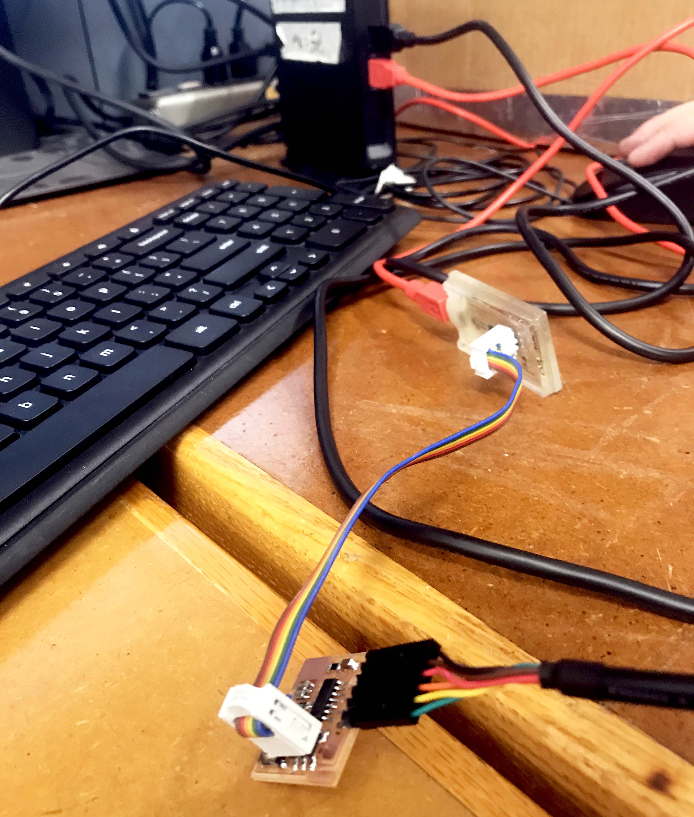
Figure 6. FTDI and programming board attached and connected to computer
After a minor microscoping inspection and some cleaning up the board was complete! The connections were set up and the files downloaded. It took me some reading and chatting with the TAs before this part became more clear. I look forward to revisiting this as I feel this is the part that gets really exciting!