Danielle Aspitz
MAS.863 | How to Make (Almost) Anything
Embedded Programming
Getting my LED to turn on using the button
_1. Programming
2. Uploading via Terminal
3. Uploading via Arduino
_
1. Programming
This week the goal was to program the board we made a few weeks ago.
I definitely struggled to understand all the components required to get this week's assignment done. After lots of reading past websites and consulting with TAs I finally got the gist of what was needed. First we needed both boards we had made, the FabtinyISP is used to program and the Echo Hello board receives the program. Next we need to plug in both boards, so an FTDI to USB connector and a USB port to USB adapter and finally the ISP header ribbon that connects the two boards.
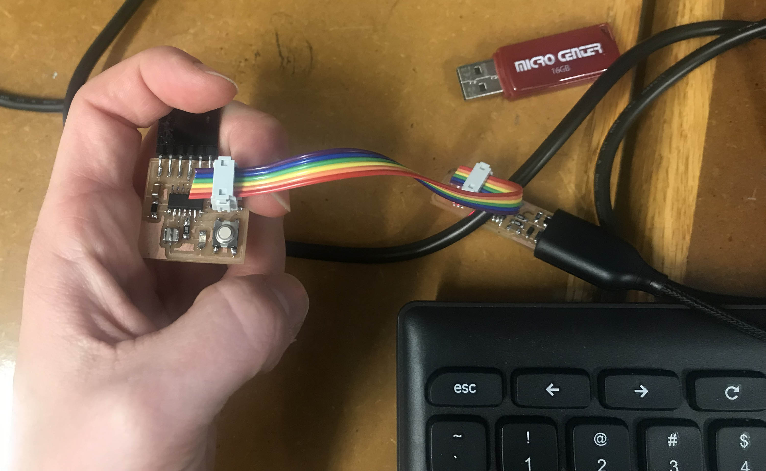
Figure 1. All wired up
Next we needed to download and install the AVR libraries into the terminal. I tried to do this through a download called CrossPack-AVR, but unfortunately this didn't work. I also tried through Homebrew and this too did not work. Finally I moved over to the FabLab computer which had these programs installed and simply skipped this step. Next I read through the Atmel Data Sheet to find the proper terminology for which pins my LED and button were connected to.
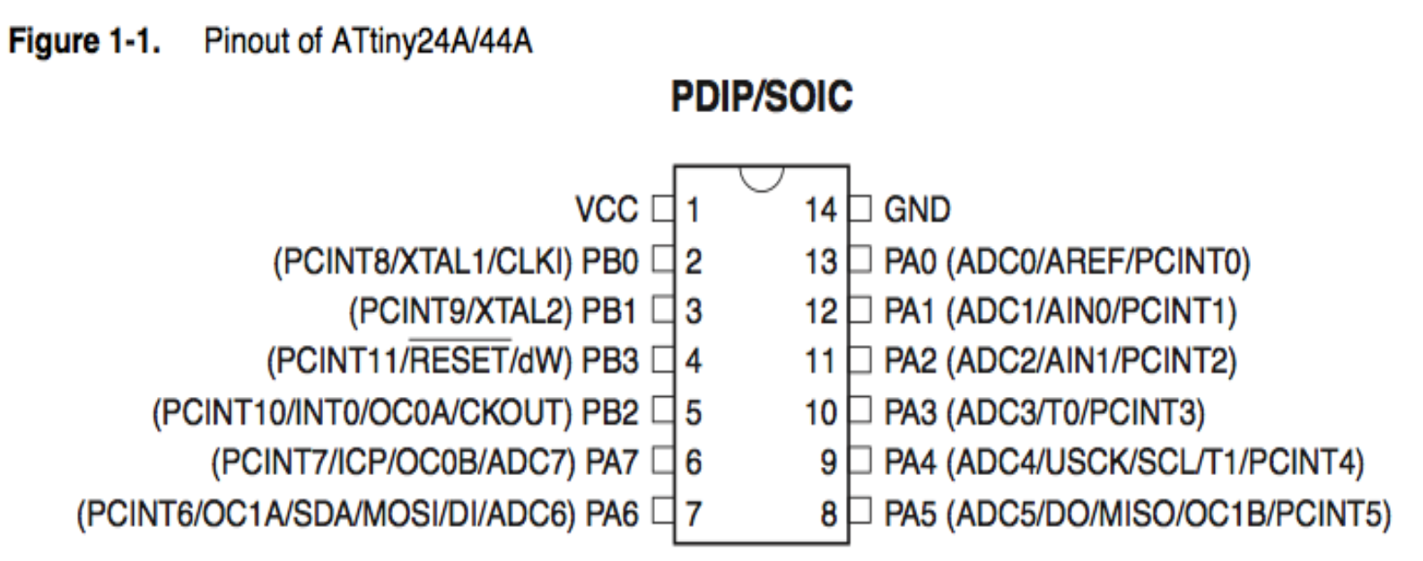
Figure 2. Pinout Diagram
I read through Rob's tutorial and chose to use the last version to test. I downloaded the .c and .make files and edited the two values for my pinout formation. I had my LED in PB2 and my button in PA.
2. Uploading via Terminal
Next you open up your terminal and type in make -f button.make to get your hex file. If you now see the .hex file in your folder than you can move to the next step. Type in: make -f button.make program-usbtiny This should successfully program your board.
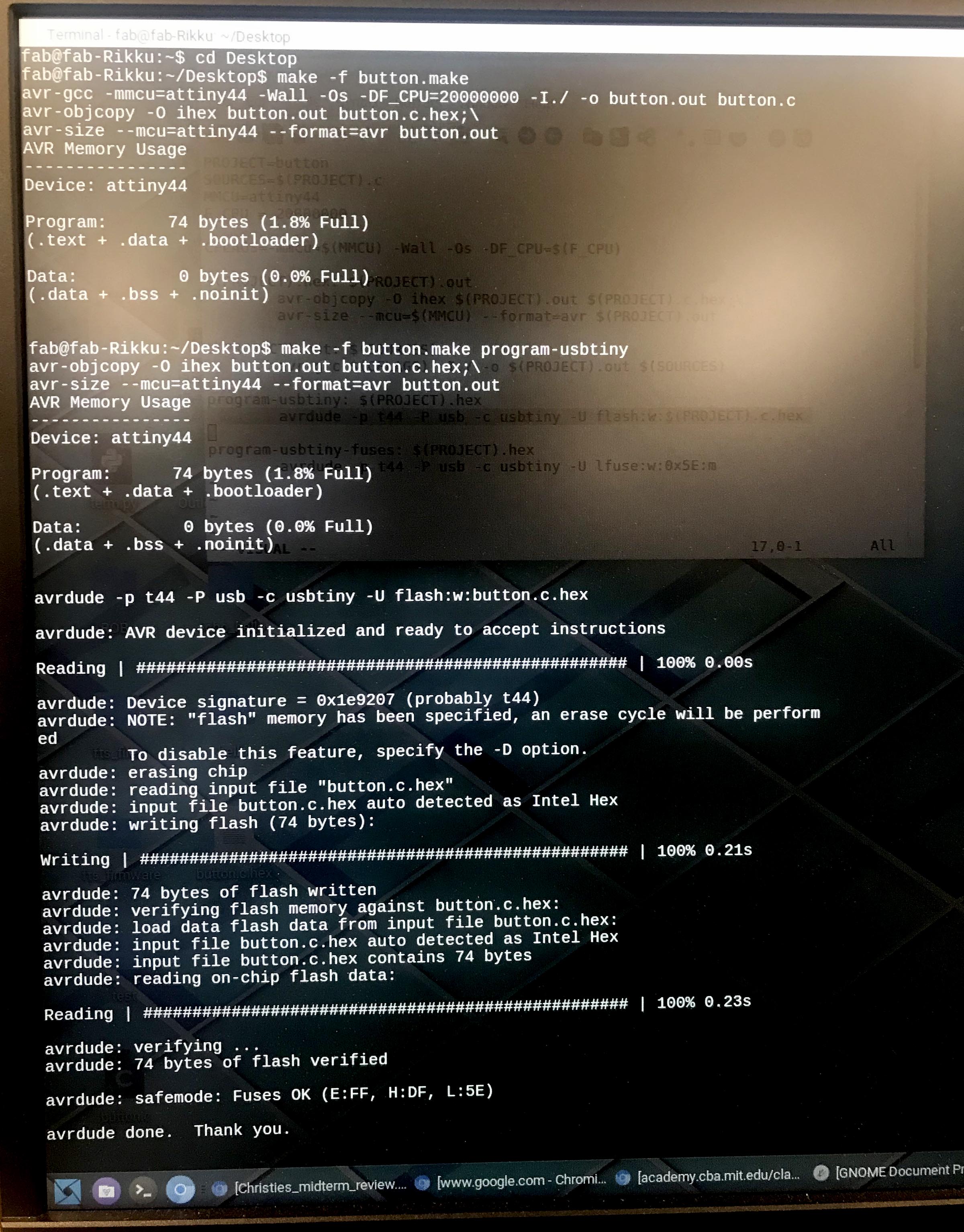
Figure 3. Script within terminal
Figure 4. It works!
DISCLAIMER: It actually did not work my first time and after much agonizing frustration I walked away, and came back the next day, calm. I tested the voltages on the board, it looked like everything was working EXCEPT the connection between the pin and the resistor leading to the LED. I think because the traces were so small this trace came up and was not creating an electrical connection. Rob suggested I create a solder bridge to recreate this connection. This worked! Thankfully I did not have to remake my board, and the script was correct.
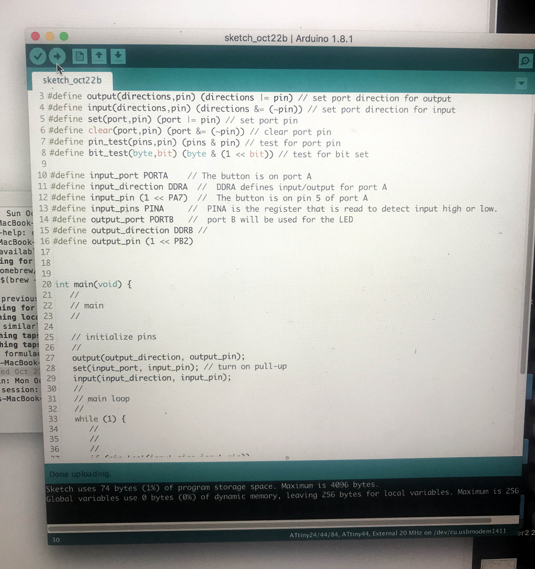
2. Uploading via Arduino
Arduino is much more intuitive. After installing the software I simply opened up a new sketch and copied Rob's code into the sketch file. I clicked verify, and the code appeared to be correct, then I clicked upload. I actually got an error the first few times but after reading a bit online it seemed to be that the computer was not recognizing the USB port data. I unplugged and re-plugged everything a few times until finally it worked!