Danielle Aspitz
MAS.863 | How to Make (Almost) Anything
Computer-Controlled Machining
Bookcase turned wall art
_1. Modeling
2. Preparing Cut File
3. Programming
4. Cutting
5. Assembling
_
1. Modeling
This week we were assigned to make something big.
I went through a number of designs for this project, first landing on a leaning bookshelf which is something I've dreamed about having for months now. Ultimately upon designing this I felt it was too simple/linear and that CNC was not the appropriate method to fabricate this piece. In this train of thought I designed a piece which could virtually only be done with a CNC. A parametrically-designed modular assembly of an undulating wall piece.
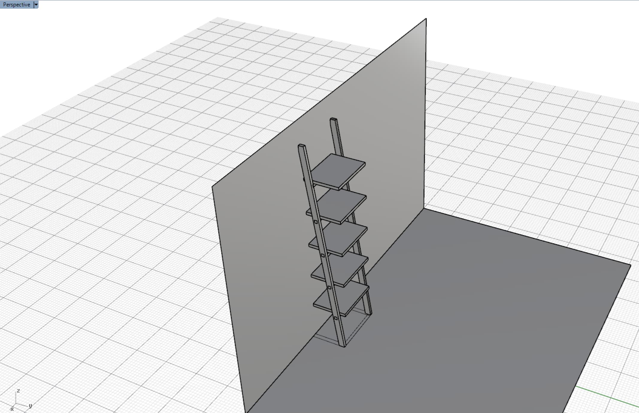
Figure 1. Bookshelf Model
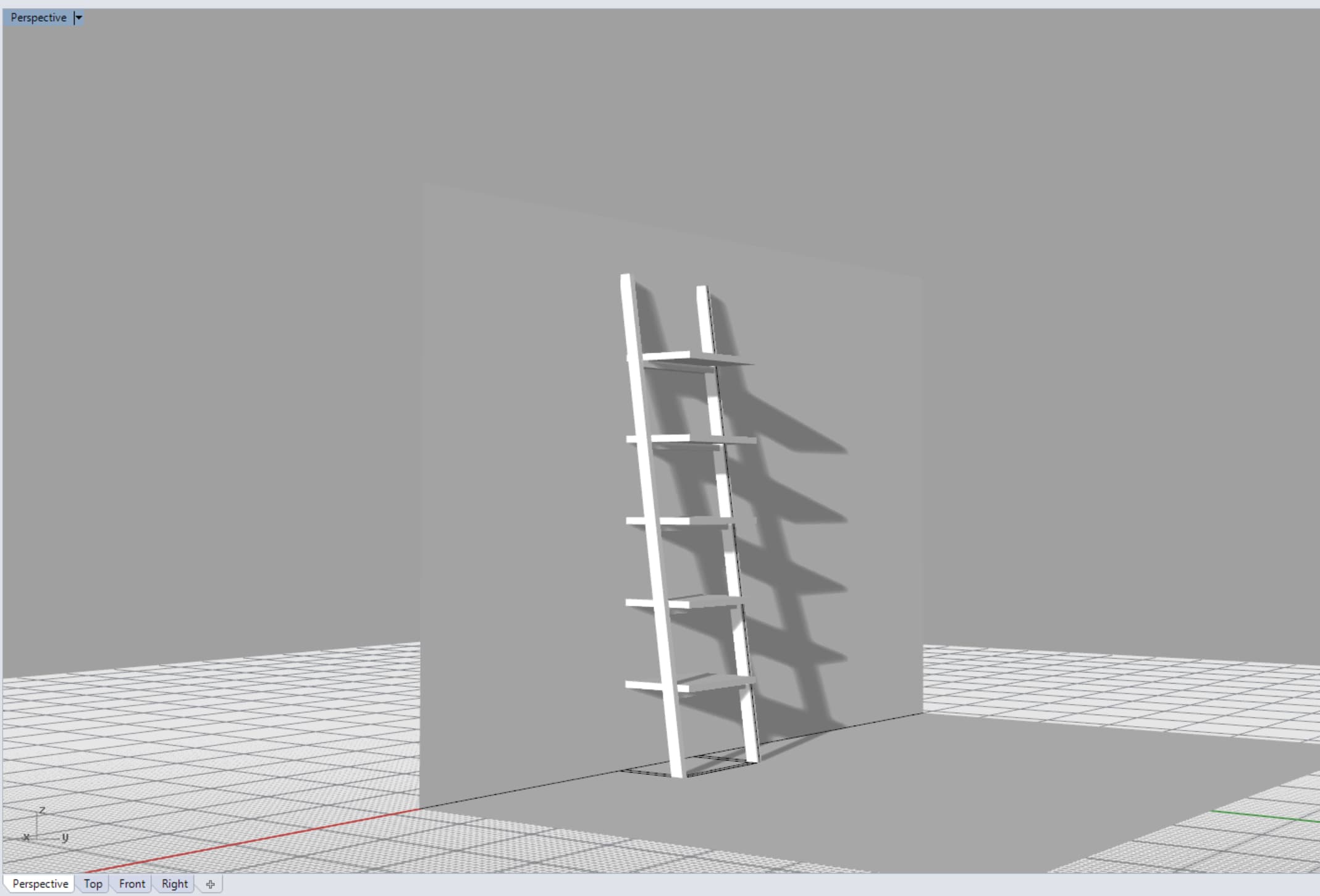
Figure 2. Rendered Bookshelf
My new design took a lofted surface working off the energy within the corner of the room and fragments it into triangular modules with apertures expanding towards the window. The idea was to play with modules, undulating form, and a gradient of apertures.
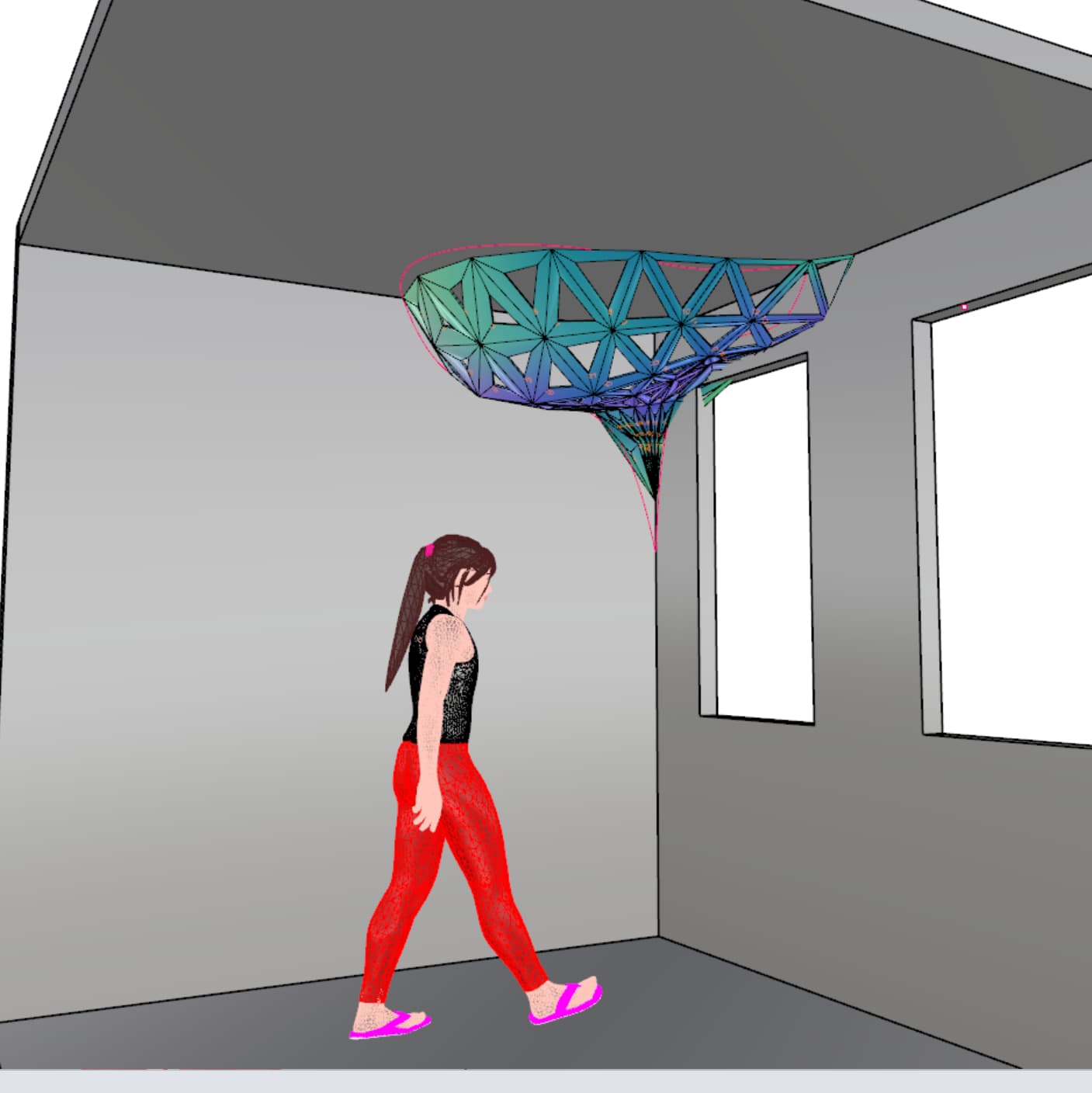
Figure 3. Wall installation
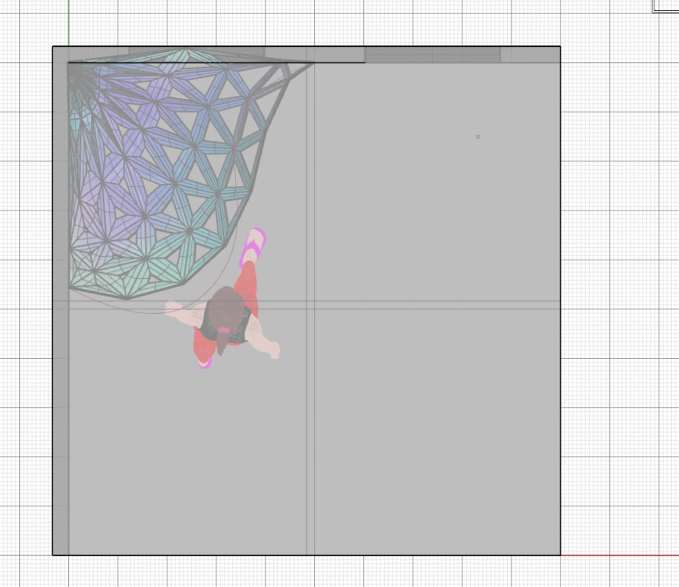
Figure 4. Top View
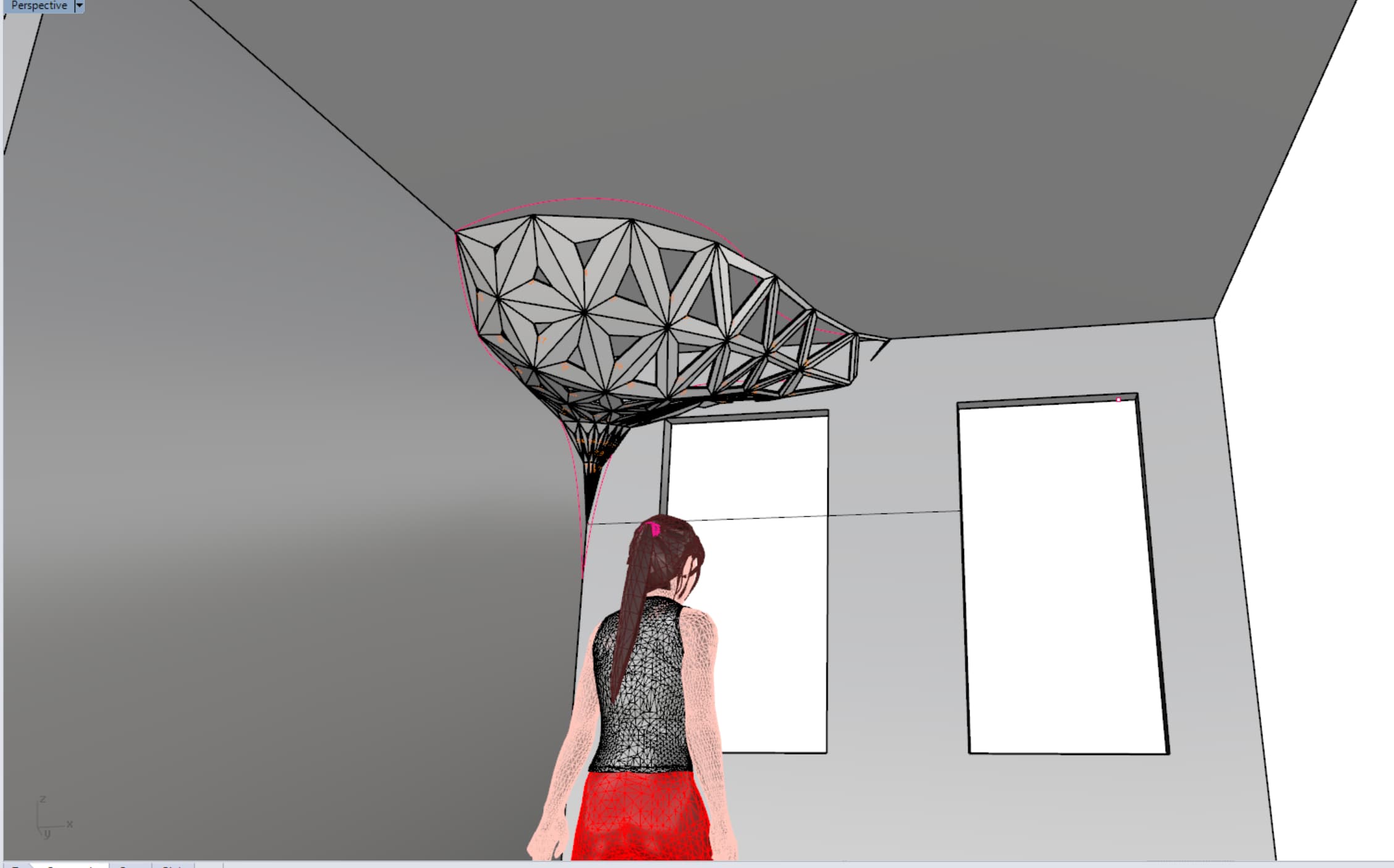
Figure 5. Looking up
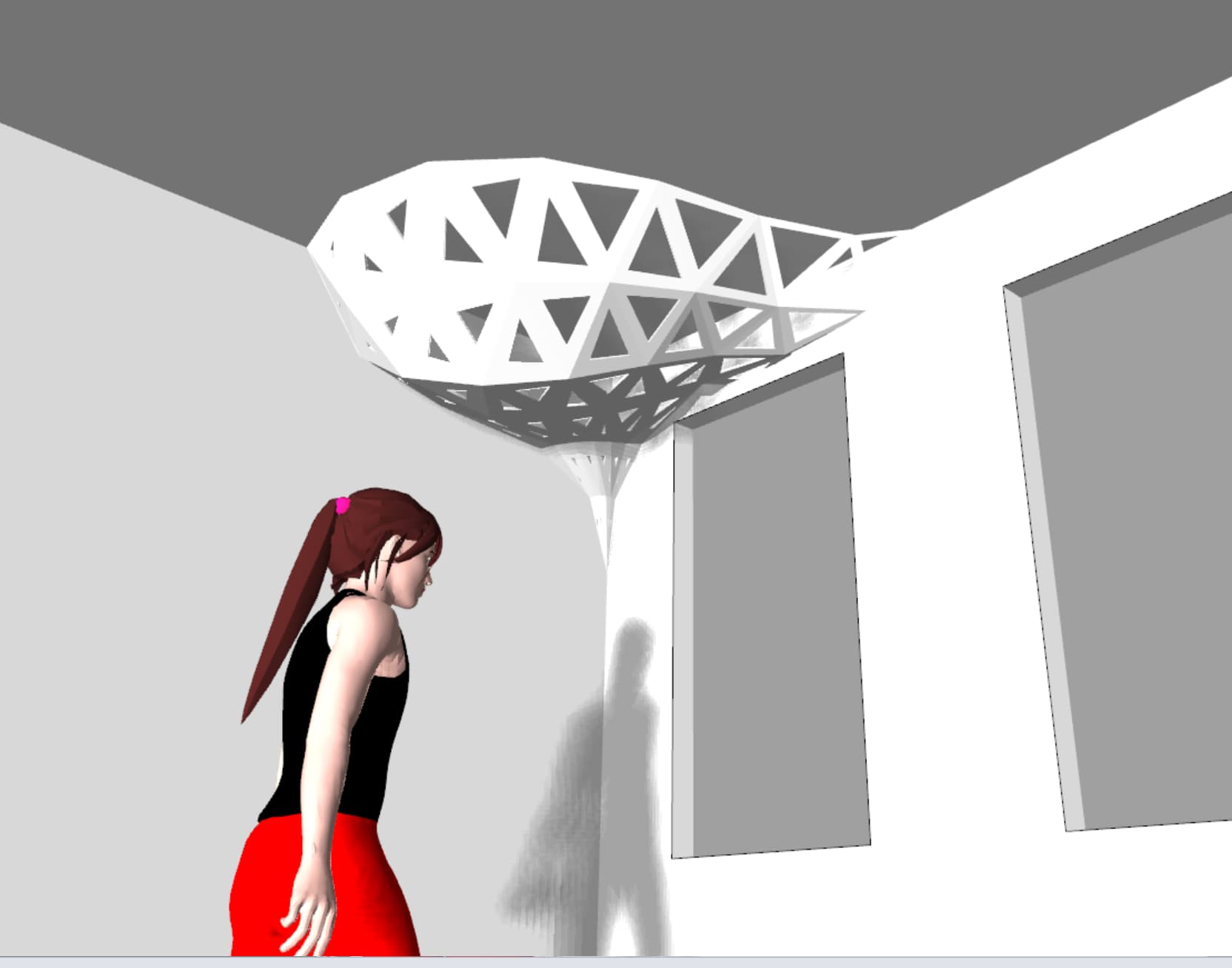
Figure 6. Rendered View
2. Preparing Cut File
Originally I laid out all the pieces according to which edges would be beveled for the connecting joints. This involved a long process of exploding the mesh, converting to NURBS, lofting surfaces, rotating depending on which side was being beveled than selecting containment curves for beveled edges. After doing all this I was told thees regions were likely too small to be super noticeable. I considered this and also feedback from friends whom upon seeing the file kept thinking the shapes were three dimensional and beind dissappointed when I told them they were flat panels I ultimately scrapped the bevelling, re-rotated all shapes to be face up and re-modelled the forms so there was a slight slope assending toward the aperture of each module. The material I had was only 3/8" thick so I decided to slope the surface for 1/4" and leave 1/8" for connections.
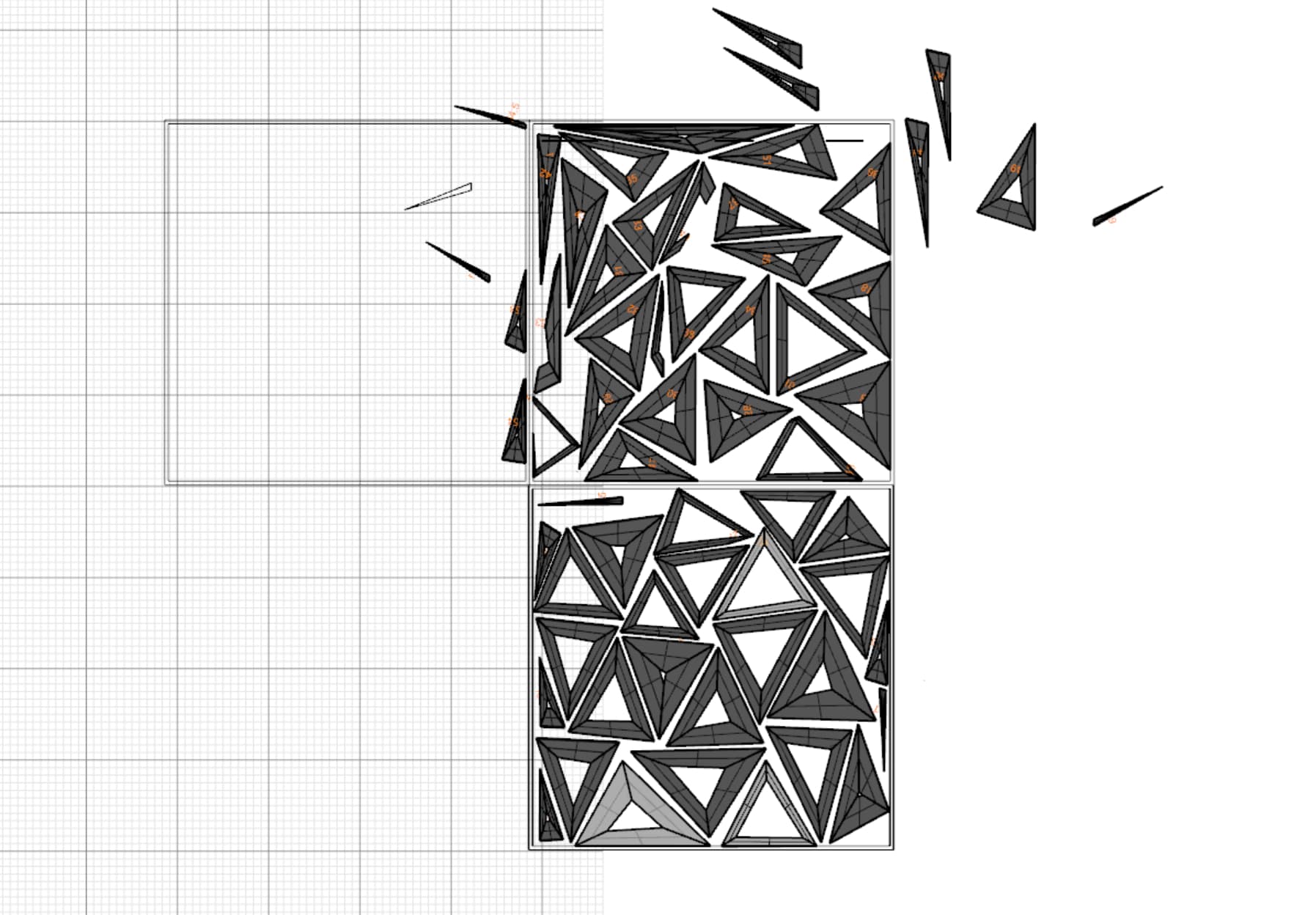
Figure 7. All modules laid out
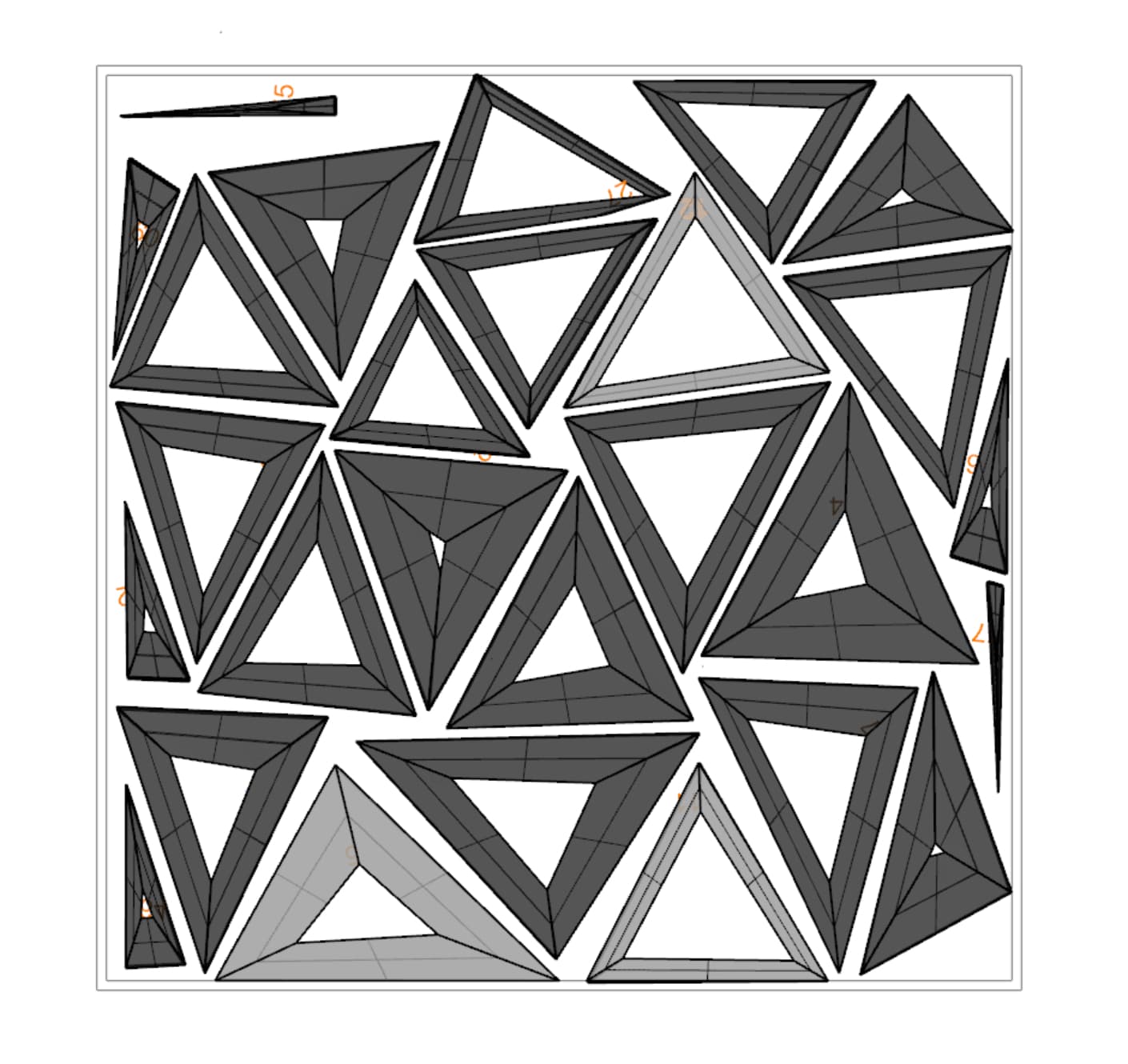
Figure 8. First 4'x4' sheet
3. Programming
Setting up the file in MasterCAM (what the GSD requires) took me ages (3 full days). This is due to the fact that MasterCAM has a STEEP learning curve, and that each time I submitted a new TA looked it over and had new comments and the file additionally crashed right before I was about to cut and we had to redo EVERYTHING. Quite a pain, but I do feel thoroughly conditioned now that I'm through with this experience.
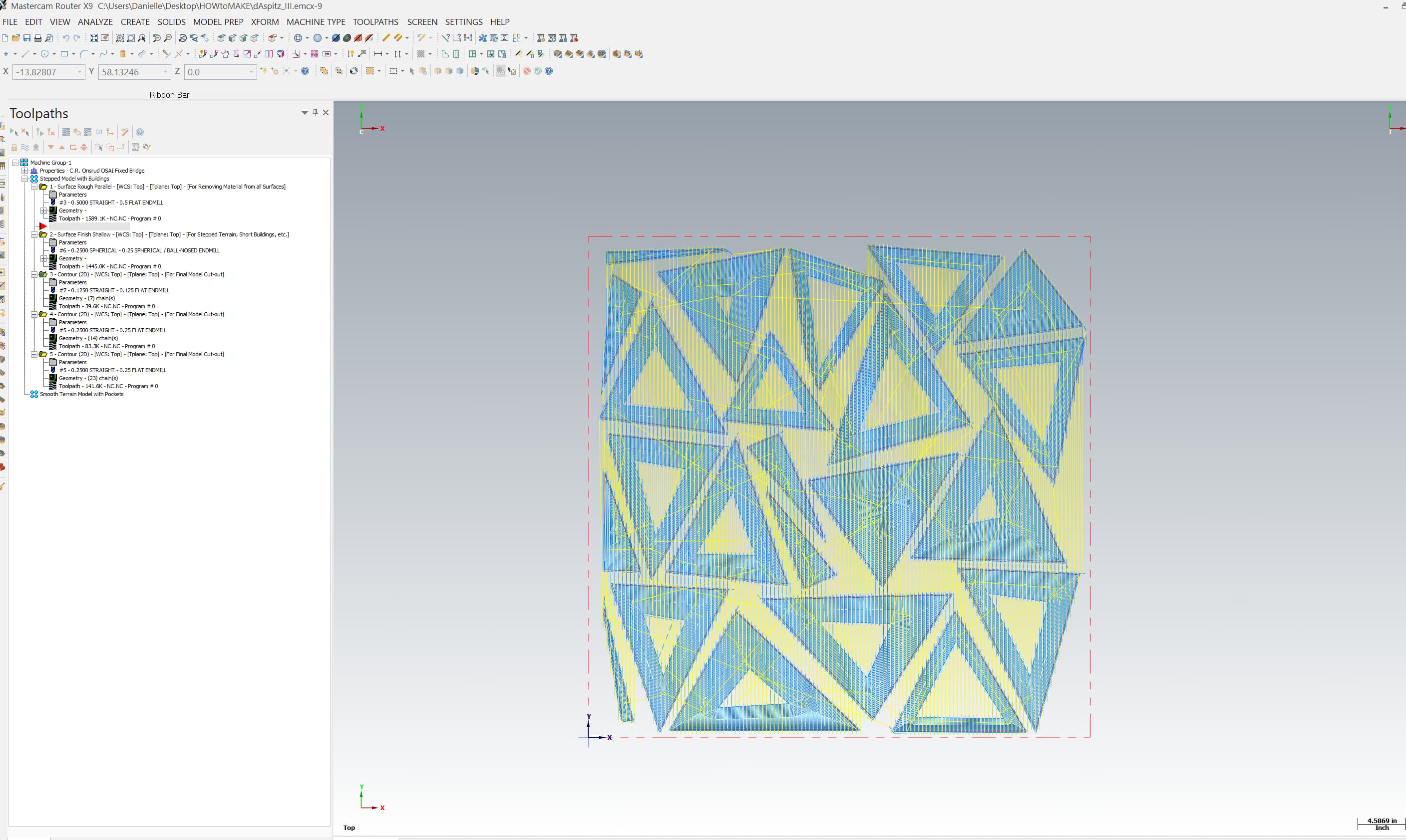
Figure 9. Roughing Pass
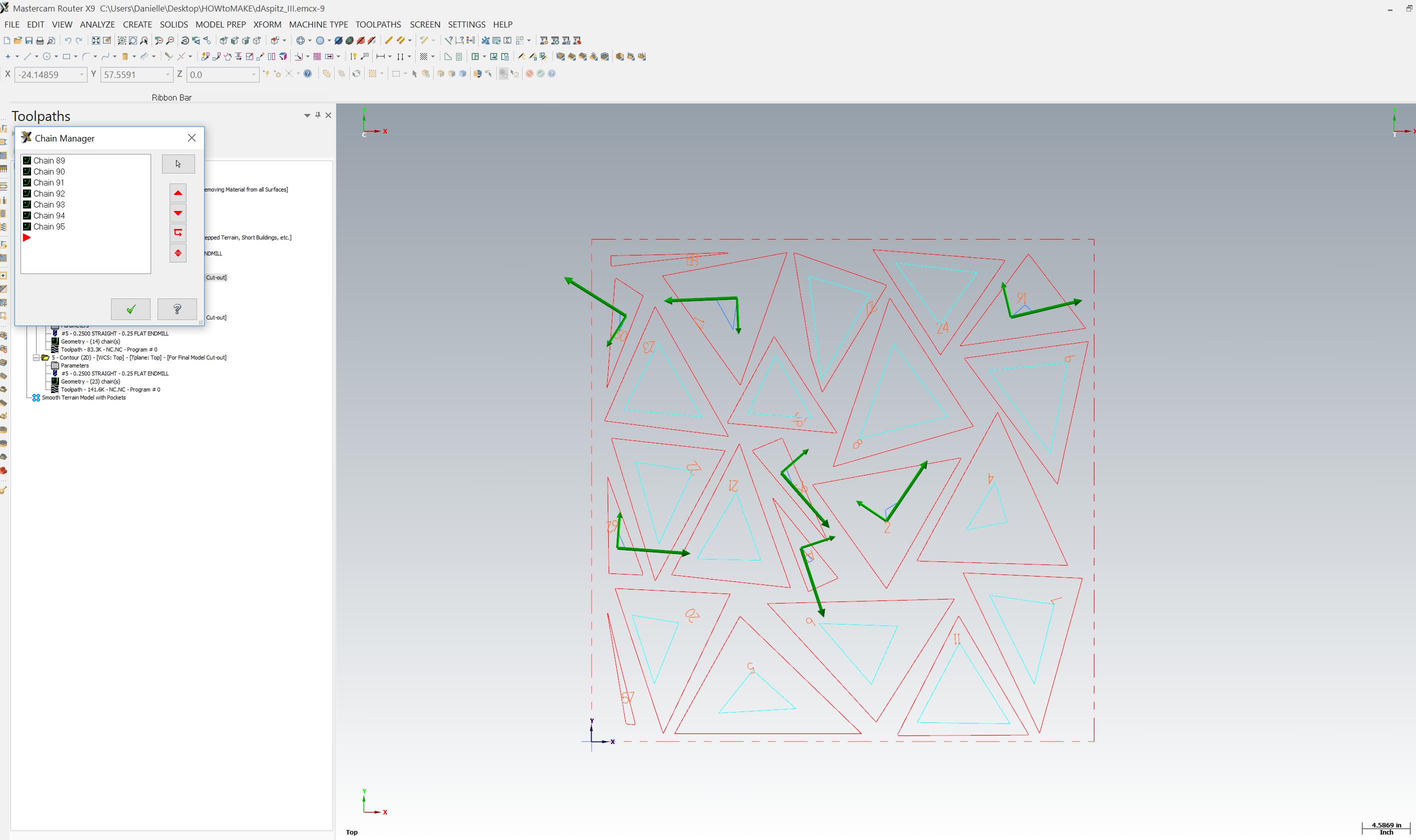
Figure 10. Smallest curves with 1/8" bit
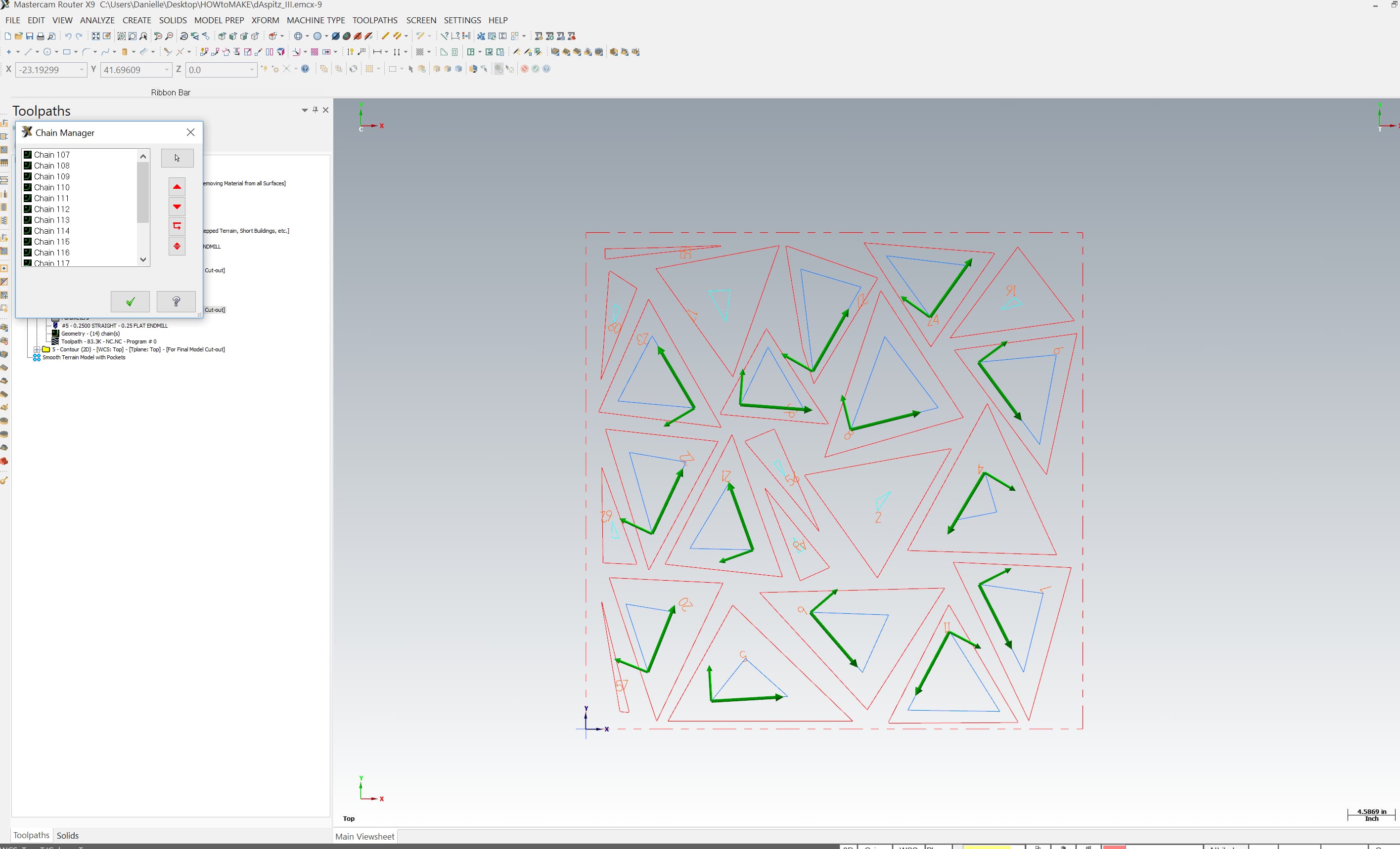
Figure 11. Larger curves with 1/4" bit
One TA noticed that because the starting point of the inner cut-outs was placed at the corners the lead in angle was actually cutting into the piece I wanted to keep. I realized this would be bad so I had to manually readjust every single start point for each chain on the inner curves.
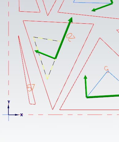
Figure 12. Readjusting starting point
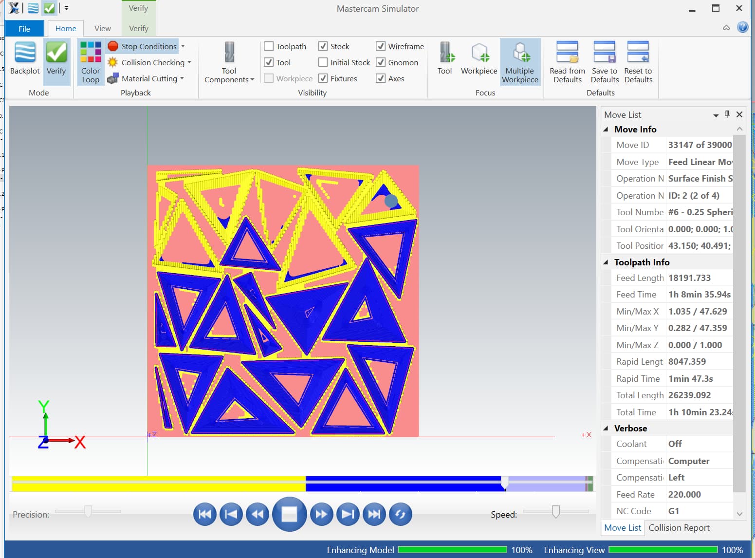
Figure 13. Simulation I
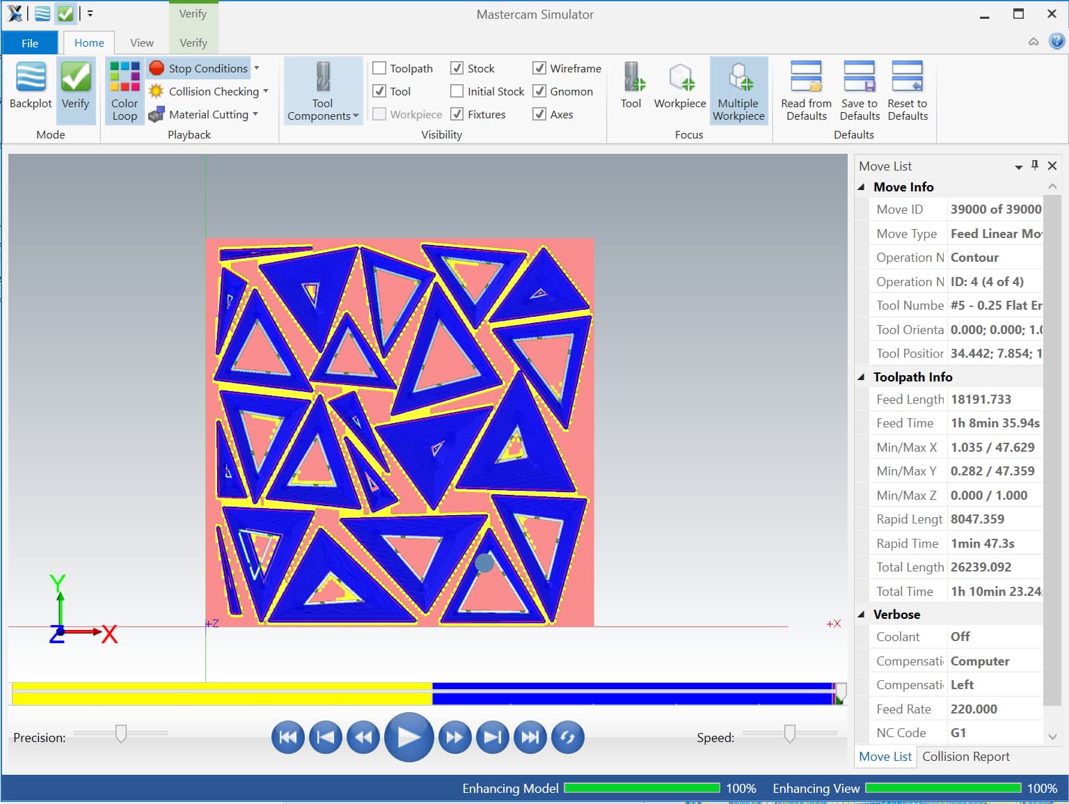
Figure 14. Simulation II
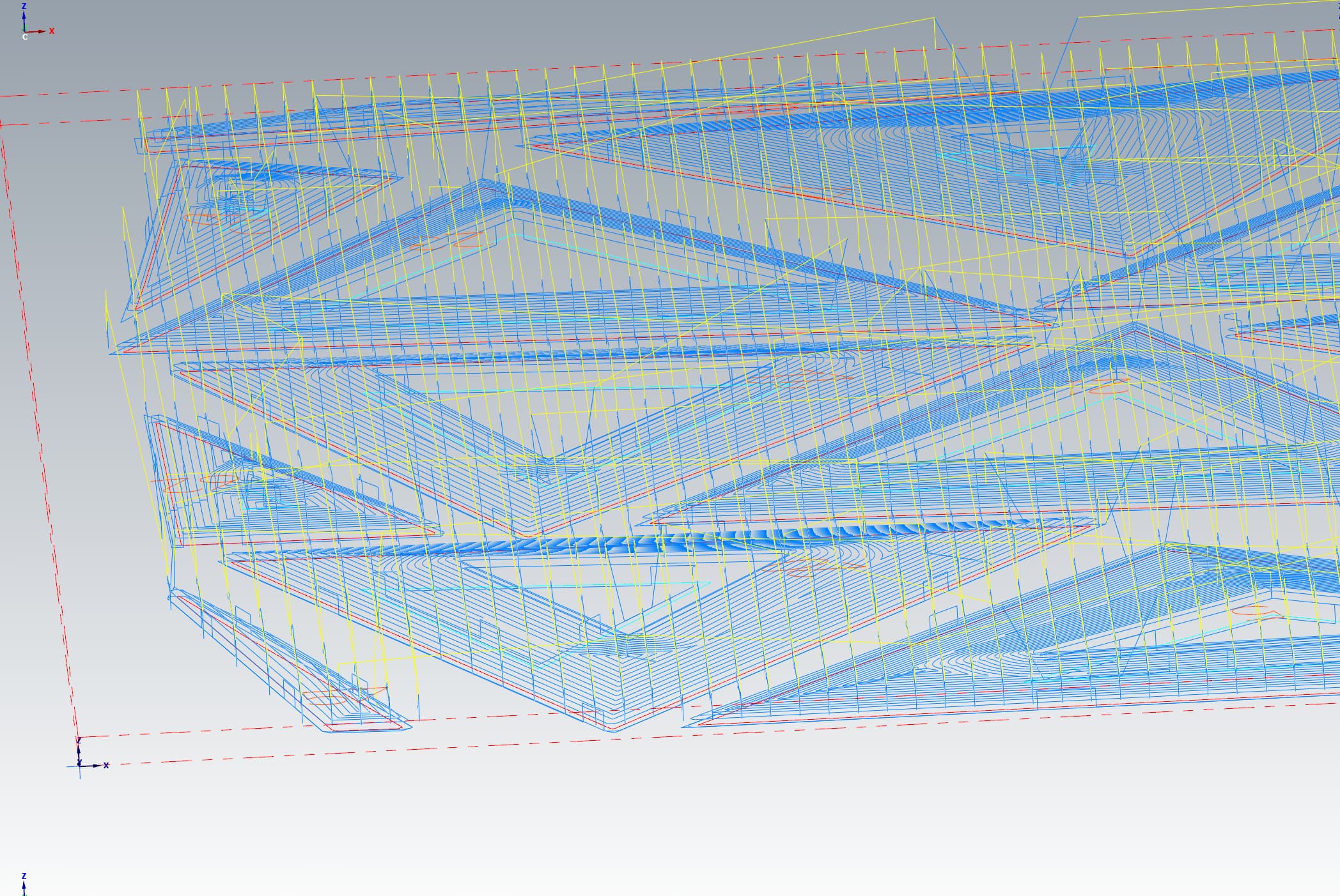
Figure 15. Detail of toolpaths
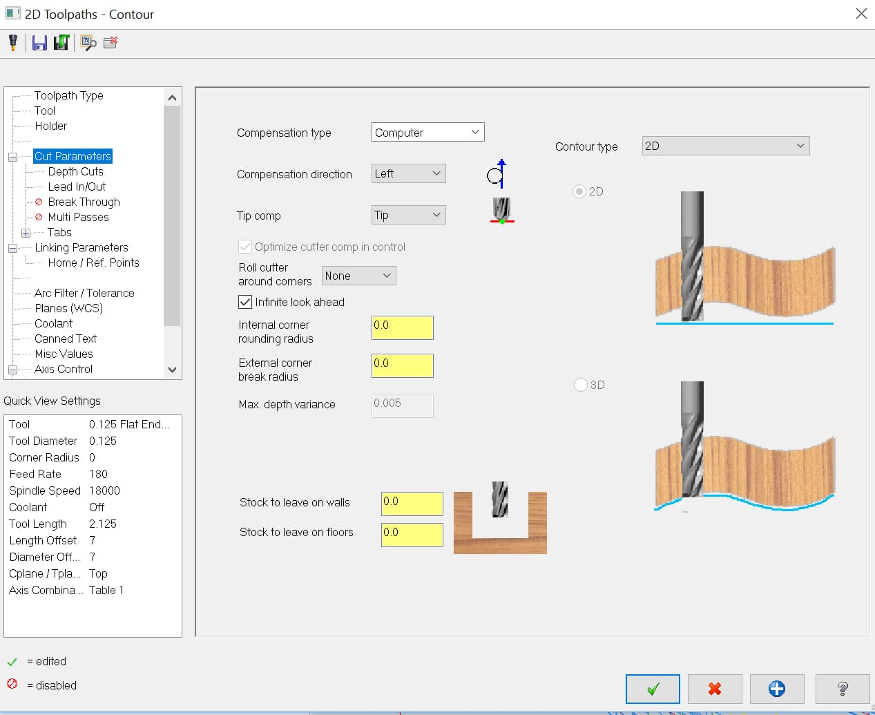
Figure 16. Tool parameter: "inside/outside" cut labelled as "left/right"
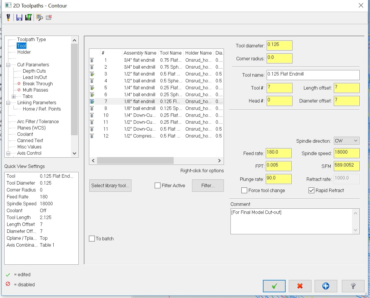
Figure 17. Tool parameter: Selecting tool from GSD Fab Lab library
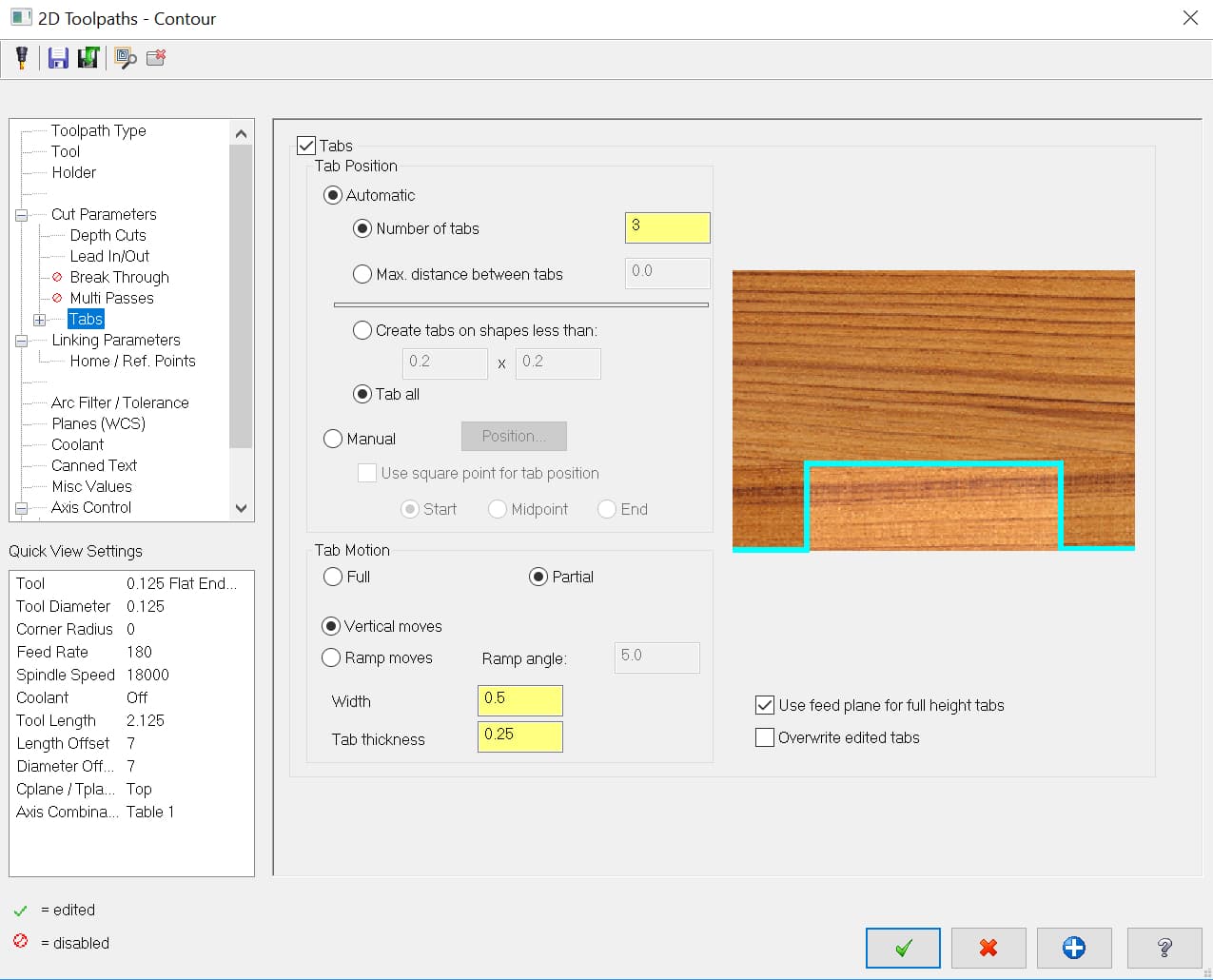
Figure 18. Tool parameter: Auto-tab, which we forgot to re-adjust heights after file crashed
4. Cutting
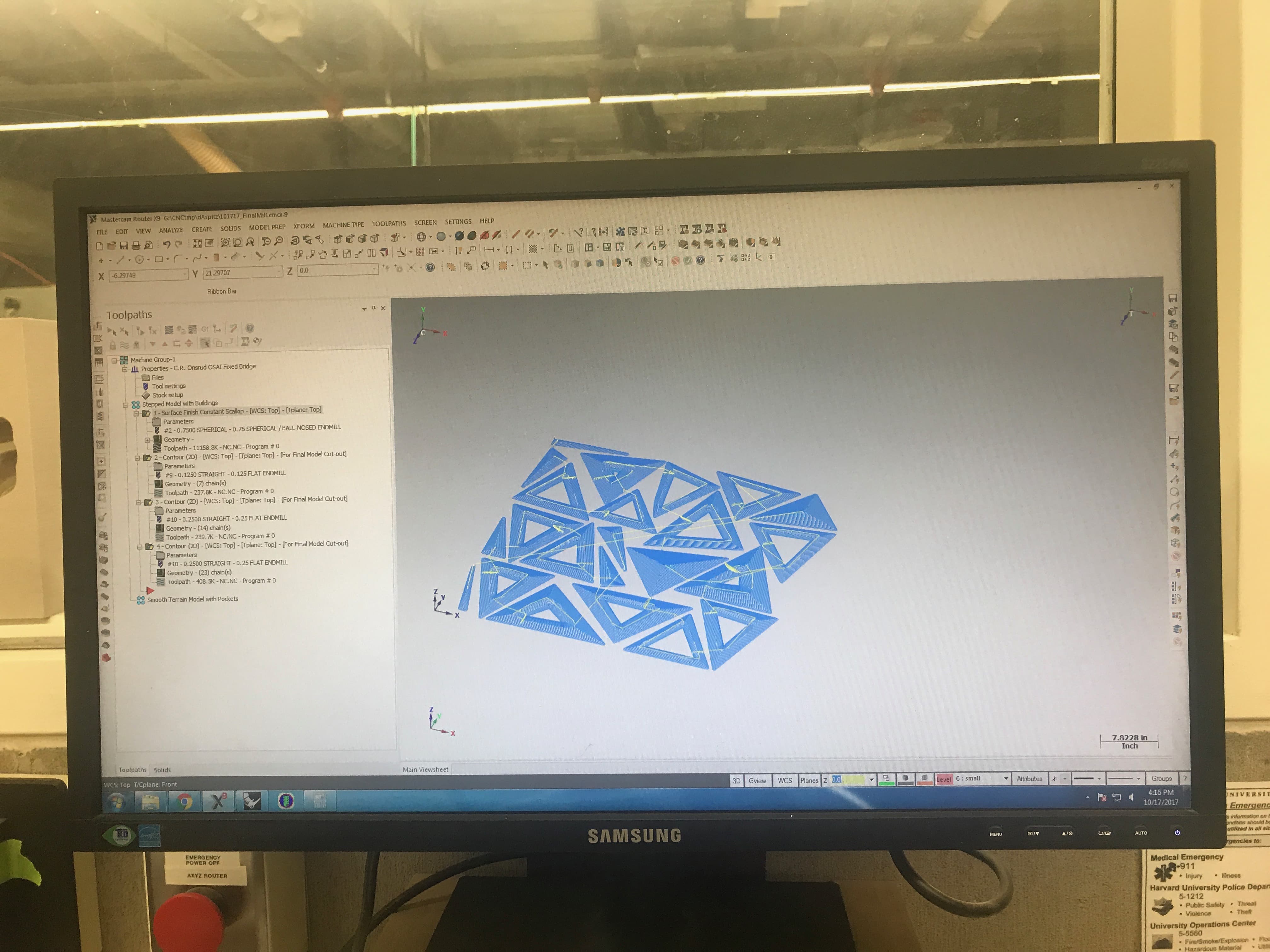
Figure 19. File finally ready to be posted!
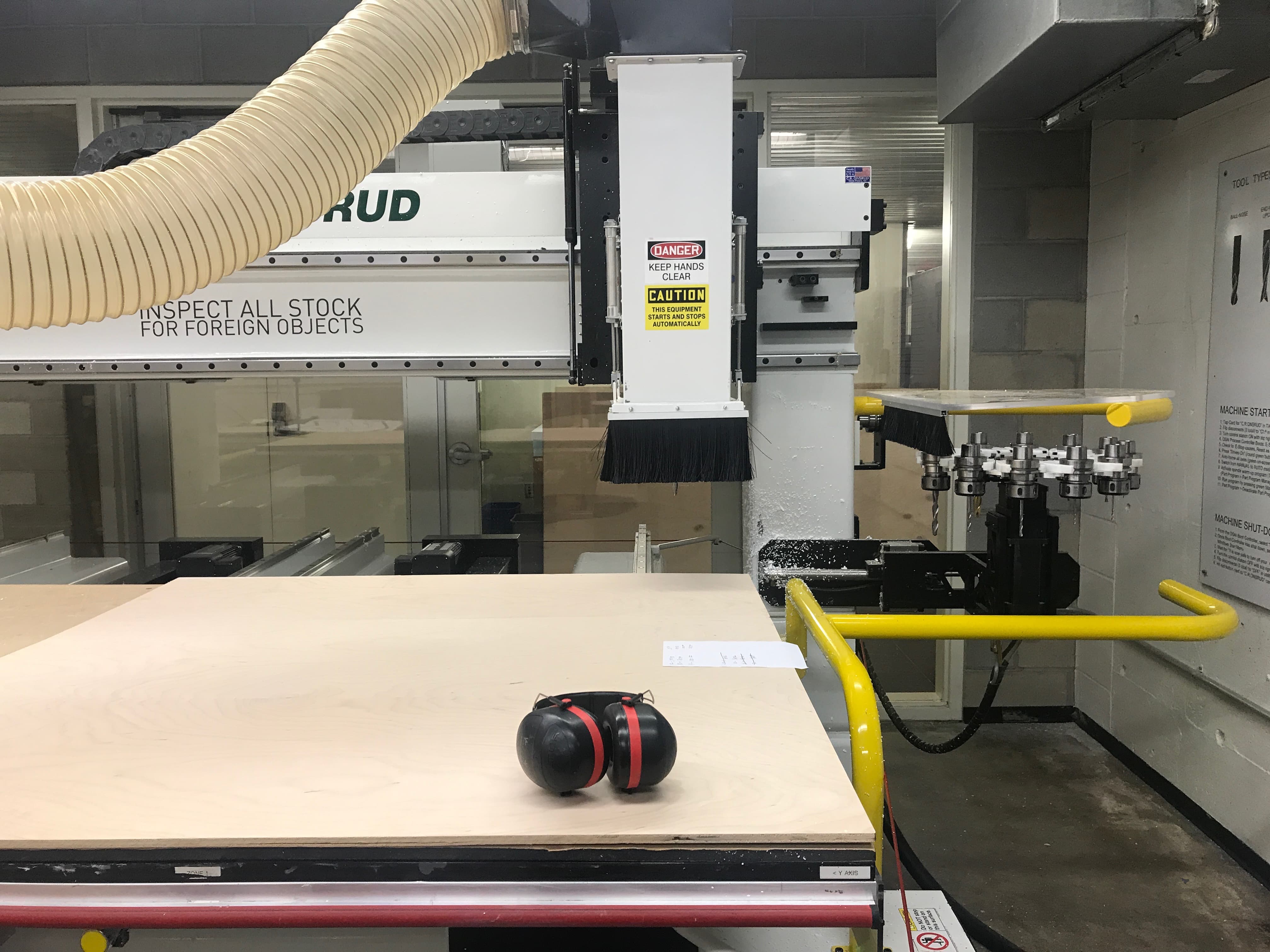
Figure 20. Setting up wood, luckily the bed is a vacuum bed so there is no need for screws
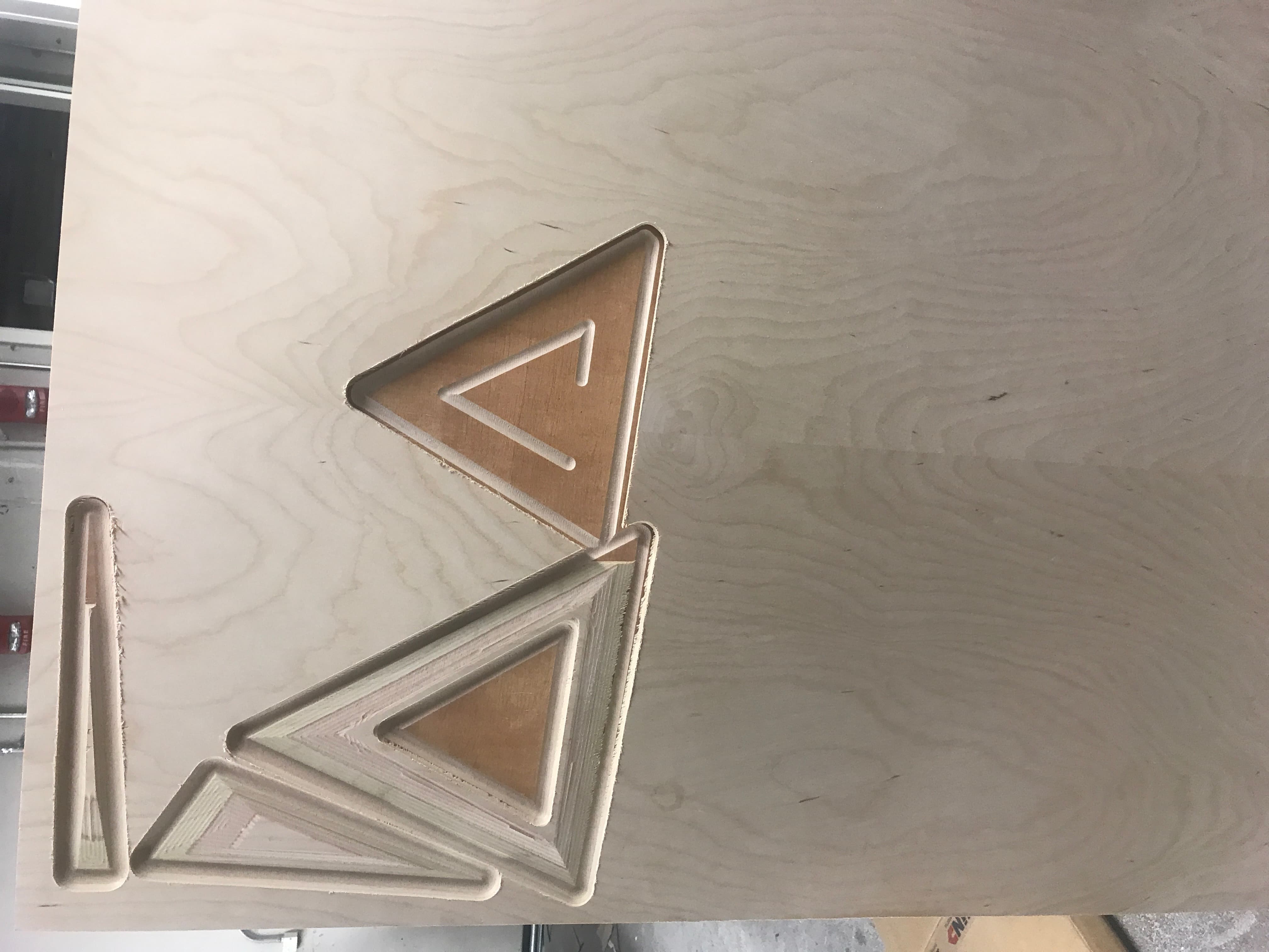
Figure 21. Unluckily this meant when the cheap wood I picked up had a huge air pocket we could not screw it down and keep cutting
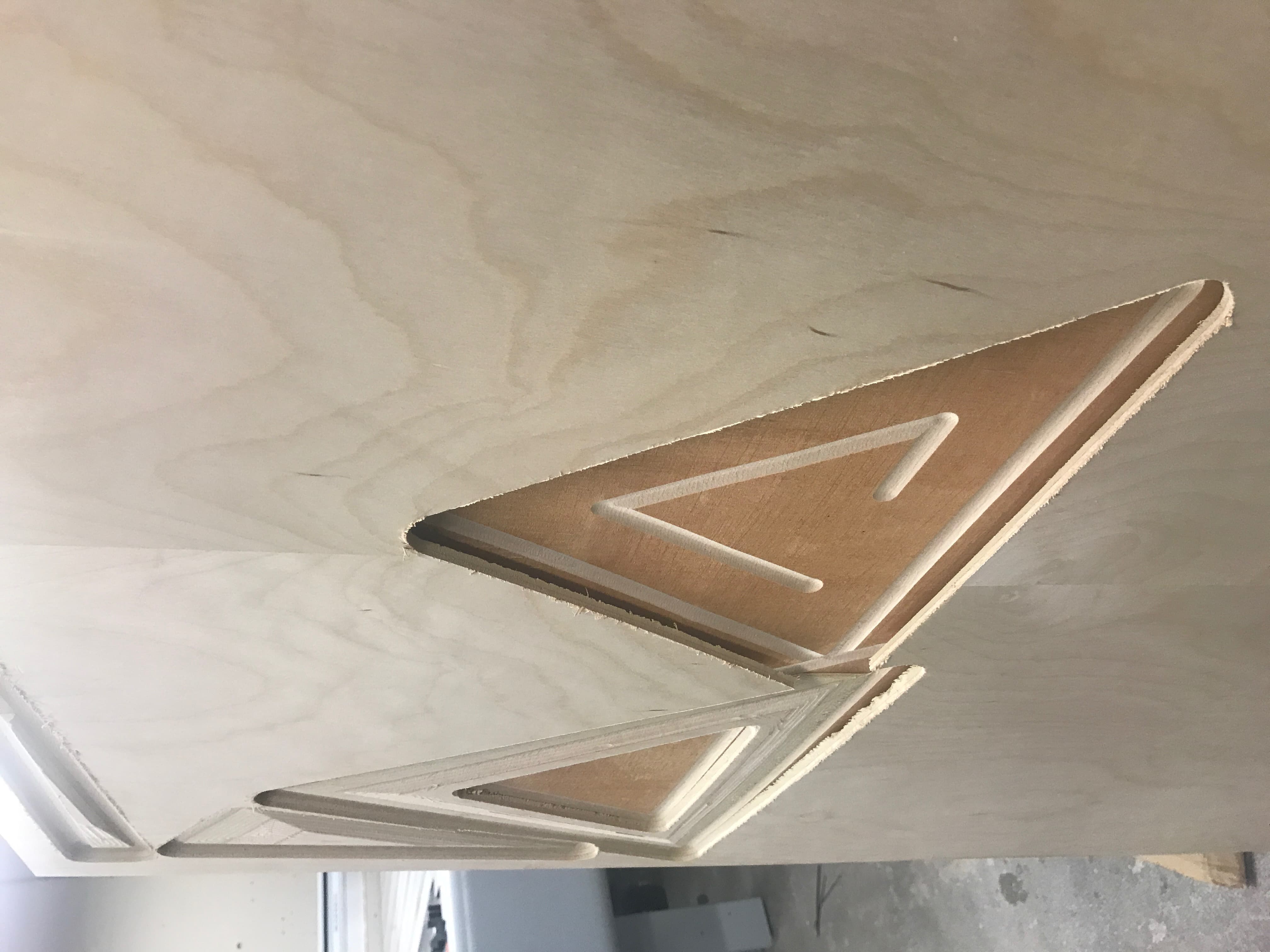
Figure 22. Fortunately I had another spare sheet because this one was dangerous to the machine and simply unusable
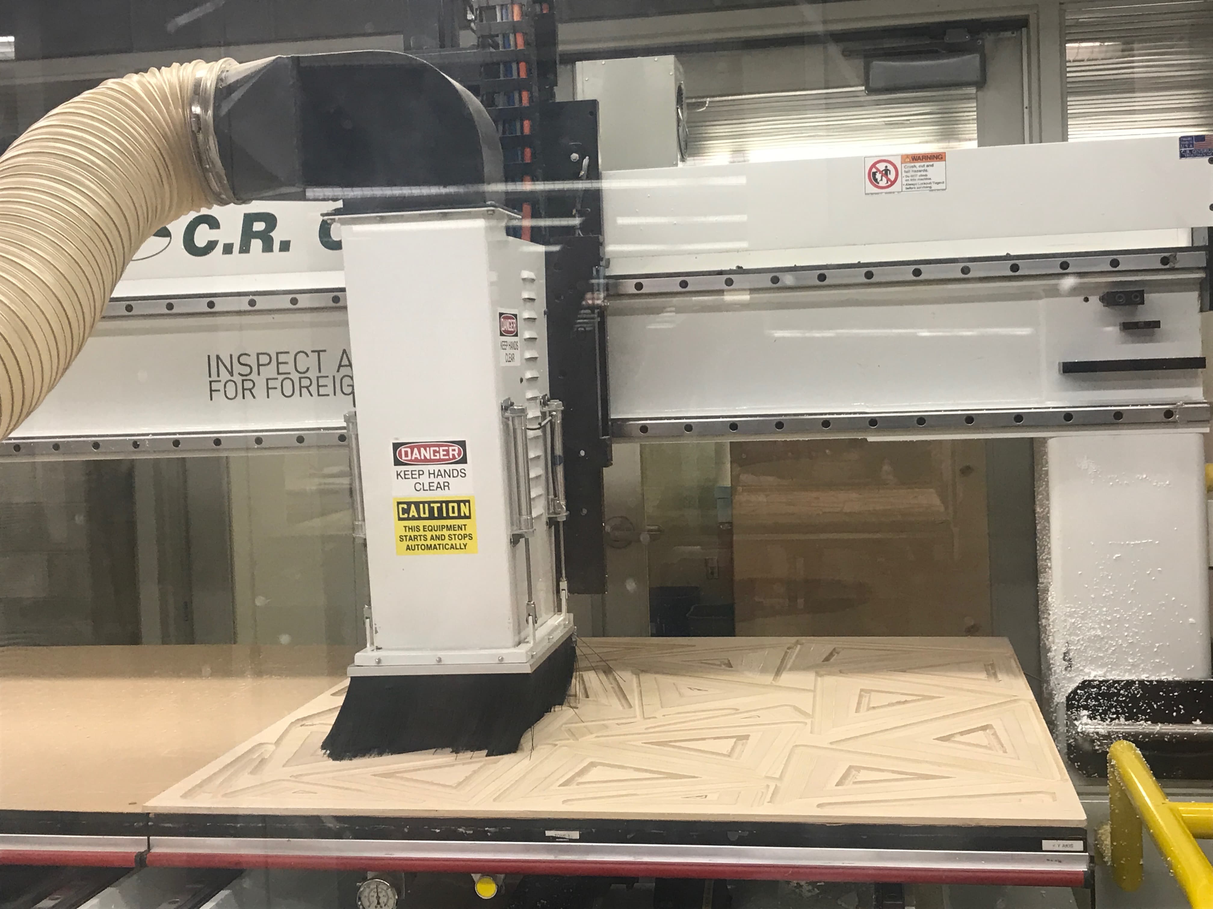
Figure 23. Take II was working!
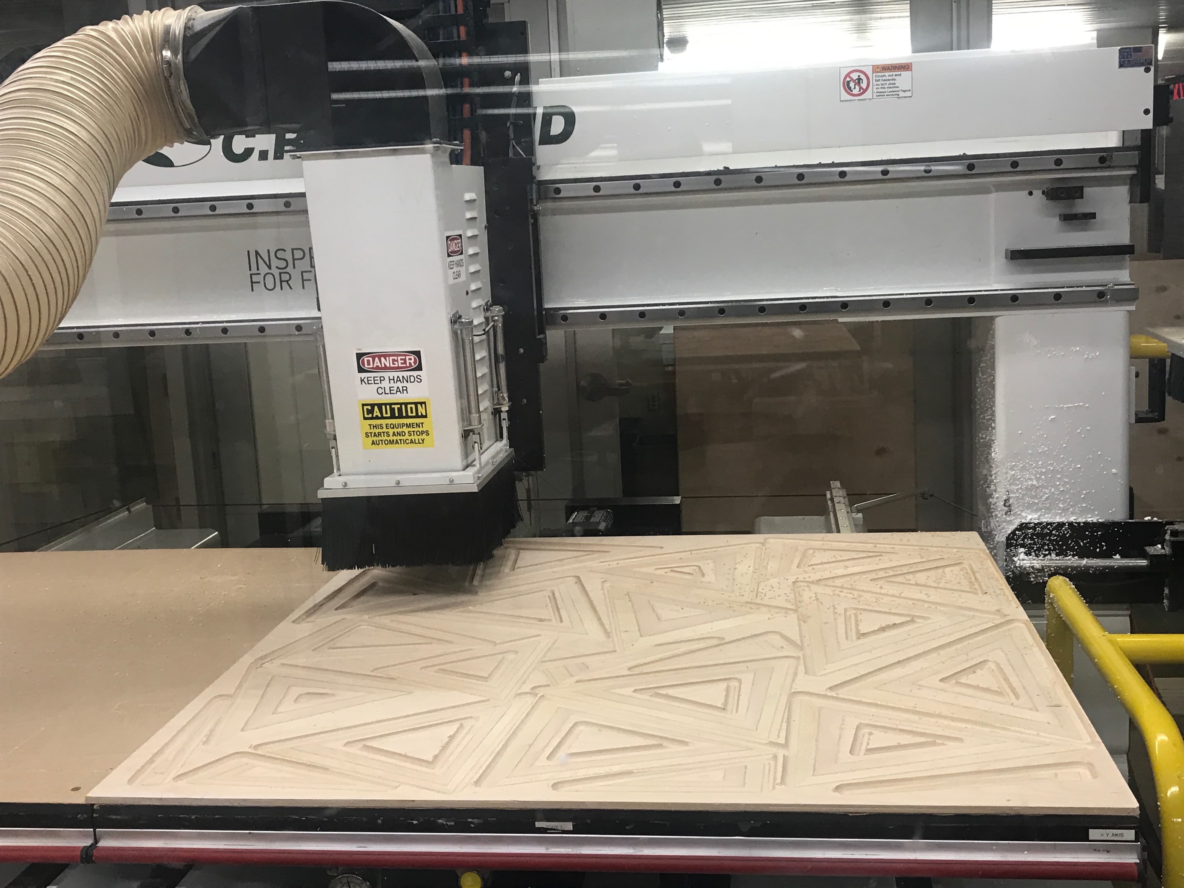
Figure 24. Shapes coming through
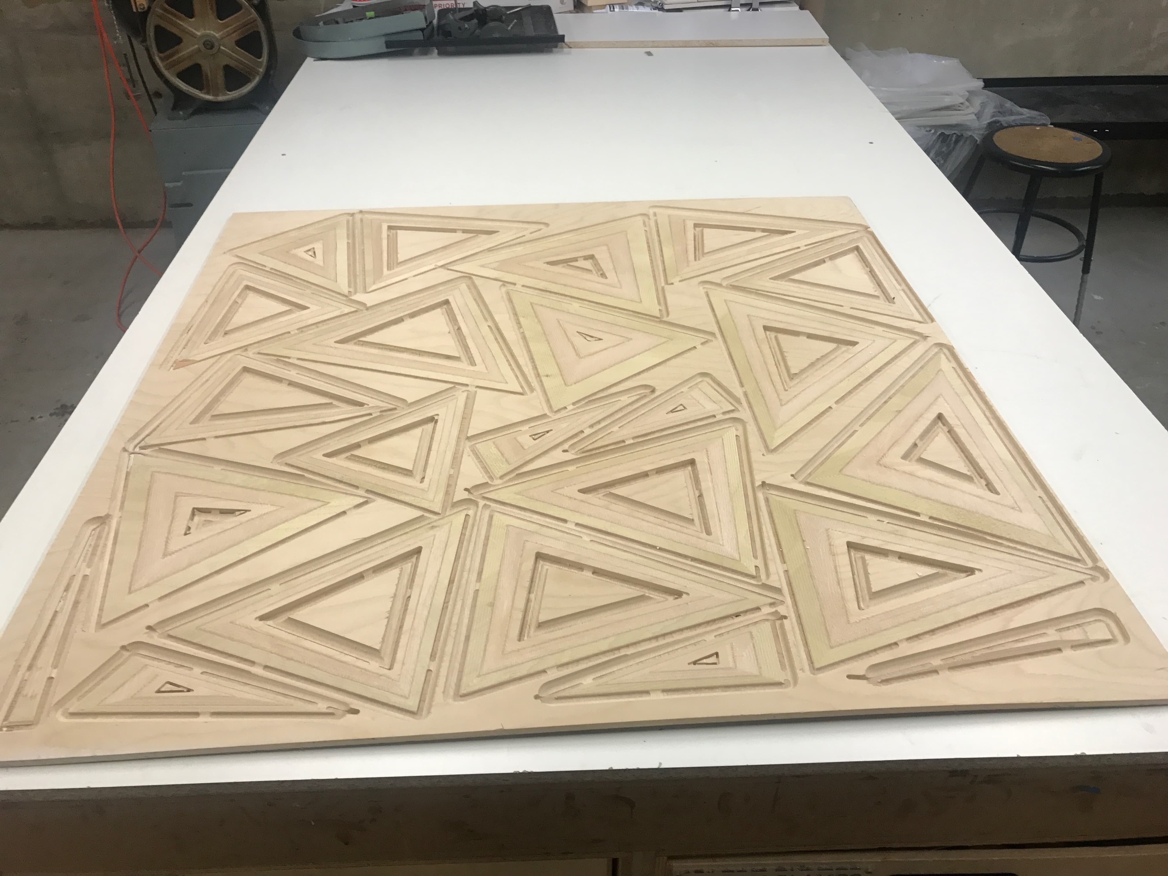
Figure 24. The pieces did not cut all the way through, but the machining was done!
5. Assembling
There was a fair deal of post-processing involved, and could have been done even more rigorously, but I was in a time crunch and simply wanted a proof of concept level of finish. The tab mistake resulted in thick tabs which were a challenge to remove, and the depth must not have been set with enough excess because a thin layer kept all the pieces from coming apart and had to be cut out one by one - quite frustrating.
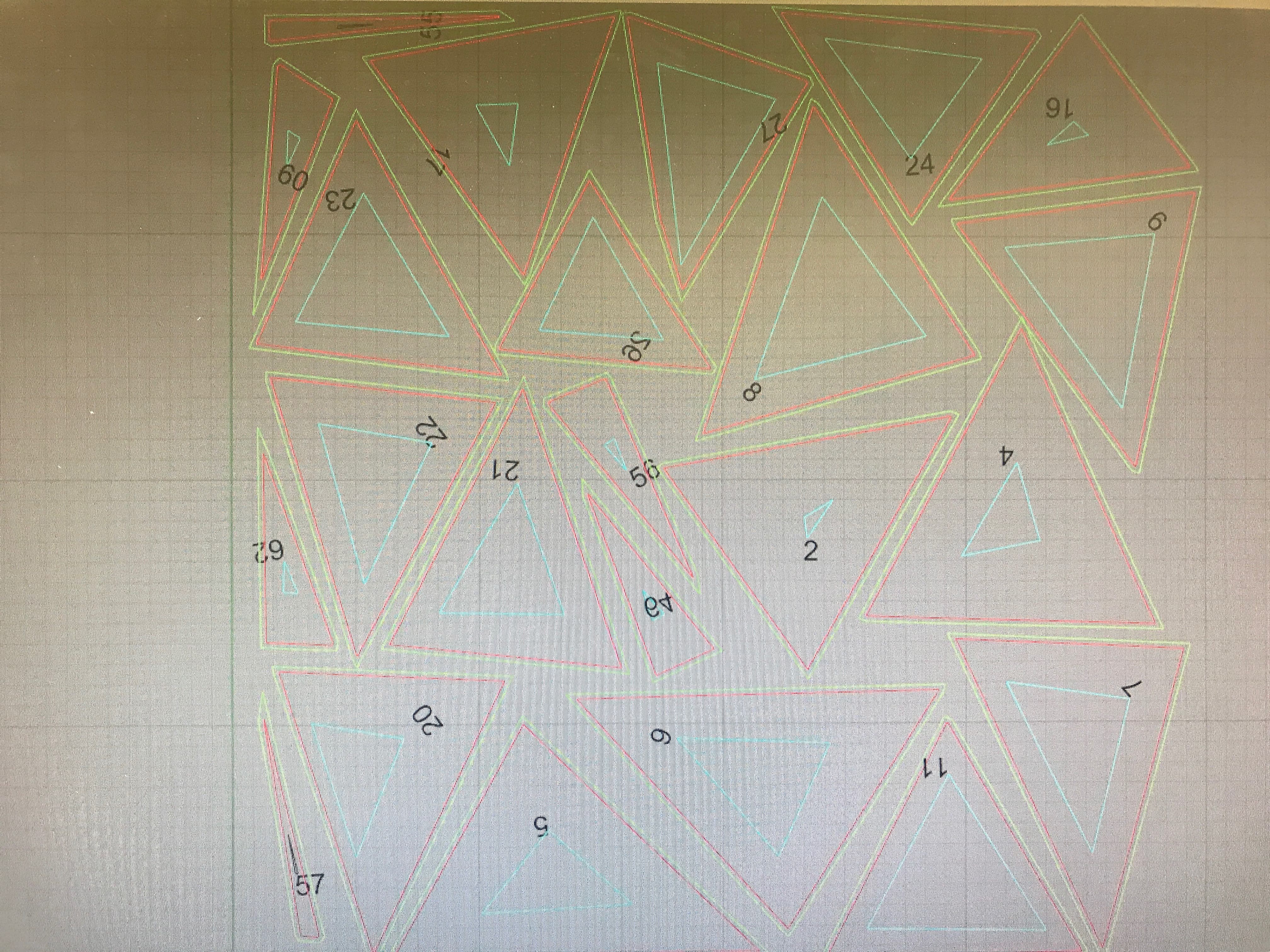
Figure 25. First I went through and labelled each piece, the one advantage to them still being intact
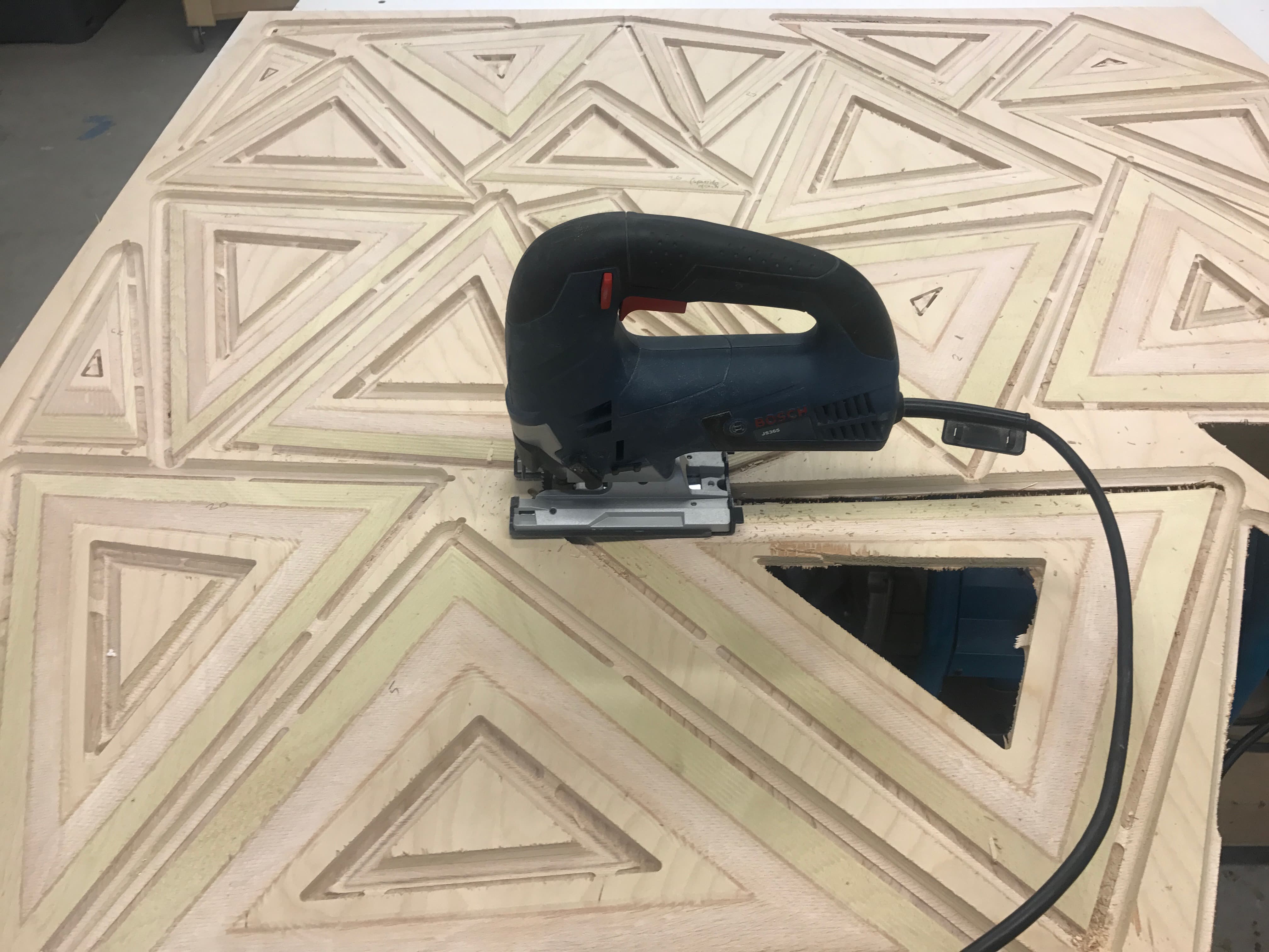
Figure 26. I had to go in with a jig-saw to remove each piece
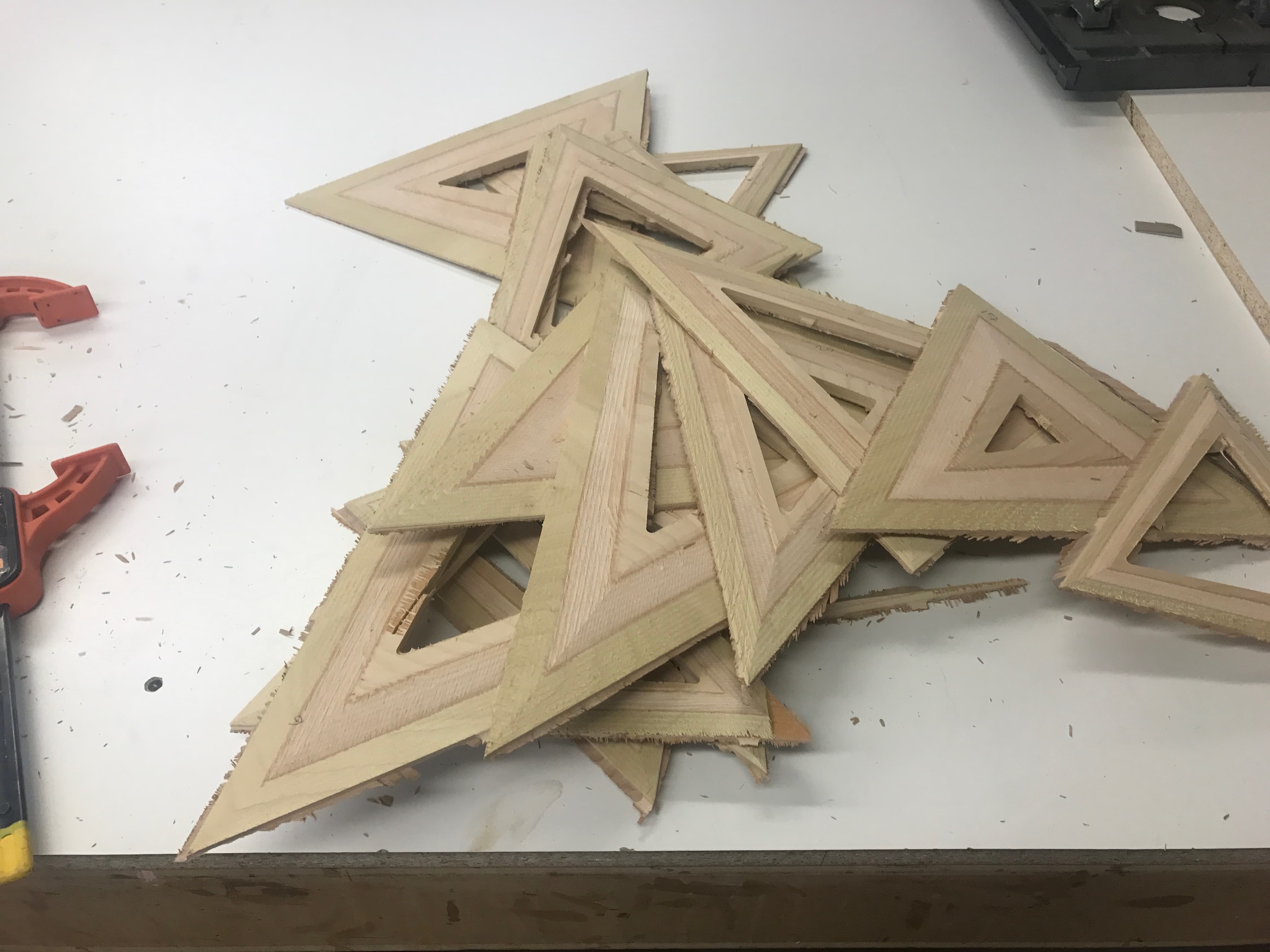
Figure 27. Rough-edged pile
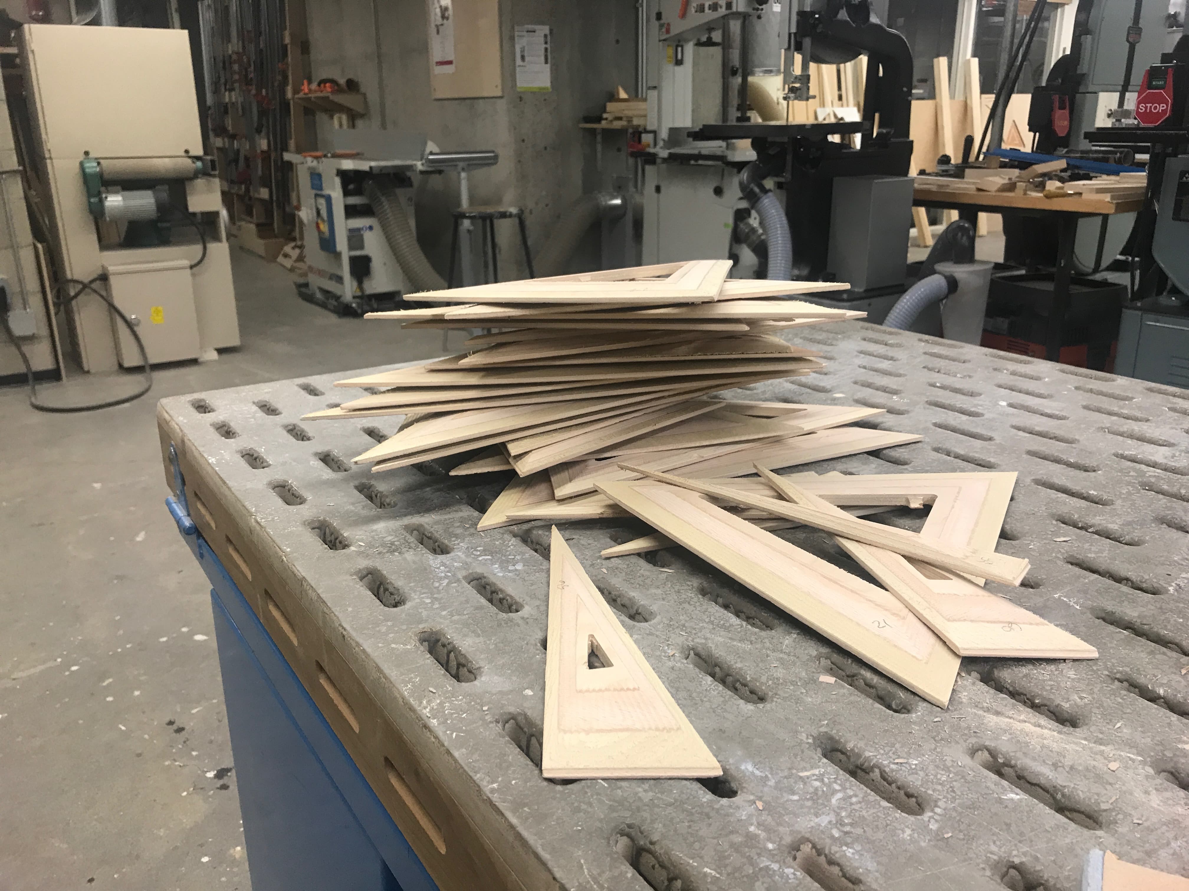
Figure 28. Sanded-outer-edged pile
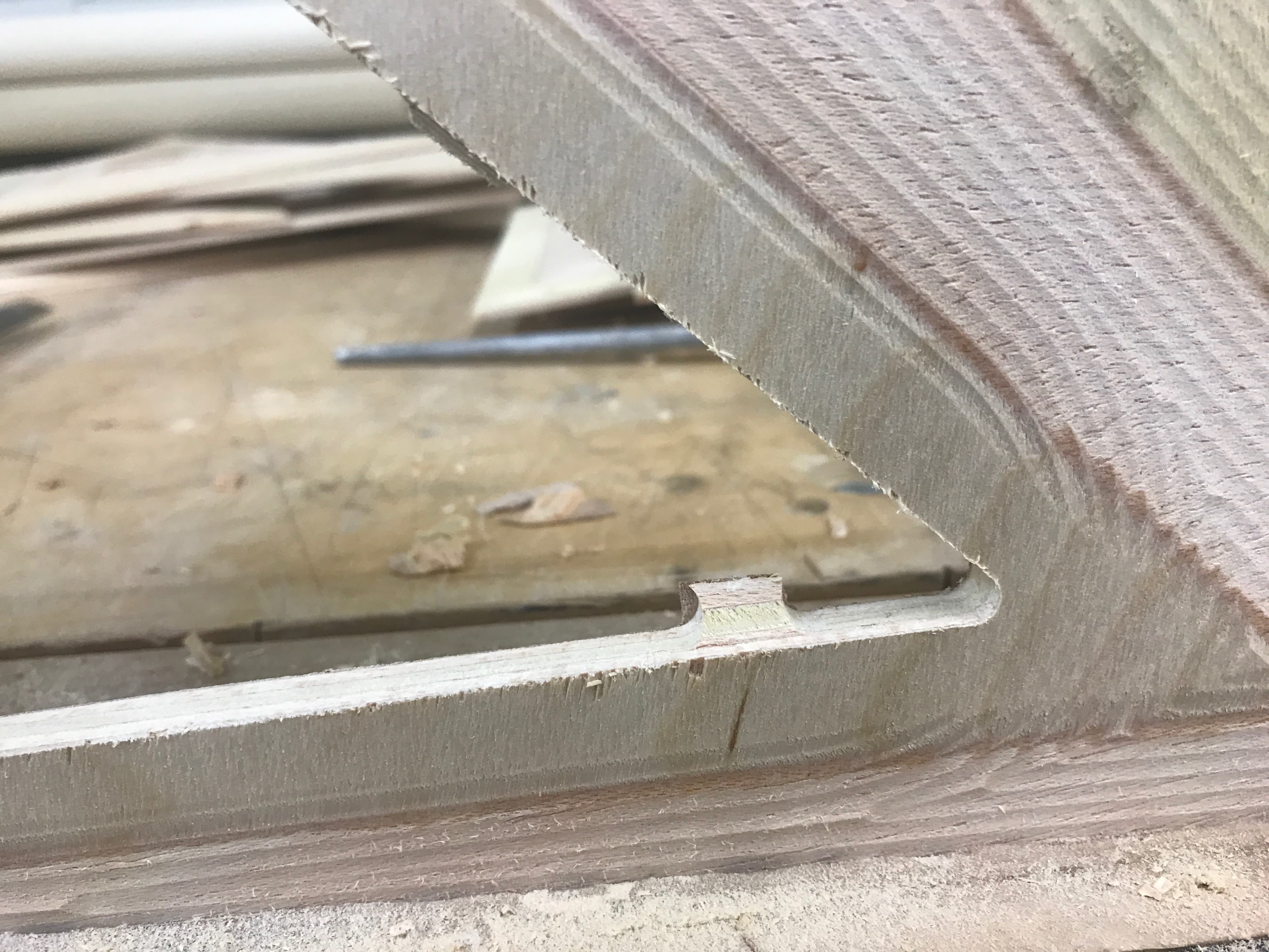
Figure 29. Close-up of Tab mistake
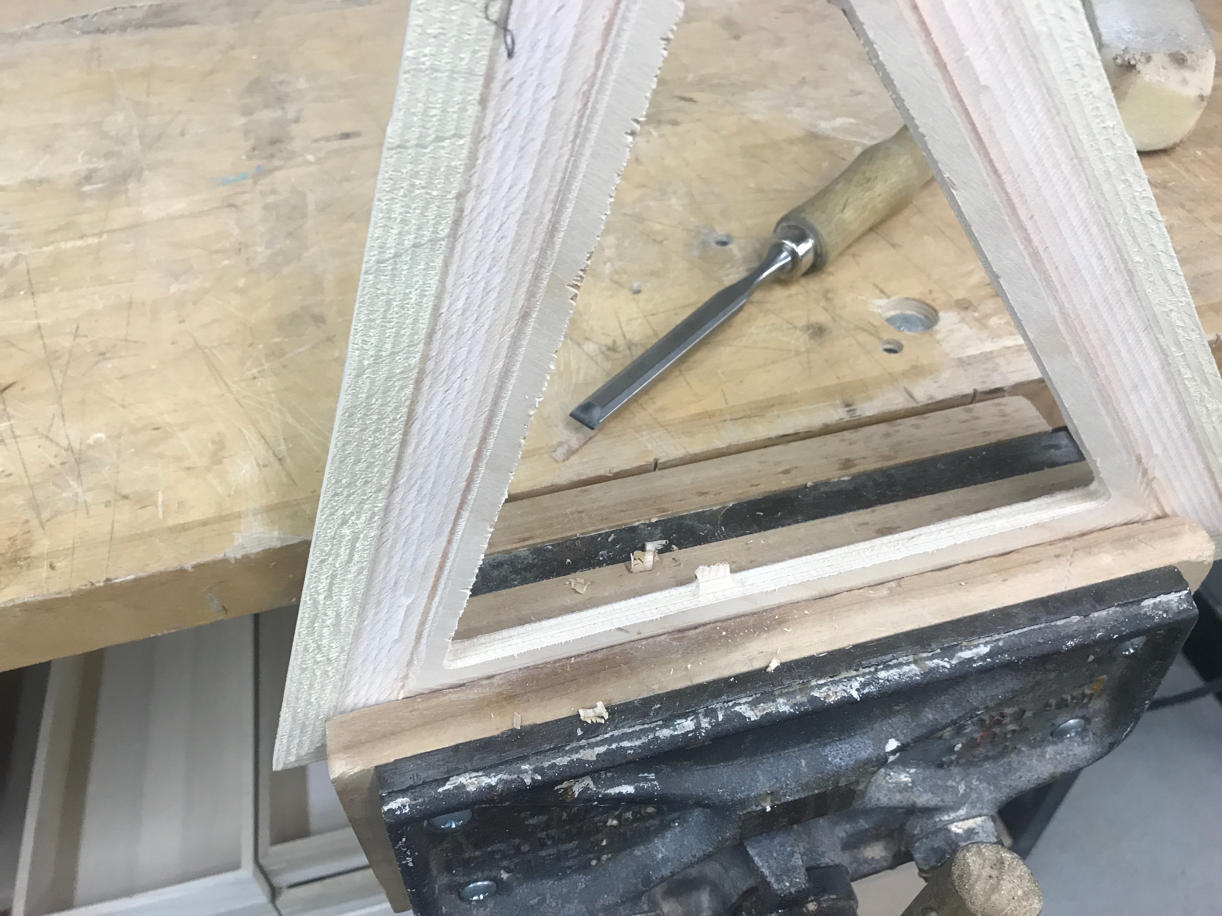
Figure 30. Chiseling off tabs
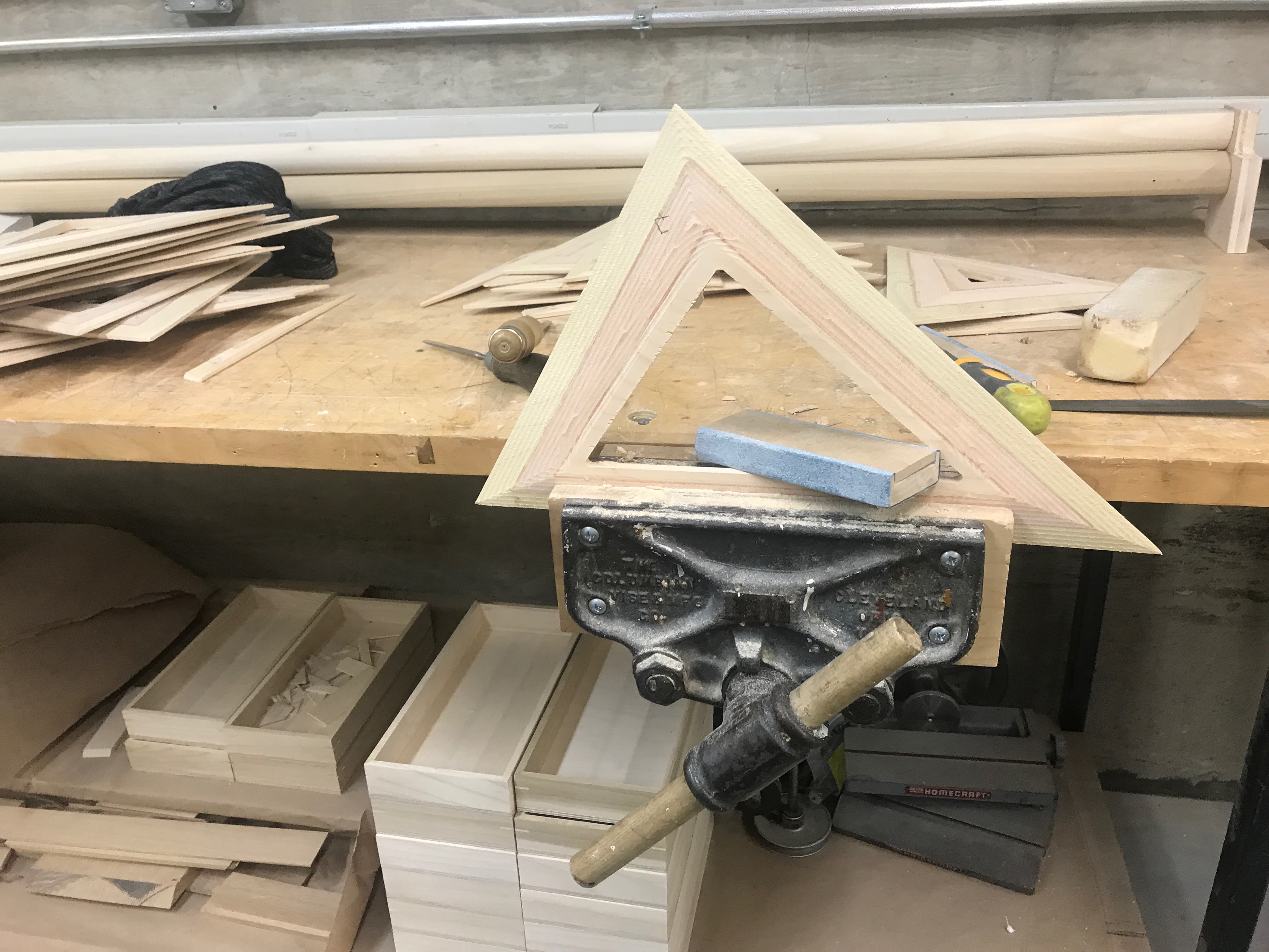
Figure 31. Smoothing inner edge
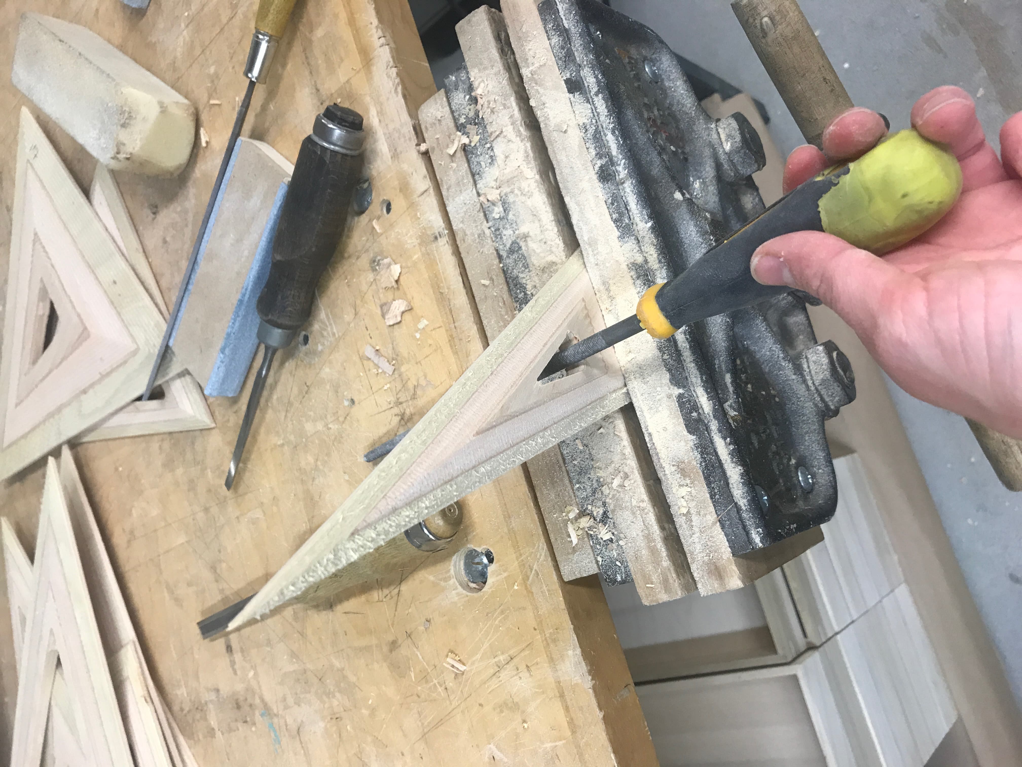
Figure 32. Filing fine inner corners
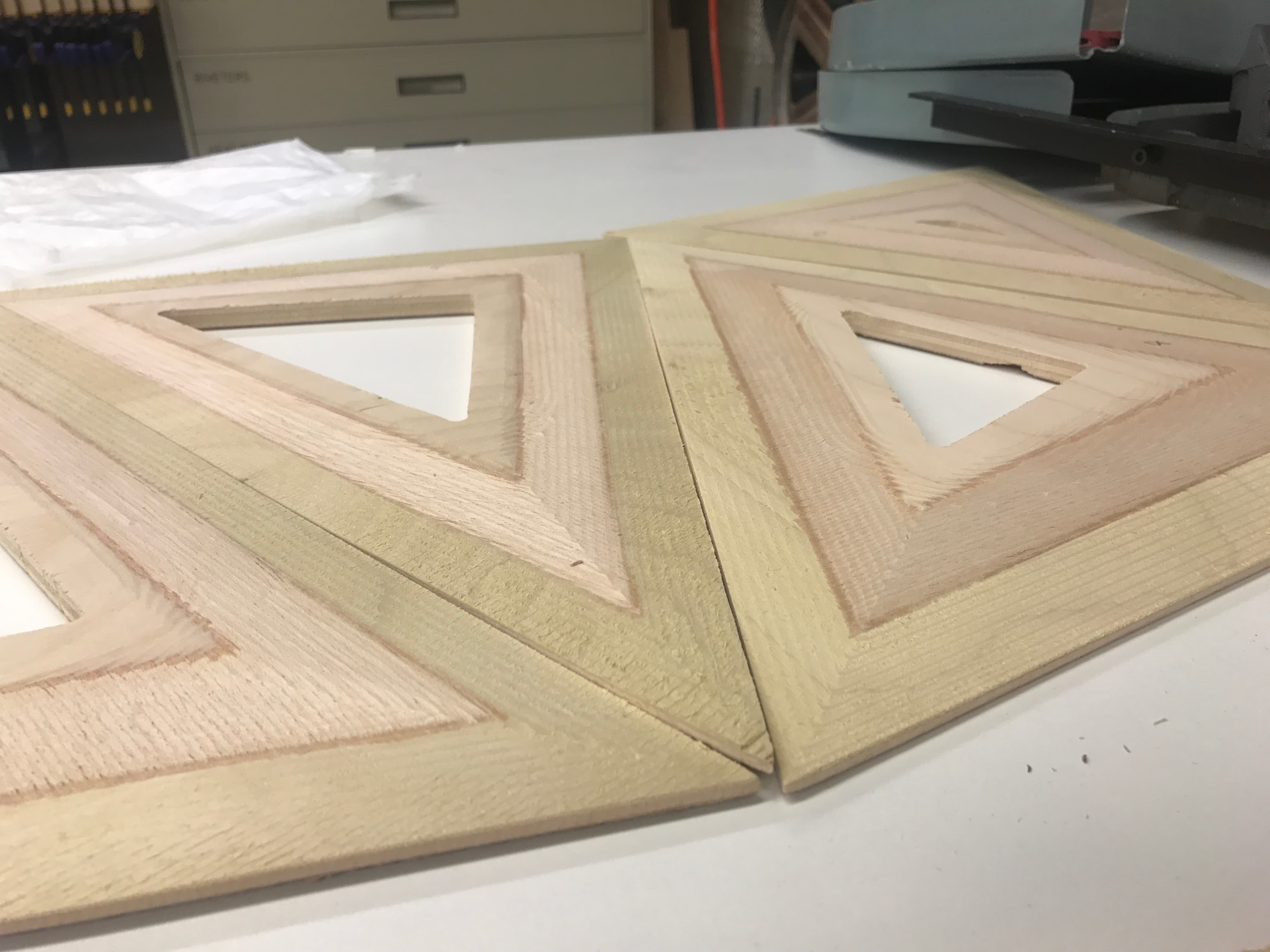
Figure 33. Close up assembly
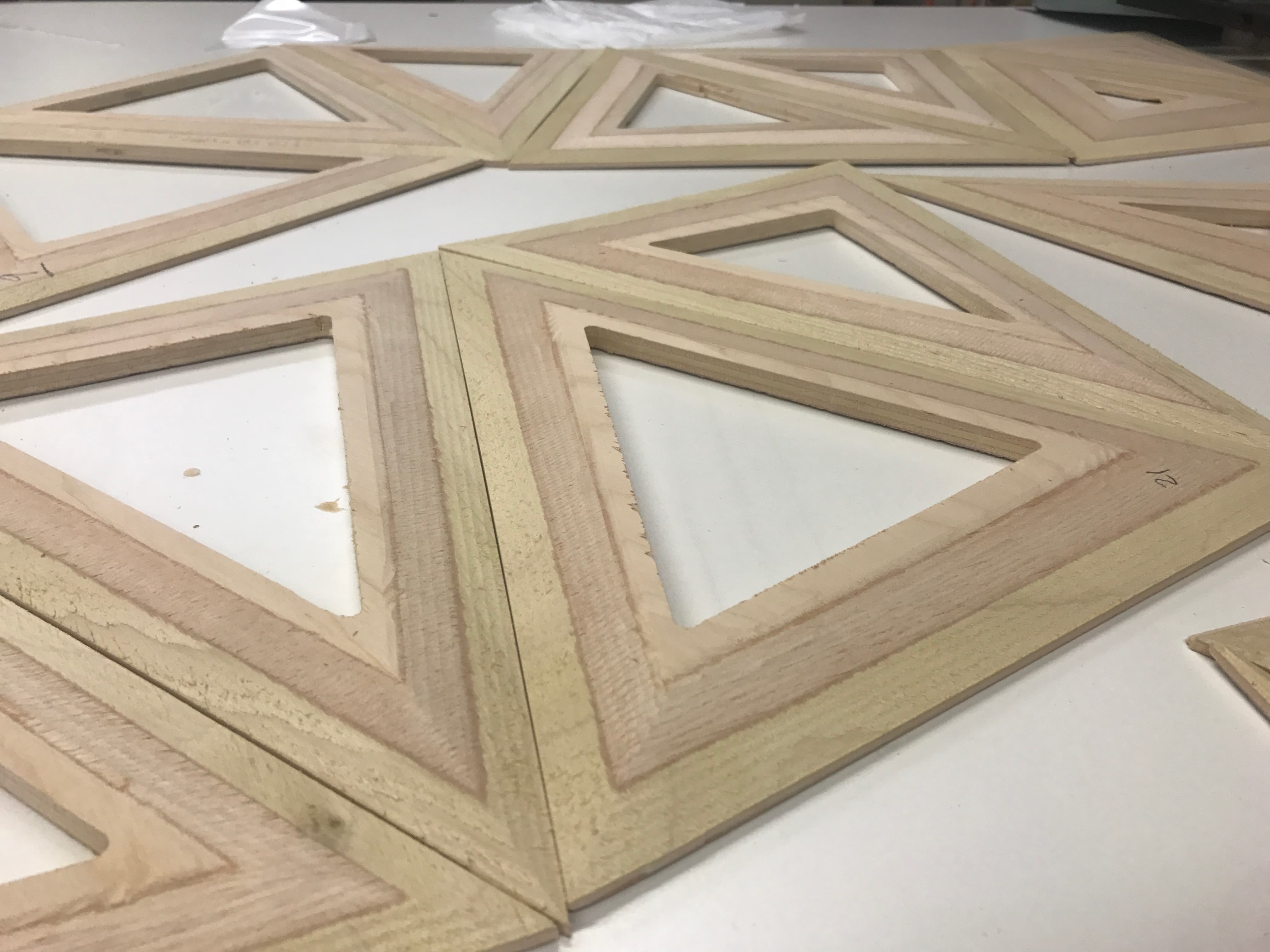
Figure 34. Assembling
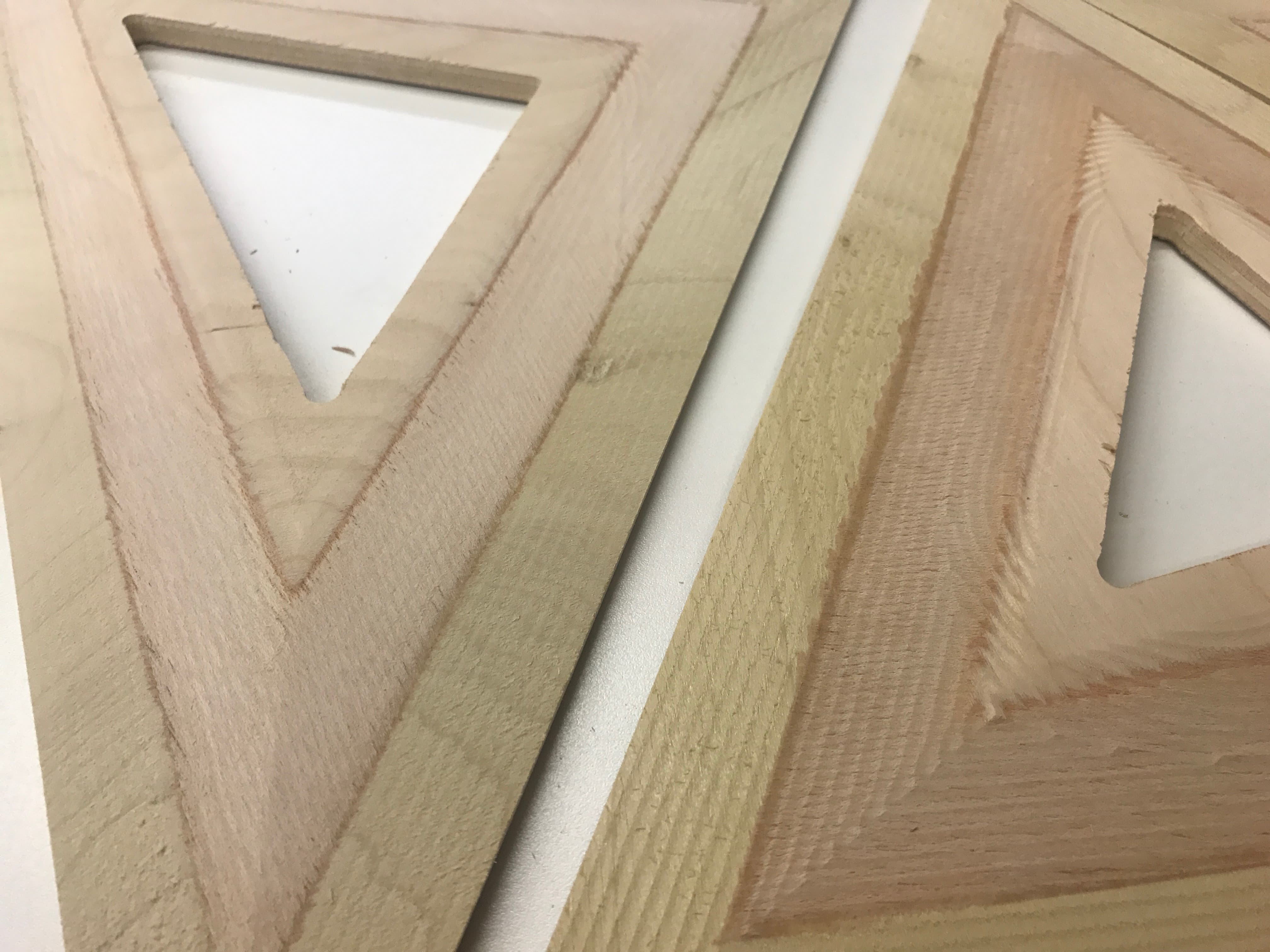
Figure 36. Sanded face vs. "raw" face
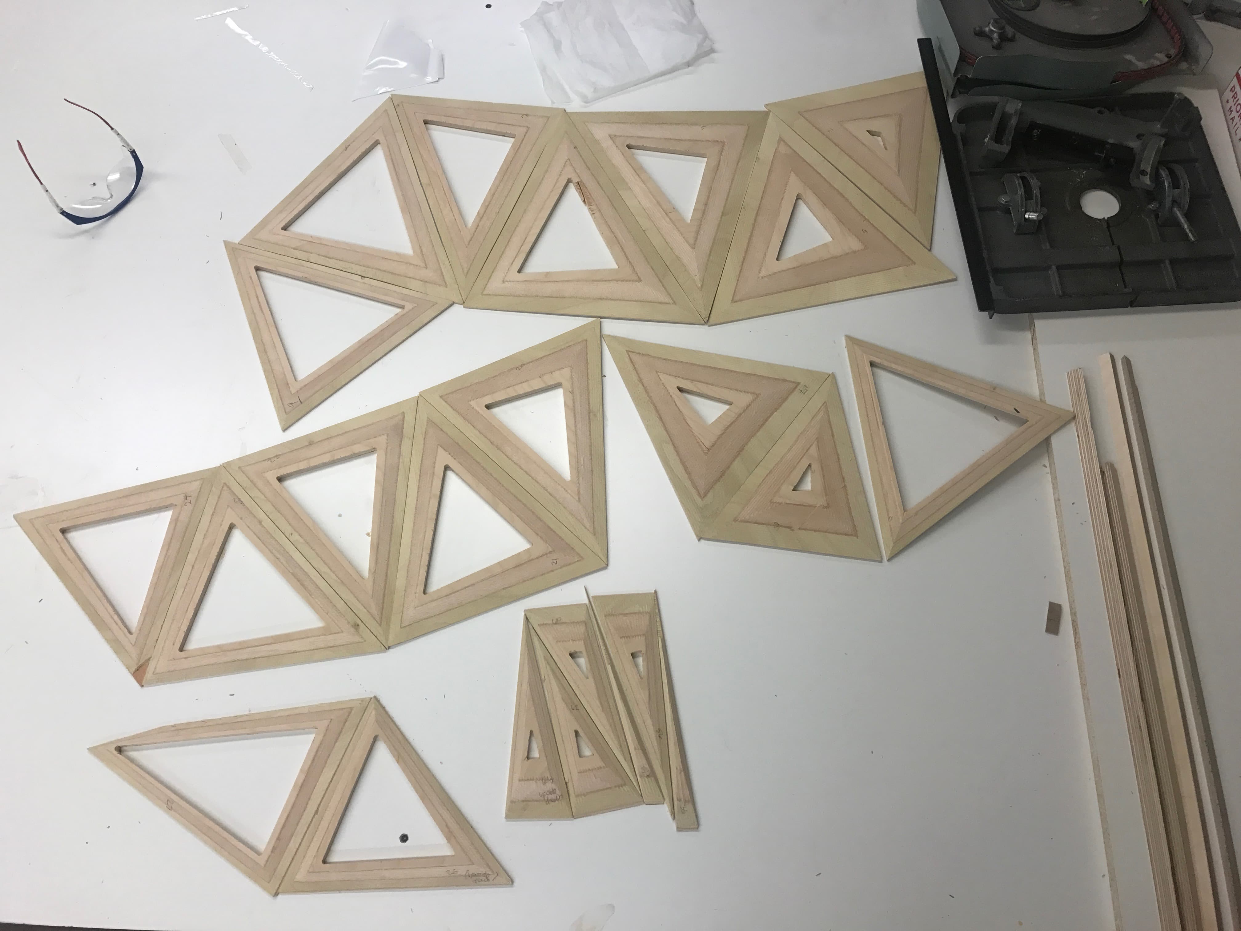
Figure 37. Full assembly thus far
Ultimately I will need to get more wood to finish up the piece. I will get a higher quality to avoid the de-lamination, the TAs recommended looking for a grade Boulter Plywoods calls "void free" Baltic Birch. I also think it would look much nicer with a finer laminatio to get a denser striation, and possibly a bit thicker of a material to have a more dramatic slope. I think this was a great first attempt and I look forward to finishing the installation!