Kim
0
1
10
11
100
0101
0110
0111
1000
1001
1010
1011
1100
1101
1110
1111
final
My final project is bringing Pixar Anglepoise lamp to the world!

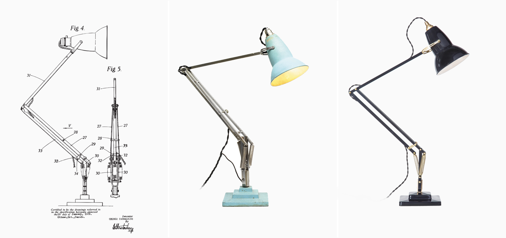
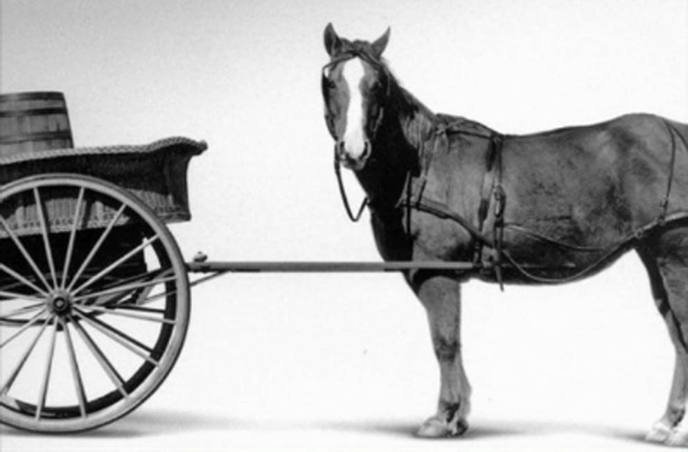
Anglepoise is one of the most iconic industrial designs, and this tiny human arm-looking device changed the desk to the workstation. The anglepoise table lamp was invented by a car designer named George Carwardine (1887–1947). While developing new concepts for vehicle suspensions, he created a mechanism that he recognized had applications in task lamp. The arm of the Anglepoise can move in various directions that users can adapt to their needs.
For the final project, I want to make Anglepoise alive. My goal is to make a lighting device that tracks the shadow and reshape or reposition itself to cast the light. I don't have to worry about my head casting a shadow on the book with this table light.
The first thing I have to explore and study for my final project is what mechnical mechanism I will use for the lamp arm. I once made a light tracking device with arm structure that can shape itself and orient toward the light source. For the Shadow-Buster, I will continue design how can lamp arm move smooth and accurately
What Anglepoise fascinated me is its elegantly balanced arm structure. George Carwardine mentioned that the lamp has constant tension in the system. I also want to make a mechanical system with a simple mechanism that plays with gravity and tension force.
The original Anglepoise lamp inspired the first test for the moving arm mechanism. However, I made the top part dependant on the bottom part of the arm. Rotating the disk on the bottom causes the arm to shrink and change the height and direction of the lamp.
I like the simpleness of the structure, but it needs further development. It can be folded and lower its body, not simply folding the top part down.
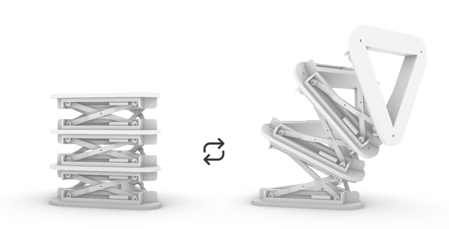
The second idea of the arm mechanism is that the triangle tentacle shapes itself to flash the light to the dark spot. This component is a spine-looking structure that operates when the spring gets compressed by pulling the wire. Wire can be pulled by servo motor.
I wanted to start making a mockup for the moving mechanic parts for the lamp arm.
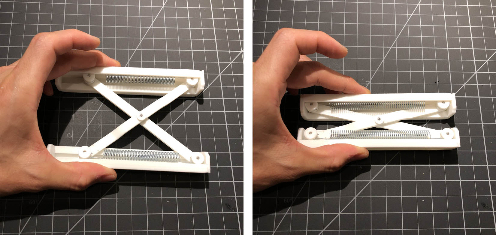
Okay, I don't know what I was thinking. I just made a spring, which does not give any movement for the lamp to orient itself. The joint has to move at least 2dimensionally to make the arm structure bend itself and flash a light at a different angle. The 'spring' I made only moves in one direction. Dumbest move you can imagine.
I found many problems with my design from this mockup. I didn't think about how I could make this arm move 3dimensionally. Even this spring can bend and incline toward both sides, and it does not make the triangle arm can move freely. I need to make this spring detached from the triangle plate to make each corner of the component can extract and contract.
Also, the wheel does not move smoother than I expected. Maybe it is because the 3D printed parts do not have a smooth surface. Even putting the surface quality aside, the force point is too far from the resistance point, so I need to redesign the part that can move three-dimensionally and more simply.
Even though I had to redesign the mechanism, I wanted to solve the dumb mistake I made. It is simple to give more freedom to the component by removing the pin between braces. Now, the component can stretch and be inclined in different directions.
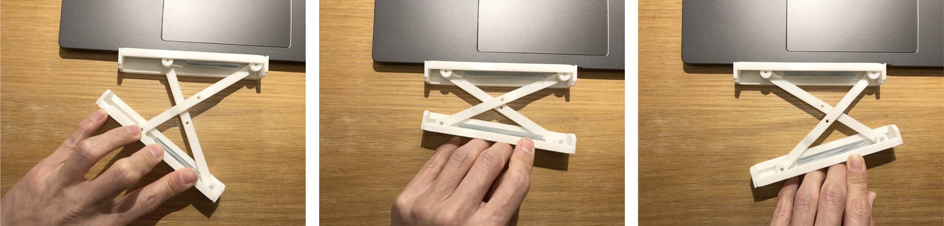
AWWW! The component can move like a serpentine! I will keep this for later use. I will explore the developed version of Arm test1 next time.
It is satisfying but doesnt work for the whole machine. I have to go back to work
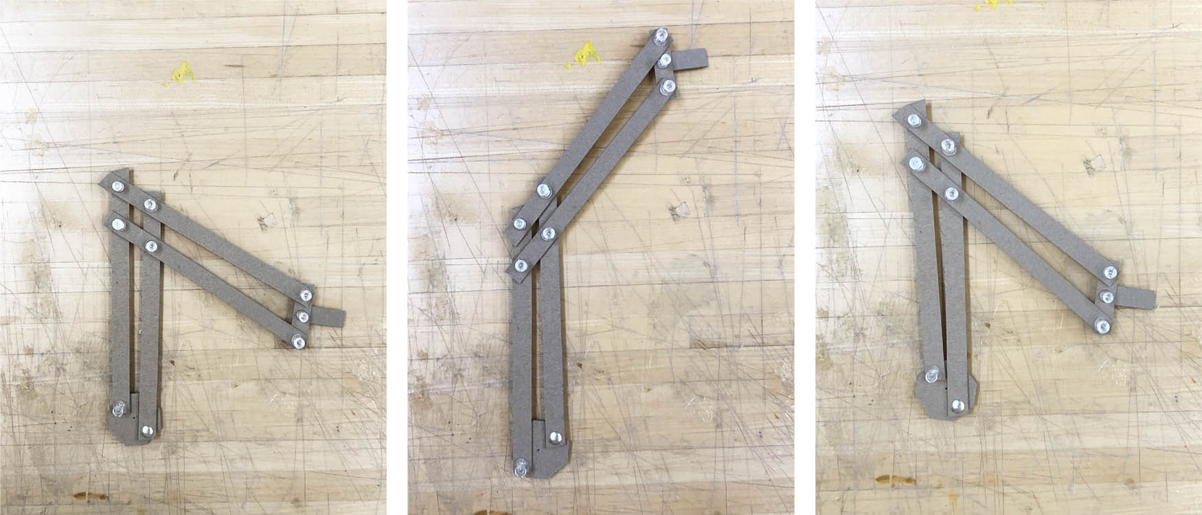
The beauty of Angelopoise is in its structural balance and tension. The object does not look heavy because you cannot read compression force in its structure. The heaviest part of the lamp stretched far forward, and the counterforce is the tension from the springs. I stepped back and saw Angelopoise again and decided to test arm mechanisms that contain the beauty of weightlessness and tension.
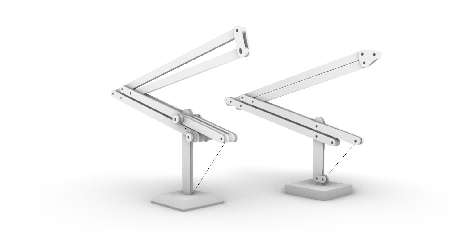
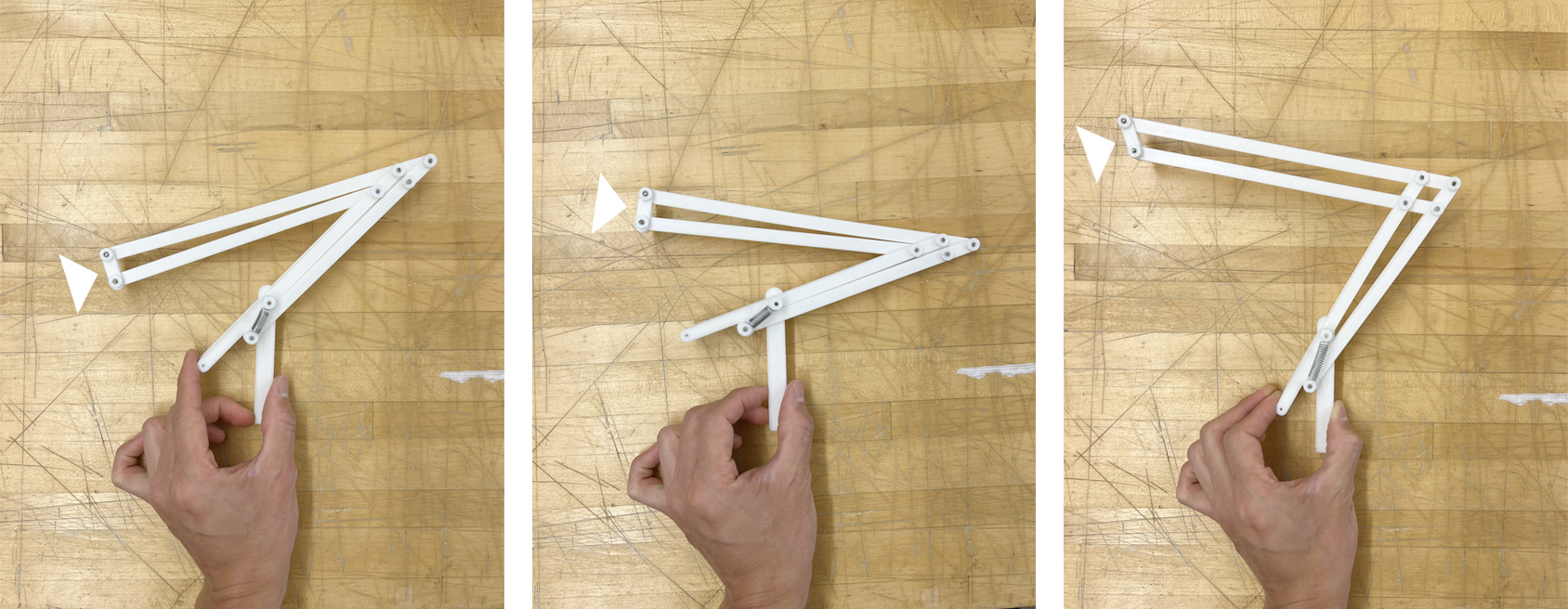
I made two similar prototypes to test which direction I have to provide tension to stabilize and move the arm when needed. Two designs have long stretched arms that lie back and stretch forward and up when the wire is pulled from the bottom. The key is to make the arm move smoothly to set up and control the motor force easily.
It is somewhat moving but not smooth enough. I'm not sure I have to change the moving mechanism entirely or improve connection detail to improve the movement.
As you can see in pictures above, the light source angle changes based on the arm height.
I found what's interesting in this study was this arm mechanism can have two different actions from one movement. By pulling the wire, it can change the height and angle of the light source at a time. Unlike the Angelopoise, which needed to make every part move separately, Connecting every part in the moving arm mechanism is important.
It's all about tension. People feel emotional tension from tension force. It is the same feeling when people are under a long-span cantilever or crossing a suspension bridge. The study model I made falls backward if it loses the tension from the wire. The structure that is balanced by a thin wire has an aesthetic of precariousness.
For the next step, I wish to test a design that allows the arm to stretch forward when it's stretching up and retract when it's lower its height. More detailed movement of the arm will allow Shadow Buster to reach the dark spot better.
I have been designing buildings for my entire career, but I am learning how difficult it is to design moving objects and machines. I might need to learn simulation tools for mechanical design. Playing with the grasshopper plugin Kangaroo is not efficient and intuitive enough to use as a design tool. What kind of software can I use? I need to ask around.
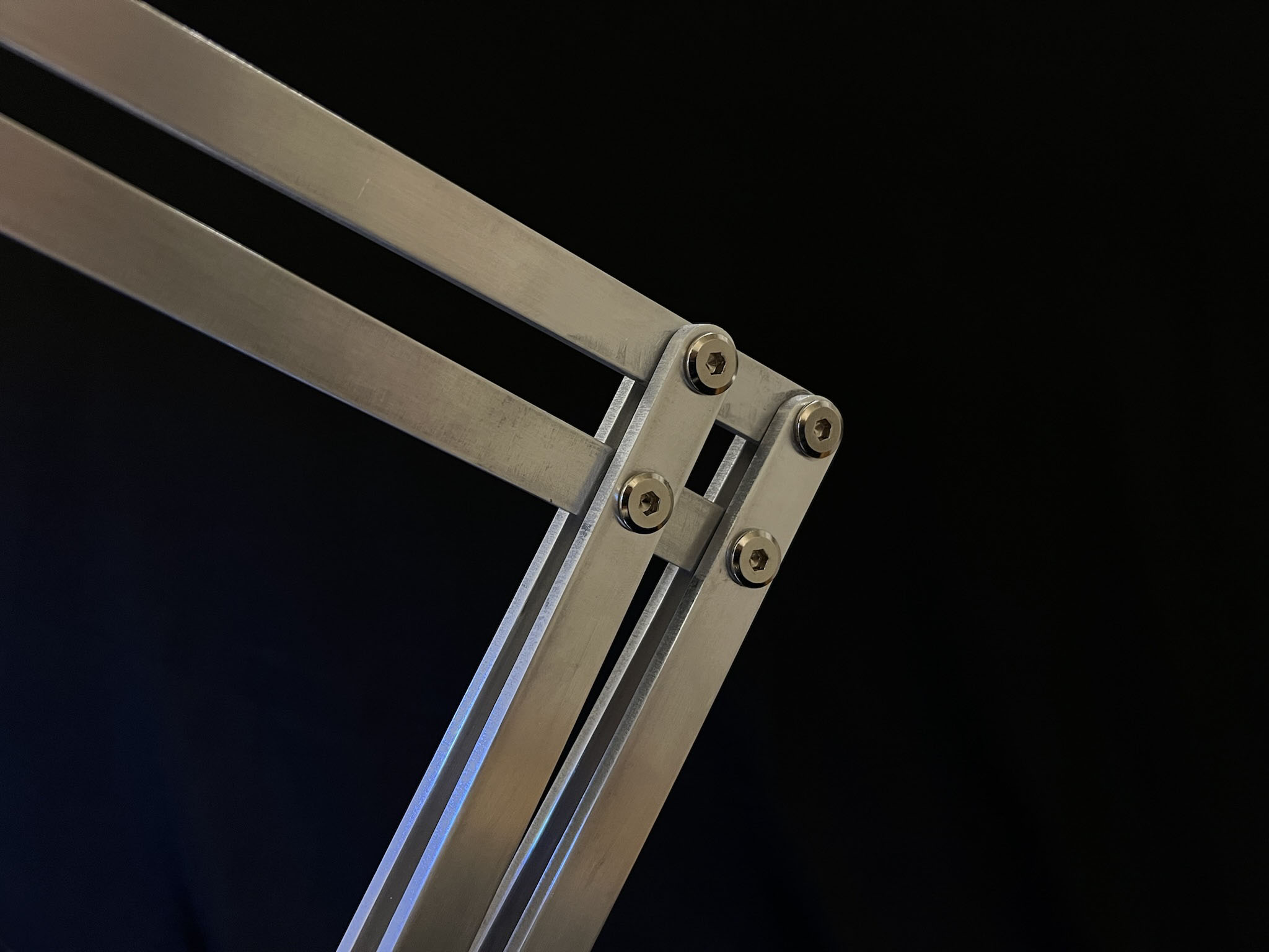
I found a proportion and arm mechanism that I like. Two servo or step motors are rotating and pilling wire to change lamp height and angle.
The wire connects the outer and inner arm by fixed pully, so the pulling takes less power and moves smoother than the previous version.
During the output device week, I was able to test the stepper motor pulling the wire of the scale model I made the previous week and see it's moving. It was as exciting as watching my first LED blinking!
I still have to figure out many things.
I've worked with a scale model but never made a full-size mockup, so I was afraid the motor was strong enough to move the lamp smoothly. Material choice was changed at the last minute from wood to Aluminum, which increased uncertainty of the final resuly.
Final video. Subtitle is "When dream meets reality"
I was very dissapointed that I realized the motor and machine parts were not designed careful enough to move the lamp smoothly.
However, I enjoyed the fabrication part and I learned how to use new machines such as Lathe and Waterjet.
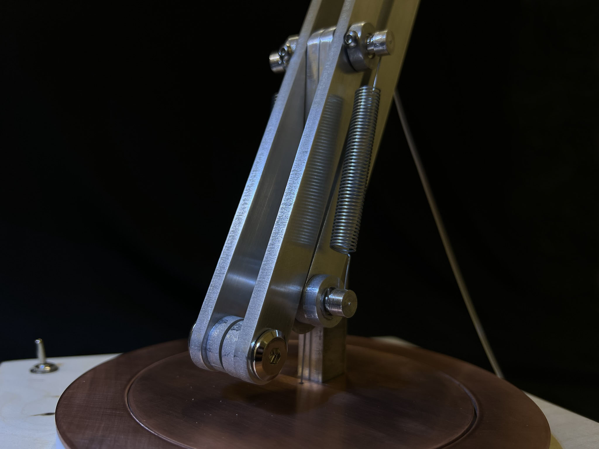
To make the entire arm is floated and sustained by tension, spring holding arms together.
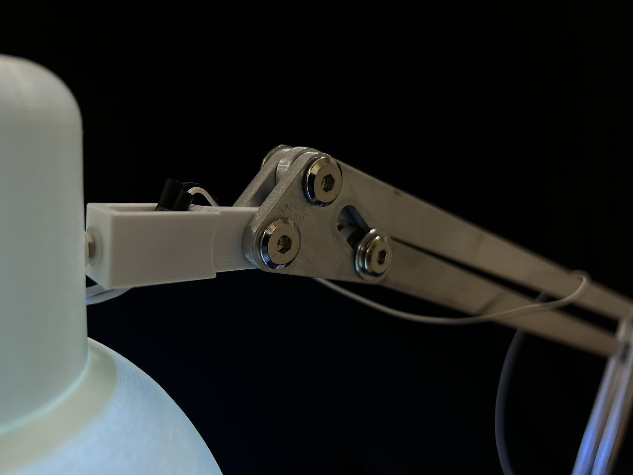
Machine joins are carefully adjusted to rotate and slide smoothly
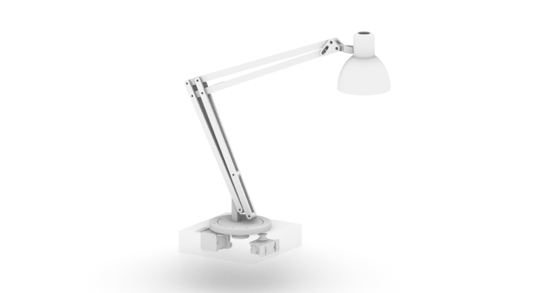
The entire machine was designed and tested in Rhino model and simulated in Grasshopper Kangaroo but actual weight and motor torque.
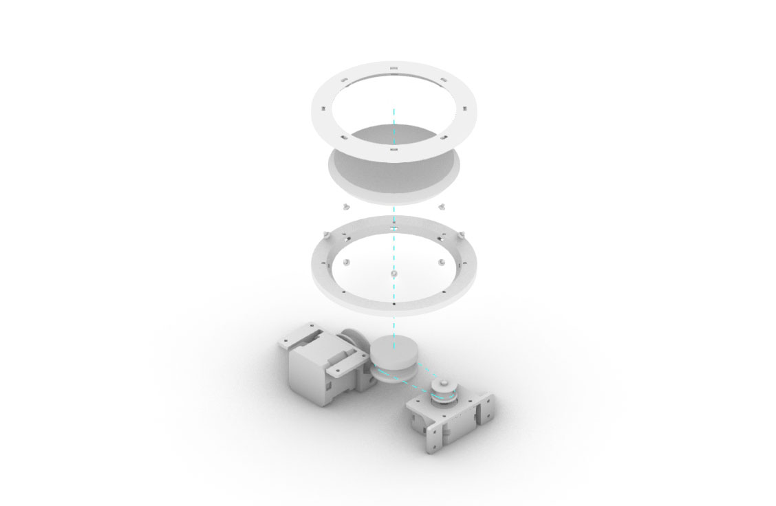
I 3D printed motor cages and made custom thrust bearing. The wire will be pulled by one motor, and the other motor rotates the disk on a thrust bearing.
I cut aluminum with a waterjet. The hose under the garment tank was clogged several times because the material was too close to the nozzle. Water can flow to the garment hose if the cut nozzle and material are too tight.
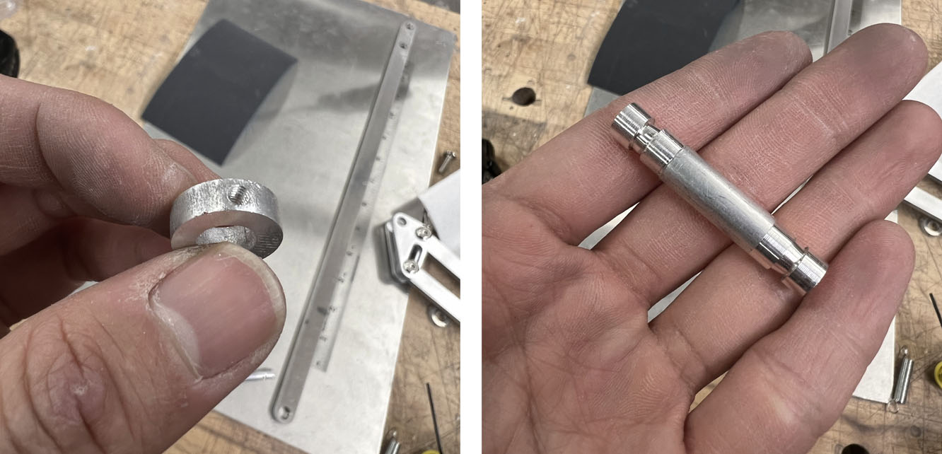
The lathe was practical to make an aluminum axis with a groove for the spring.
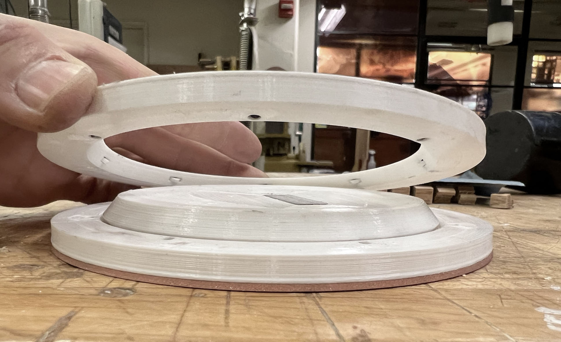
I made custom Thrust bearing with 3D printer and meral rod. Chamfered top and bottom piece supports the rotating disk.
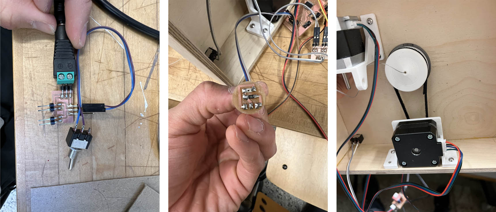
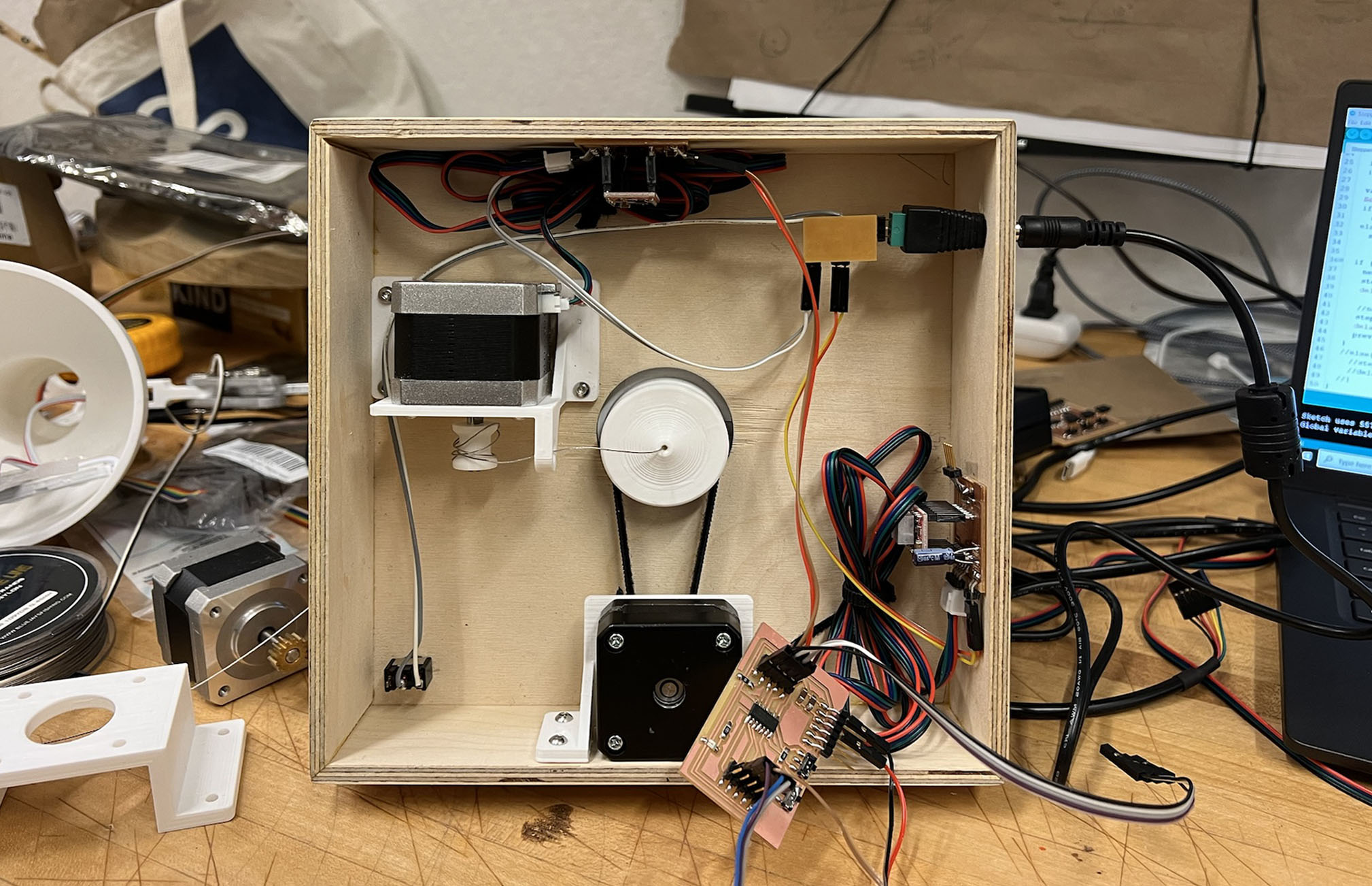
Interior of the base with all PCBs and wires. Two stepper motors, 2 phototransistor, 2 motorcontroller, ATtiny1614 microcontroller board, 12V power supply
I designed a device that senses the lighter and darker sides and orients the lamp heat to the shadier spot. The lamp head moves up and down to control brightness.
- What materials and components were used?
I used Aluminum for the main body, Brass for the rotation disk, 3D printed PLA for the thrust bearing, velcro for a band, plywood for the base.
- Where did they come from?
Most materials were from scrap pieces, where I got from N51 and Architecture shop.
- How much did they cost?
Stepper Motor: $7
12V power supply: $12
FTDI cable: $22
- What parts and systems were made?
4pin stretchable arm: Aluminum with bolt joint
Thrust bearing: 3D printed parts with metal rod
rotating disk with belt connection: velcro strip
- What processes were used?
1. Waterjet 5mm aluminum sheet
2. Carve 11/32in diameter aluminum rod with Lathe
3. 3D print and assemble Thrust bearing and motor cage
4. Make plywood base with Tablesaw.
5. Mill PCB with an SRM20 milling machine
6. Solder and program circuit boards
7. Assemble and wire connections
- What questions were answered?
How to fabricate machine parts with a metal material. (I used Aluminum for this project)
What mechanical system and connection to use for forced the machine needs.
- What worked? What didn't?
Machine parts moved but not smooth enough. I need to apply different mechanical connections to move pieces smoothly with limited stepper motor power.
- How was it evaluated?
It was a total failure to compare with what I imagined and planned. But the basic principles are working, and I learned how to make it better next time.
- What are the implications?
This device can be developed with a more complicated arm structure to have more diverse movement without placing motors on joints.
SRM20 PCB milling machine
Table saw
Creality PLA 3D printer
OMAX water jet cutter
Lathe
Mods
Rhino+Grasshopper
Arduino IDE
PCB
INO
Some more?