Kim
0
1
10
11
100
0101
0110
0111
1000
1001
1010
1011
1100
1101
1110
1111
final
First of all, I want to thank all TAs who worked so hard for a long time to teach me and bear with my vacuity and inexperience on electronic design. Shout out to Laura, Anthony, Calvin, Zach, and other cohort and staff.
It was the most challenging week so far. One, because I don't have knowledge and background in electronics. Two, it was so difficult to find out what I did wrong, from the board design to soldering and programming phases. This week is about the note of many failures and questions.
I started this week by learning KiCad and how to design a board and draw in SVG or PNG format to mill PCB. Zach's recitation was a perfect guide to follow step by step.
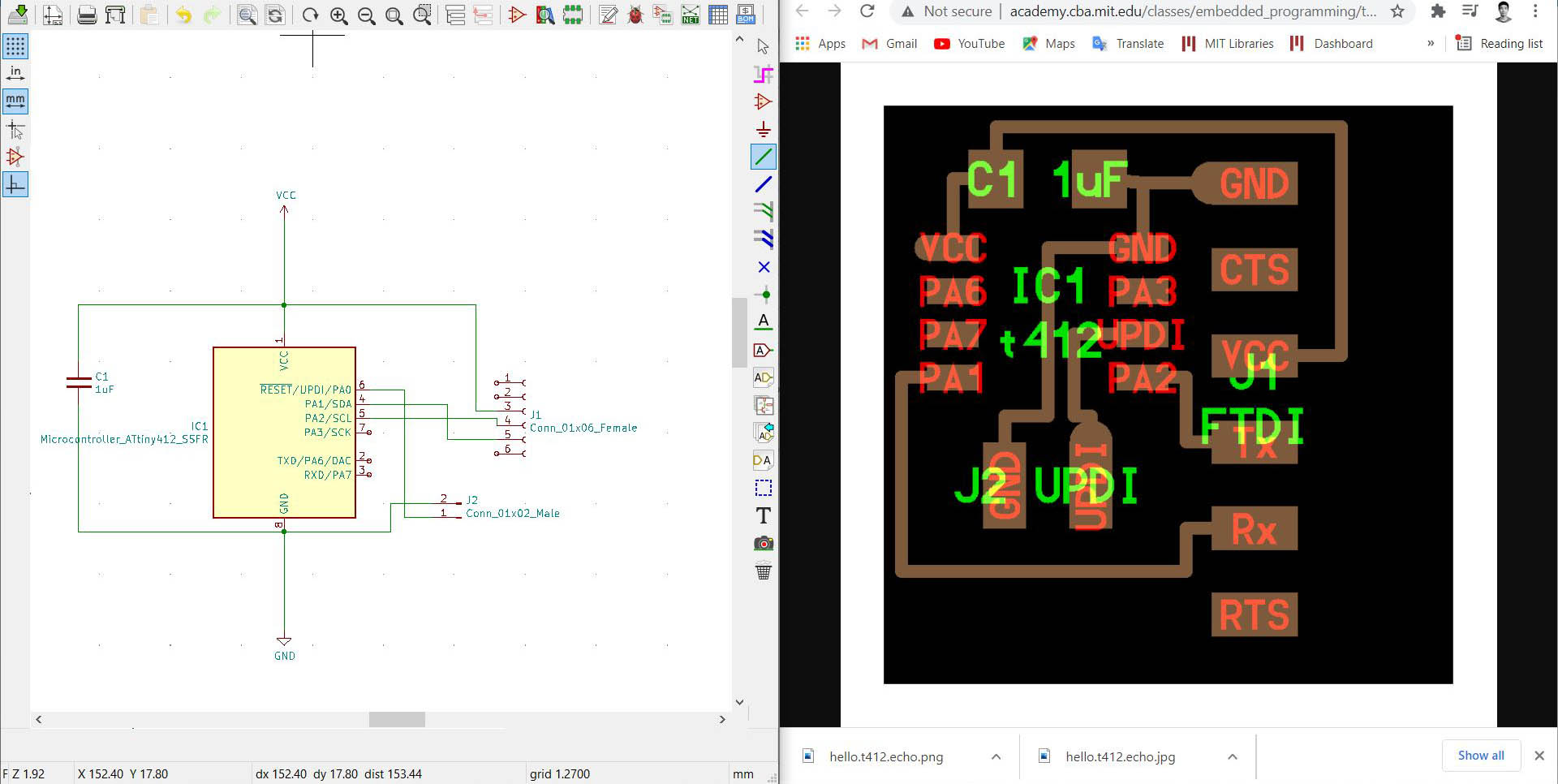
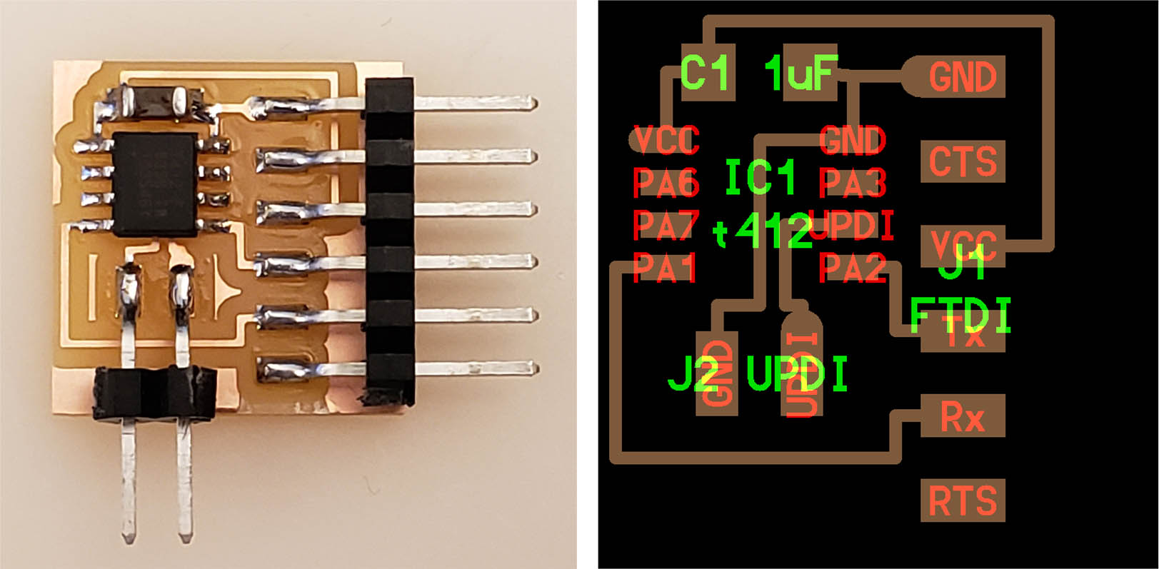
After setting up the KiCad library, The first practice was drawing the reference ATtiny412 Echo board from Neil's design from the HTMAA website.
It was straight tracing the existing board, but I learned a lot about the program and got more comfortable using it. One tricky part was post-processing exported SVG files.
I tried to bring SVG to the Adobe Indesign and edit, but apparently, the scale changed while exporting from Illustrator. I ended up using Inkscape and Photoshop and export into PNG. SVG is a vector file, so it might be easier to post-process the board design or bring it to another CAD software to edit, but it has too many different types of SVG, such as compressed SVG from Illustrator or Inkscape SVG, which Mods cannot read.
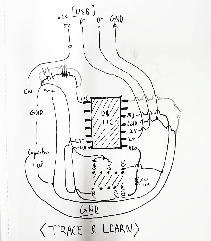
Before designing my board, I sketched Neil's D11C Blink board and put LED and button on top of it because I was not confident about what I learned in the class and searched. I connected one of the D11C pinouts to the LED and Resistor, another pinout with a button.
I tried to bring SVG to the Adobe Indesign and edit, but apparently, the scale changed while exporting from Illustrator. I ended up using Inkscape and Photoshop and export into PNG. SVG is a vector file, so it might be easier to post-process the board design or bring it to another CAD software to edit, but it has too many different types of SVG, such as compressed SVG from Illustrator or Inkscape SVG, which Mods cannot read.
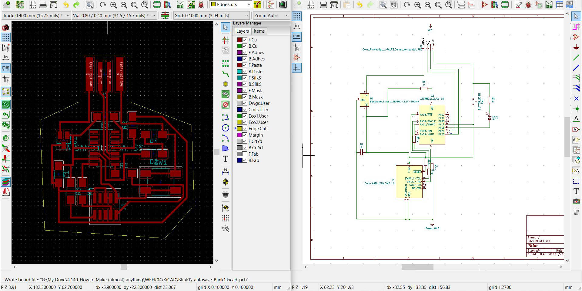
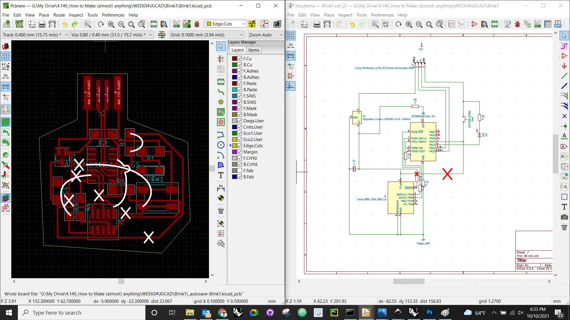
Image above: Not working
The picture above is the wrong schematic design and layout, and I made couple mistakes.
1. In the layout, the board is not grounded. I made a schematic with two grounded features, and I did not connect GND from D11C pinout to the USD GND. (I will explain more detail later)
2. one connection mistake between microcontroller and 10pin connector
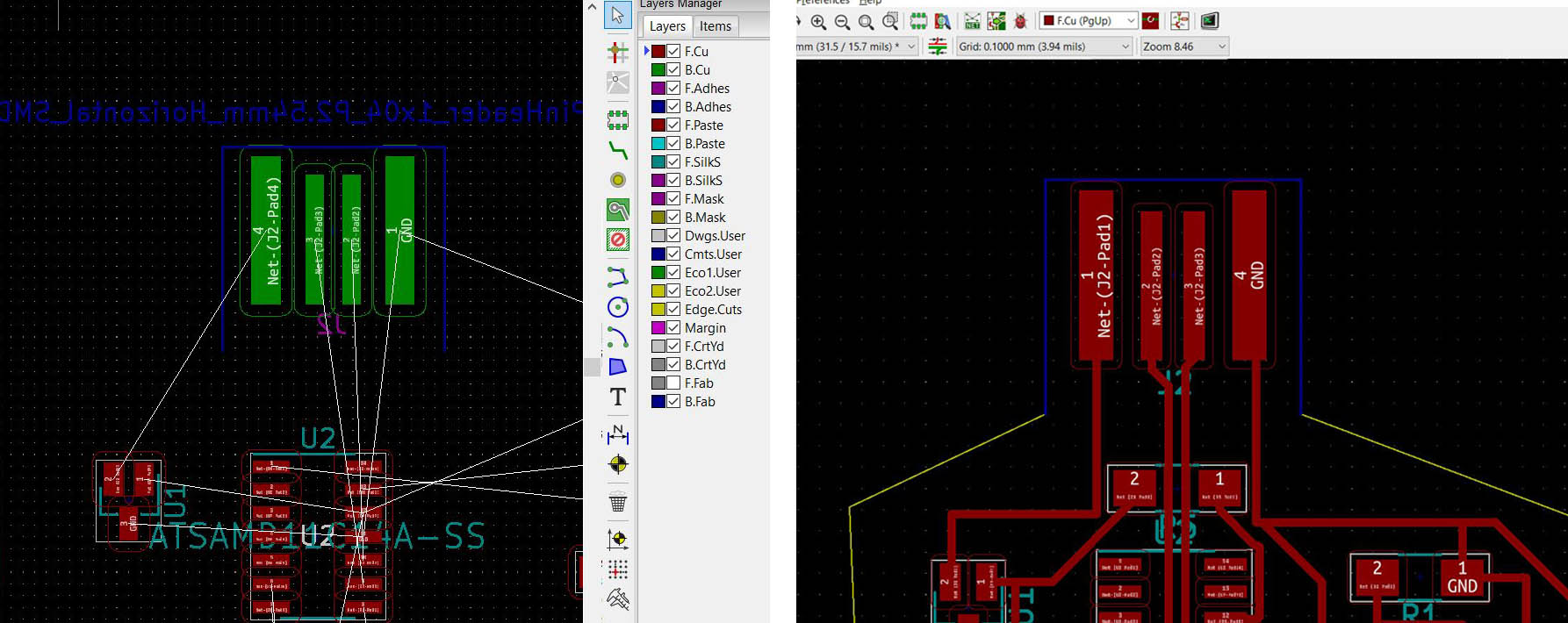
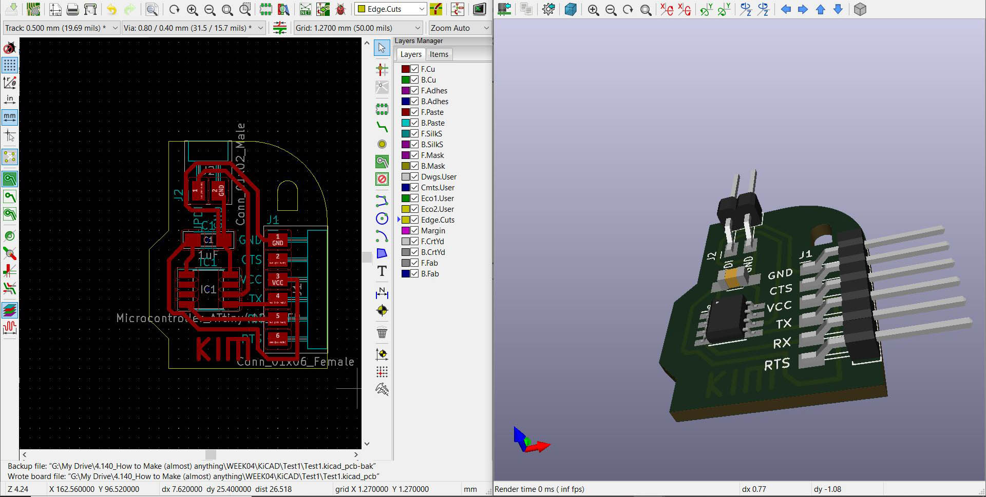
When I was drawing a layout, I had a problem flipping the USD, and I found you have to flip in the schematic to keep the mill on the same side. Flipping components in the PCB Layout design section means you are milling on the backside of the PCB.
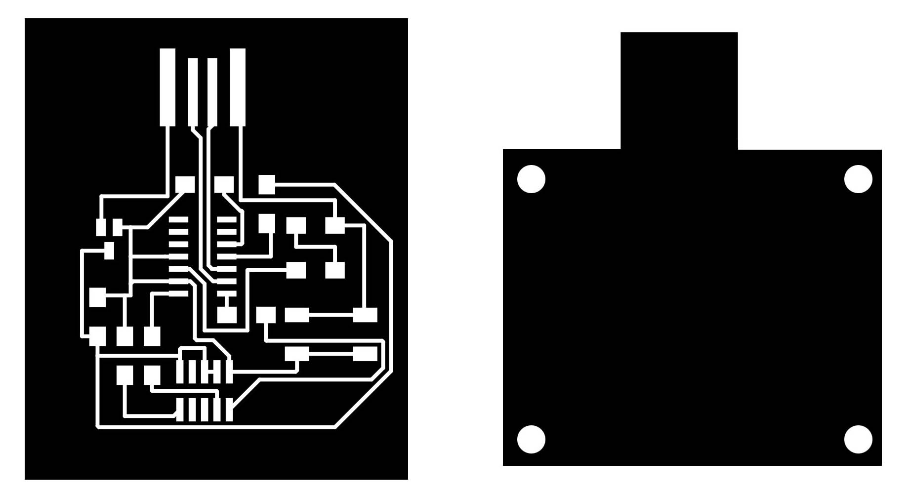
Image above: Not working
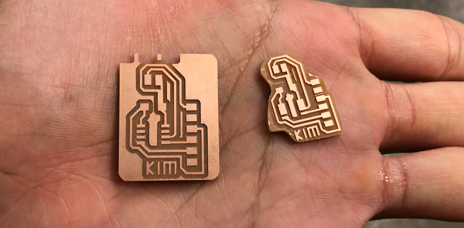
As I explained earlier, I had a scale issue using SVG in Adobe Illustrator, so I started exporting mill and cut layout in PNG. I used 500dpi. I tried to use higher dpi, but Mods were not reading too high-resolution files.
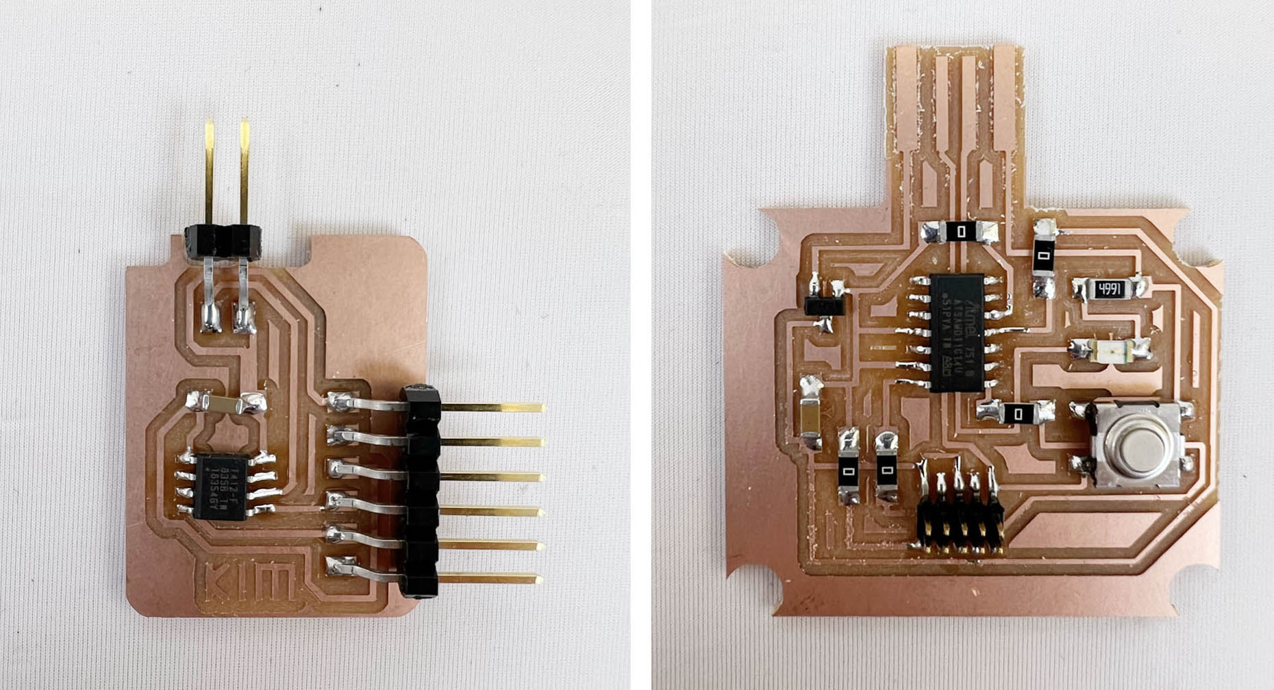
One on the left is AtTinny412 echo board, designed by Neil, and the right one is D11C LED and Button board. I will explain later on the programming section, but both got bootloaded even though my D11C board was designed wrong.
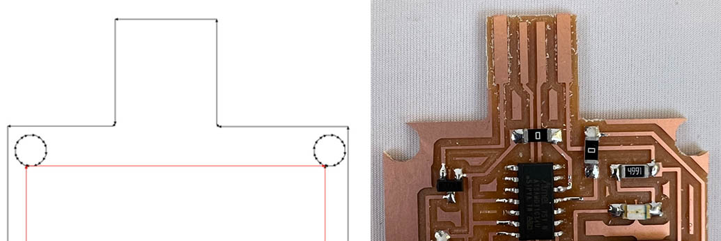
I also learned that the line represented in Mods cut path is the center of the milling bits. Therefore, I lost the corner by making too little margin between holes and edges.
It is not easy to tell from this video, but there is a weird thing on this board. I designed to make 'High' when a button is pressed and 'Low' when the button is not pressed. However, when I gave power to the board, it lit up the LED, and it turned off when I pressed the button.
It would be better to talk to TA after I made a schematic, but I was confident enough to make a board without checking, and it was a huge mistake.
After talking to Anthony and Calvin about my board layout, I found that the button is working the other way because the board is not grounded, and the button connects the board grounded. (Thank you again Calvin and Anthony)
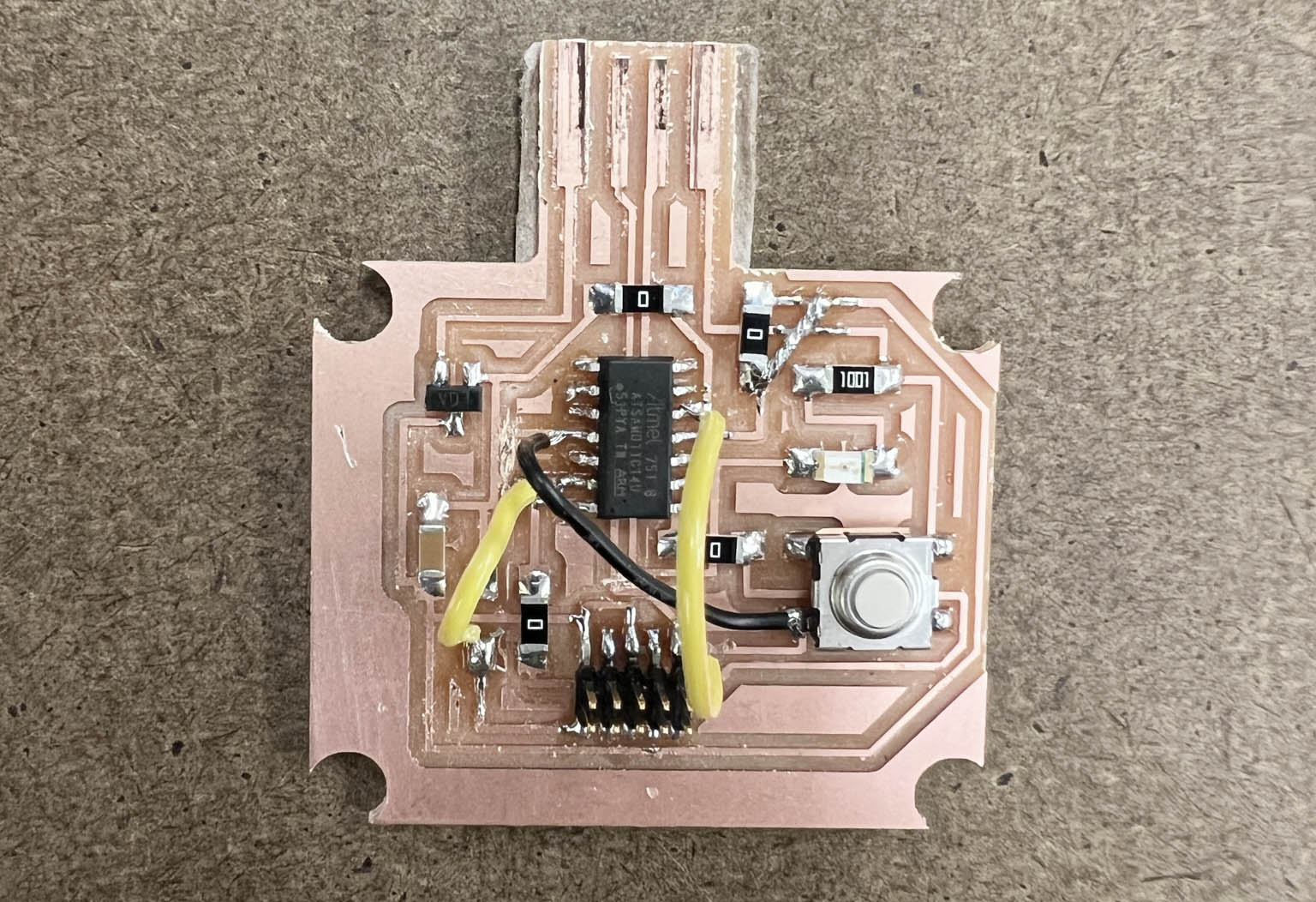
It was too late, and I wanted to move forward, so I decided to fix the board in a gangster way. I scratched the connection with the knife where it needs to be disconnected and wired the new links. It turned out a Frankenstein board, but now the board makes more sense.
I also changed the resister from 4.9k to 1k (very dumb that I calculated with 5v and current 1mA)
It is working now. Before I fixed the board, the Arduino ide did not read the port and giving me an error. Now the board can be programmed.
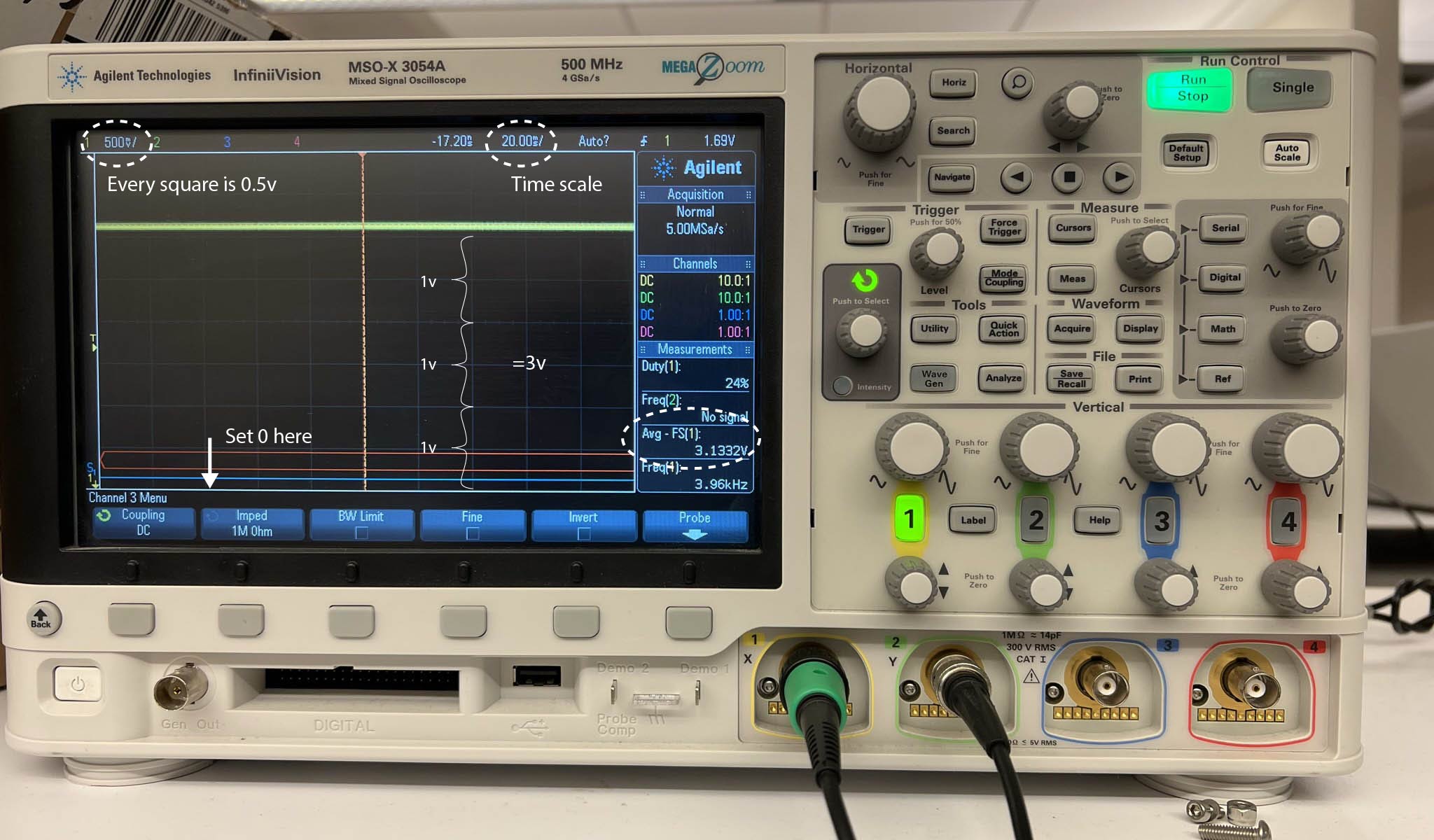
Anthony taught us how to use an oscilloscope. I tested my board with feeding a power, and touch the ground and line goes after Output from the regulator. We set up a voltage scale to present 0.5V per square, as you can see on the screen. The voltage on the board is flowing 3.13 on average, close to 3.3V, which is supposed to be.
Thanks to Laura and Calvin, I explained earlier that I get to bootload my AtTinny echo board and blinking board. I followed Laura's guide to set up EDBG, but I could not call edbg from my terminal with the edbg -h command. I will explain later how the problem was solved.

I was using the Arduino example code. Calvin helped me figure out why the board was programmed and working, but LED is not blinking. He guessed it was the wrong pinout match, and he was right!
Somehow, the pin number I had to put was PA number. I don't know what this means exactly, so I need to ask or search a little deeper
LED started working after set a correct PinMode for the LED. Remember, it's PA number.
The button is not working well still. I want to make one more from scratch and compare it with this Frankenstein board. Still a lot of things to catch up.
Electronic board making
- Roland SRM-20 (PCB milling)
- Soldering station
- ATATMEL-ICE
KiCad
Inkscape
Photoshop
Mods
Files