Kim
0
1
10
11
100
0101
0110
0111
1000
1001
1010
1011
1100
1101
1110
1111
final
This week was more about learning about using AVR microcontroller AT tiny than learning about input devices.
I've been sticking to ARM processor SAM D11C from the board design week. This week, I was planning to start by learning through making Neil's sample. However, I quickly realized that I didn't know how to program the AVR architecture microcontroller, and I had no idea how painful it would be to program and talkback without an FTDI cable.
I was working closely with Demircan Tas. I appreciate his genius ideas and patience that made us work through many problems.
This week, I wanted to make a board that detects the darker spot in the space. I thought this would be helpful for my final project, but I'm not sure this will work for a shadow-detecting table lamp.
The board works with two phototransistors on both edges of the board. The graphic I made from the grasshopper tells which direction is darker, and the stick is pointing toward the darker side.
I started by making Neil's AT tiny45 phototransistor board to understand input devices. My hands were moving before thinking, so I failed to program with USB using the IDE setup I sued for D11C.
Another issue was I was simply replaced AT tiny45 to 412 and re-routed GND and VCC, I needed to add 4.99k resistor. Also, RX and TX are going to UPDI, the board does not do anything.
After failing to program the first board, I started working with Demircan to program ATtiny412 through pins.
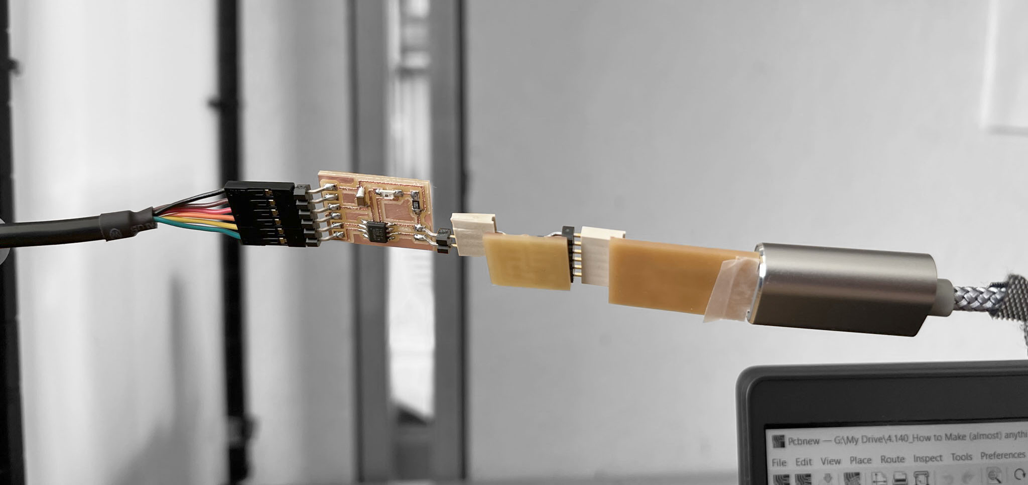
We could program through the D11C USB board, but the pin change through many boards, and connecting power input and programing pins to a long train of boards are unreliable connection.
Demircan brought up a genius idea to make a slide switch to connect UPDI and RX TX to microcontroller RXD and TXD pins.
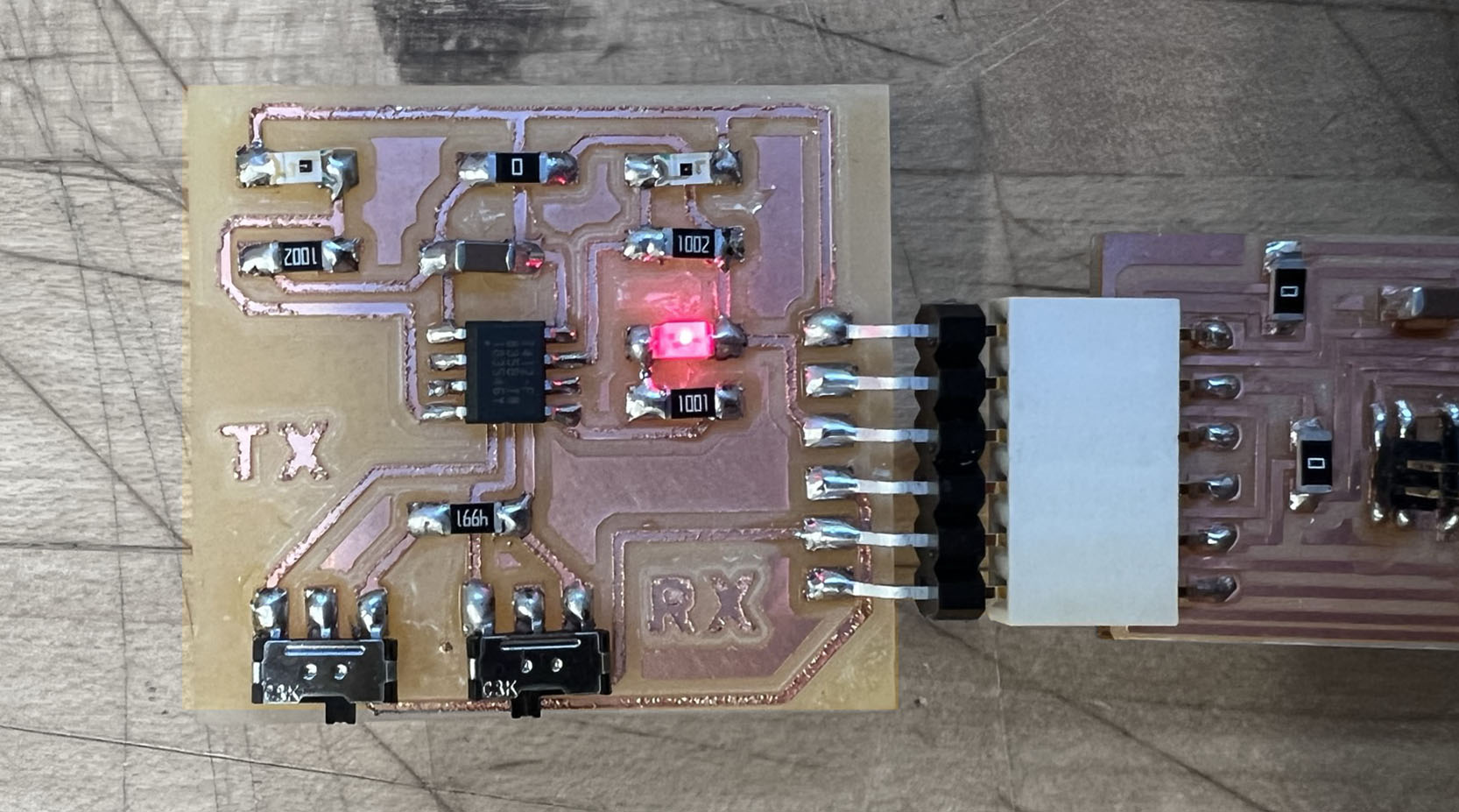
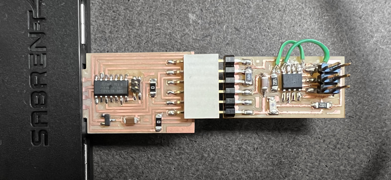
I made a board with two phototransistors with LED and switches to change the connection to UPDI pinout to RX -> TX, TX -> RX to communicate.
I could not figure out how to communicate the ATtiny board through the D11C USB board I made earlier. I was able to program the board but did not communicate.
I made a mistake that I soldered phototransistor green line goes to GND, same as LED, but light sensor's green line should face VCC.
The blue line is one phototransistor that was flipped, so it was not working correctly. Also, it was funny that LED was behaving like a phototransistor, better than a misconnected light sensor.
Other than that, the board worked fine. Thanks to Calvin, I learned remapping to compare two different input streams.
Other than that, the board worked fine. Thanks to Calvin, I learned remapping to compare two different input streams.
Before moving on to the next step for input and output devices, I wish to make a USB board that can program and communicate with an AVR microcontroller so that I do not need an FTDI cable.
- Roland SRM-20 (PCB milling)
- Soldering station
- ATATMEL-ICE
Ki CAD
Mods
Rhino+Grasshopper
Photoshop
Mods
Arduino IDE
Files