Kim
0
1
10
11
100
0101
0110
0111
1000
1001
1010
1011
1100
1101
1110
1111
final
I was able to program a simple Arduino example to a board from the previous week thanks to Laura, Zach, and Calvin. I noted every steps and struggles in Week3. However, I was doing almost everything on the shop computer and hadn't set up my laptop for future work. I started this week by repeating everything I learned from week3 on my Windows laptop.
This is my message to TA and people who know about programming and the electronic world.
I had a hard time getting a message: "Error: more than one debugger found, please specify a serial number" but thanks to Neil's quick response, I could bootload my old and new boards on my laptop.
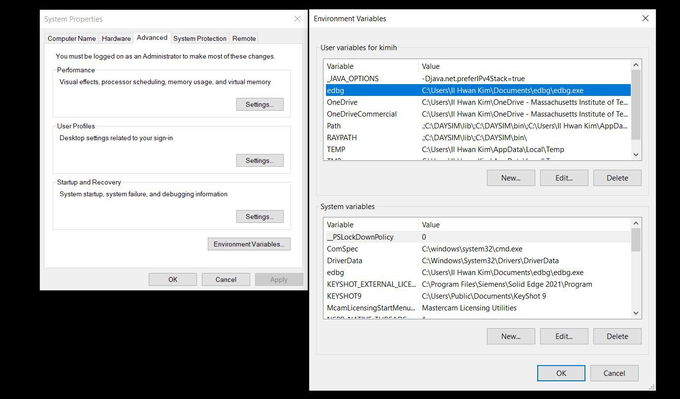
One thing I could not make it work is adding edbg path to Environment Variables. I was following Laura's instruction but my cmd does not read edbg command straight so I had to call edbg and bin file folder path.
The next step was adding the board manager to Arduino IDE. I was using one I got from Git, but it seemed outdated. It worked fine when I was using Zach's new URL.
"https://raw.githubusercontent.com/qbolsee/ArduinoCore-fab-sam/master/json/package_Fab_SAM_index.json"
I am proud of the working Frankenstein blinking board from the Electronics Design week, but I want to have a clean-working board that proves that I understand and mastered simple PCB design and milling. So I decided to make another board with more LEDs! I was thinking of using the Servo motor that I will use for my final project, but my programming is worse than 5year old kid, so that I will go simple
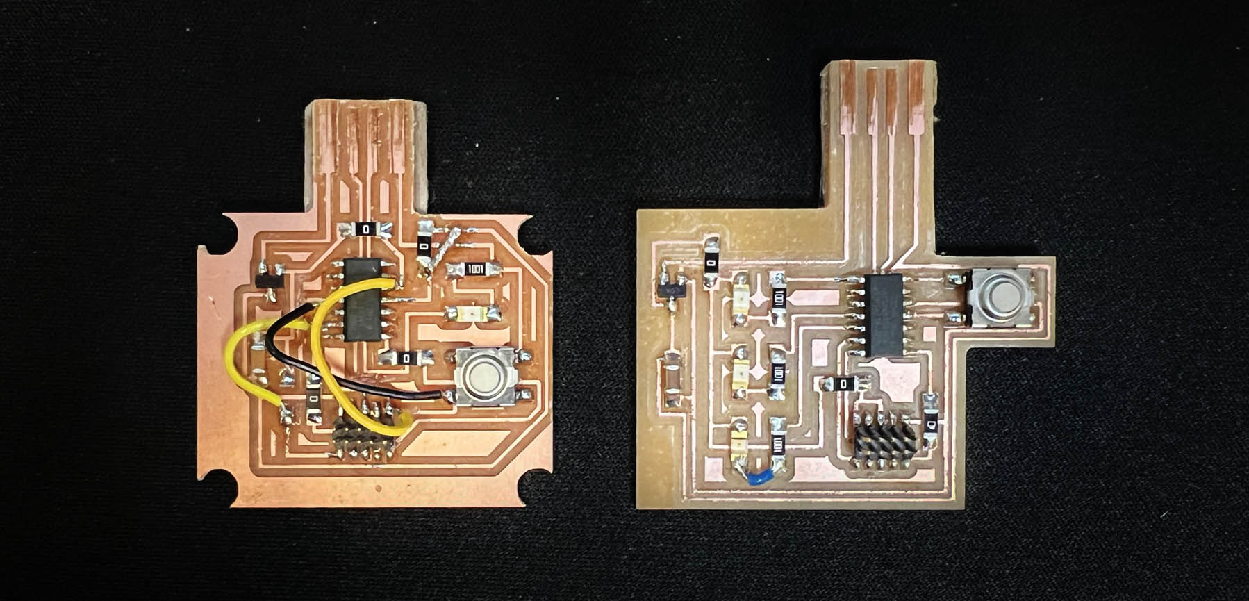
After milling and soldering my new board with R-G-B LED, I realized that I didn't use a pull-up resistor on connection mistake. However, Thanks to Zack, I learned D11C has an internal pullup/pulldown resistor.
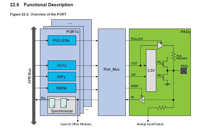
Bit 2(PULLEN: Pull Enable) enables the internal pull-up or pull-down resistor.
THis is serial of RGB LED dimming activated by button. I'm still working on different light patterns with a button pressing pattern.
I was learing a lot from following steps of simillar project from "Arduino Project Hub"
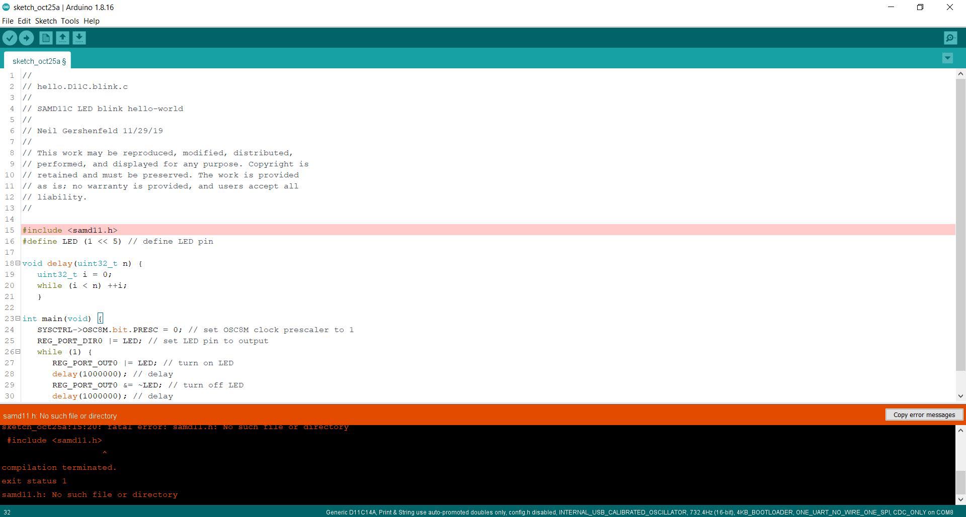
In addition to TA and friends' help, I tried to use C as Neil suggested for faster loading, but I couldn't go further. I can stay where I'm at and learn programming more.
Electronic board making
- Roland SRM-20 (PCB milling)
- Soldering station
- ATATMEL-ICE
KiCad
Inkscape
Photoshop
Mods
Arduino IDE
Files