Kim
0
1
10
11
100
0101
0110
0111
1000
1001
1010
1011
1100
1101
1110
1111
final
Continuing last week's work, I wanted to make the output device work with a phototransistor.
This week's goal was to operate a stepper motor, which I will use for my final project, based on input values from a phototransistor.
However, like every week, it didn't take long to learn how difficult it is to upgrade my board with new devices and functions.
From the half success of this week's goal, I could make the scale model move. This small success brought my motivation back to work on the final project.
The video shows that the stepper motor pulls the wire and makes mechanical arm moves, but I could not change direction.
Also, I was testing a few different Arduino example codes, and only one step at a time works consistently but not other functions. I could not find what is the problem yet.
I wanted to add a motor controller over my phototransistor board with ATtiny412, but I needed more pinouts for the bipolar H-bridge.
However, I found AVR microcontroller is easier to use and faster to code, so I didn't want to go back to ARM processor.
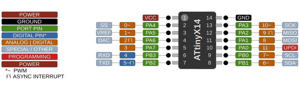
I found AVR microcontrollers, ATtiny 1614 and 1624 in the Arch shop, with more pinouts. I tried to figure out the difference between PA and PB from the datasheet, but I failed to understand the difference between them, and I assumed they behave the same way while designing the board.
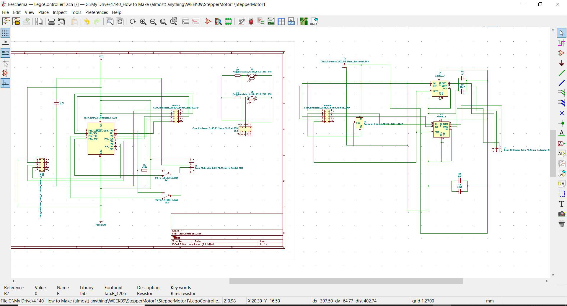
I designed a board with ATtiny1614 and motor controller A4953 with a programming/communication switch and phototransistor.
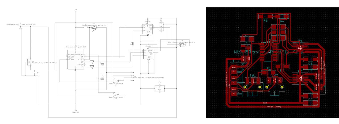
I was trying to calculate the width of the PCB route for the higher voltage paths by using PCB Trace Width Calculator, but I end up using slightly wider than the Neil's example's width(0.76mm).
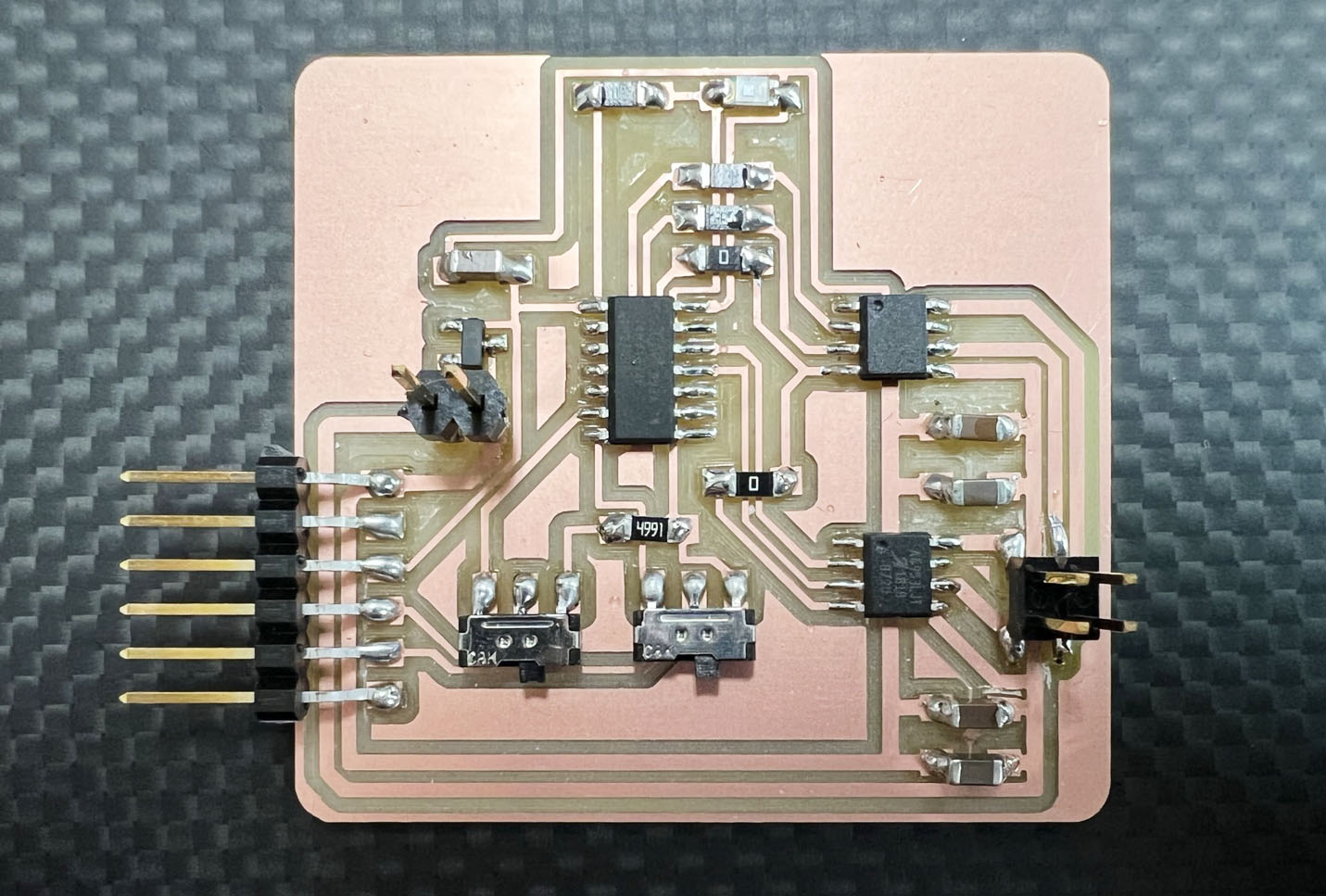
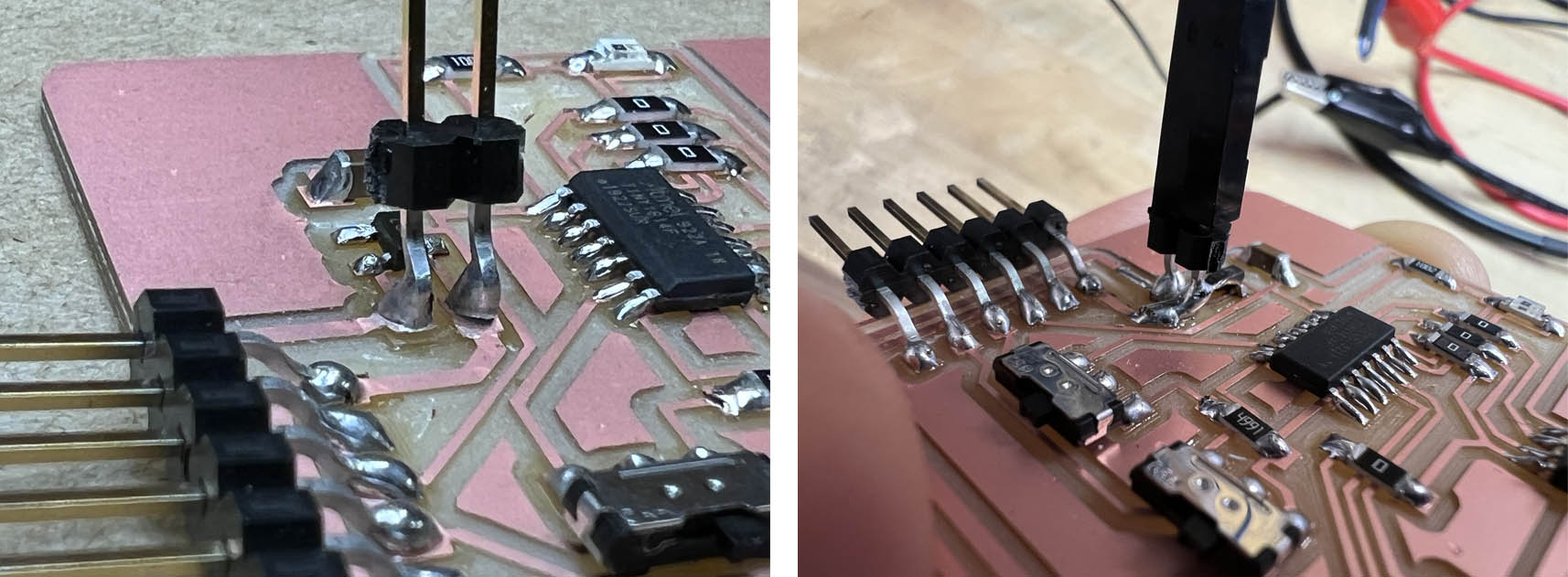
After milling and soldering the board, I tested to program the board with my FTDI cable.
I changed the board from Arduino IDE to ATtiny 1614 from the MegaTinyCore board library.
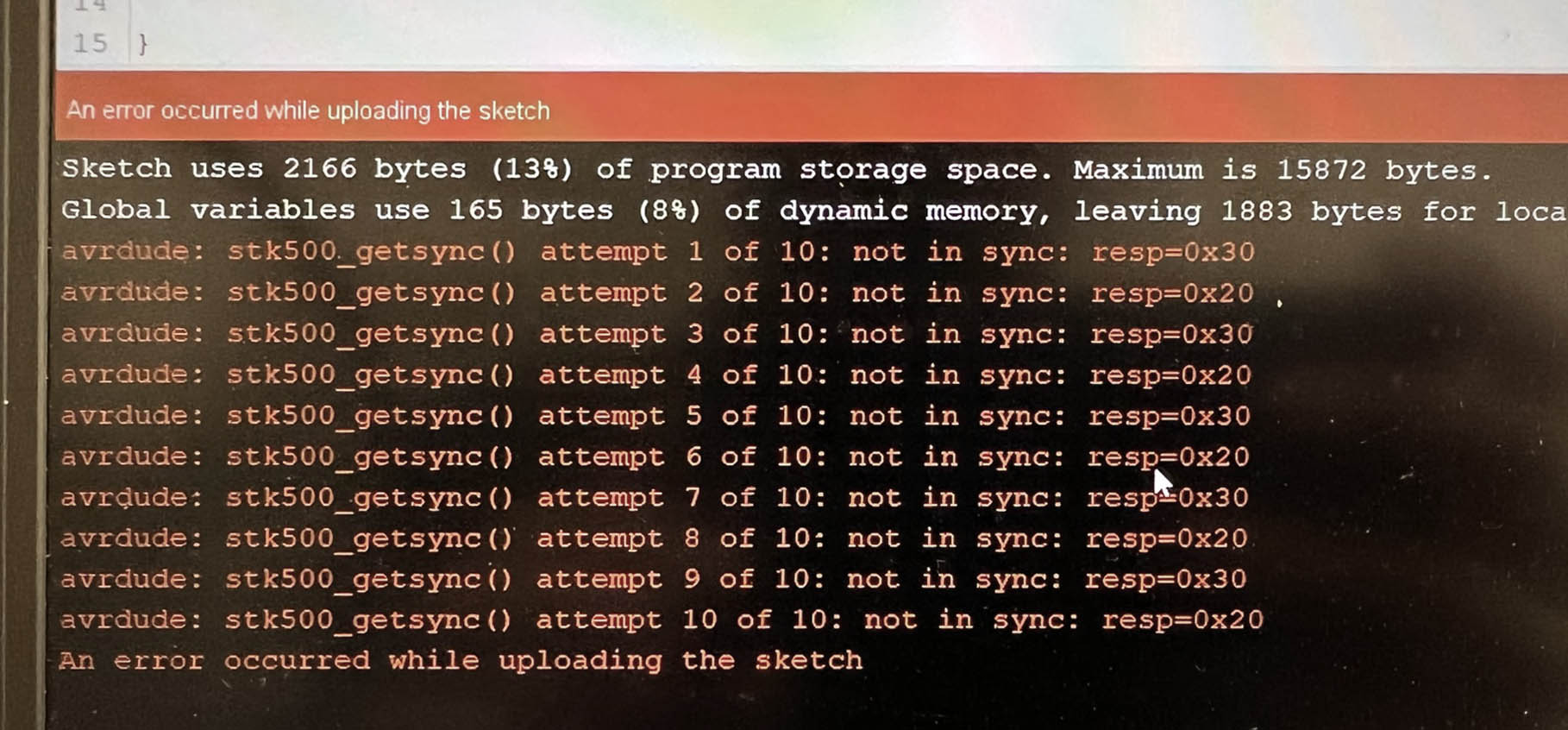
However, I could not program the board with the following error message.
It is always stressful when the new boards are not working with unexpected problems because I have no idea what went wrong, from the board design to milling, soldering, and Arduino IDE setting.
I started doubting my board design, but I could not find anything that could cause such an error. While I was making a simpler board with my familiar old friend ATtiny412, my friend Demircan helped me find the IDE setting problem, choosing the wrong ATtiny1614. I selected ATtiny1614 Optiboot.
I tried to understand the difference between Optiboot and regular one but failed. Optiboot seems like supporting more extensive sketch libraries and extra code space, but I don't know what it gives me an error.
Anyway, I can move forward.
I programmed the test version of changing steps of the stepper motor based on mapped input values. I could check the phototransistor is working fine, even though the value is not consistent. I need to work on that.
The bigger problem is the microcontroller gets very hot when I connect to my computer with FTDI cable. I had to program and pull out the cable every time quickly.
I have no idea what went wrong. The datasheet says ATtiny1614 supports a voltage supply from 1.8V to 5.5V, which might be fine with a 5V supply from USB to FTDI cable.
The board eventually got toasted the next day. I saw the smoke coming out from the microcontroller and not working after. I tried to replace the microcontroller and continue working, but after a long tiring day, my desoldering was not delicate enough to save the board. I ripped the copper route.
I will make another board which I will explain later.
Before I fried my board, I had another issue with vertical pins. I found that using a jumper wire over a small board through a vertical pin is not ideal. I accidentally pulled the wire connected to the vertical pin and ripped the copper sheet attached to the PCB.
I could put more solder to reinforce and brace with a pin, but I need to think about a better way to make stronger and stable connections.
Another problem I have to solve is to make my 3.6V stepper motor move. I bought a 17HS4401 stepper motor, but I could not move this motor while I could make a 12V stepper motor move.
The next board I am working with Demircan Tas is separating the microcontroller, sensor, and motor controller boards. It will give me the freedom to change sensors and motor controllers without wasting microcontrollers and make everything from scratch.
- Roland SRM-20 (PCB milling)
- Soldering station
- ATATMEL-ICE
Ki CAD
Mods
Rhino+Grasshopper
Photoshop
Mods
Files