Kim
0
1
10
11
100
0101
0110
0111
1000
1001
1010
1011
1100
1101
1110
1111
final
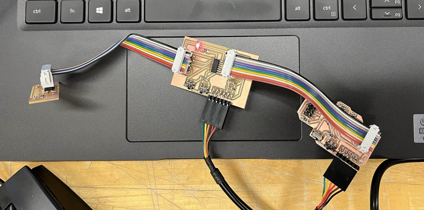
I started this week from an unfinished work from the last week. I finished making three boards, a processor, motor controller, and LED, connected to 2X5pin connectors. Demircan and I matched the pin, GND, and VCC connections to share boards to connect each other's processor board.
After testing separated boards are working, I tried few networking with Demircan.
We made a chatting communication through each other's ATtiny1614 board, sending and receiving messages to the other board. The idea was to send and read the other's messages using SoftwareSerial.h library and print my message on my serial port from echoing.
However, echoing did not work correctly, and it's missing characters or giving errors, unlike reading other's message was successful.
I named this 'Lego Board,' which can connect any board with different functions to the ATtiny1614 processor. I tested the sensor and motor controller, and both works.
I could not make the stepper motor move properly yet. It moves with a simple rotation code, but I failed to operate with the Accelstepper library or mystepper library. Without libraries, moving the stepper motor to the position I want is not easy for me.
I was working with Demircan to get values from the phototransistor. Sensor data comes to my ATtiny1614 board, is sent to Demircan's board, and is read by serial port.
Values I'm getting directly from the phototransistor range from 0-1100(here, I have two phototransistors but use one for the test).
Still, Demircan's board is getting Low or High, digital signals, and I have no idea why it's transferring to digital signals.
The screen on the right side is my screen, showing an analog signal getting from the phototransistor, and the left one is Demircan's board receiving High/Low signal getting from my microcontroller.
With the same board setup, we lit LED on microcontroller boards depending on brightness. As you can see in the video, the left board(my board) light up if it's bright, and when it's dark, the board on the right side(Demircan's board) lights up.
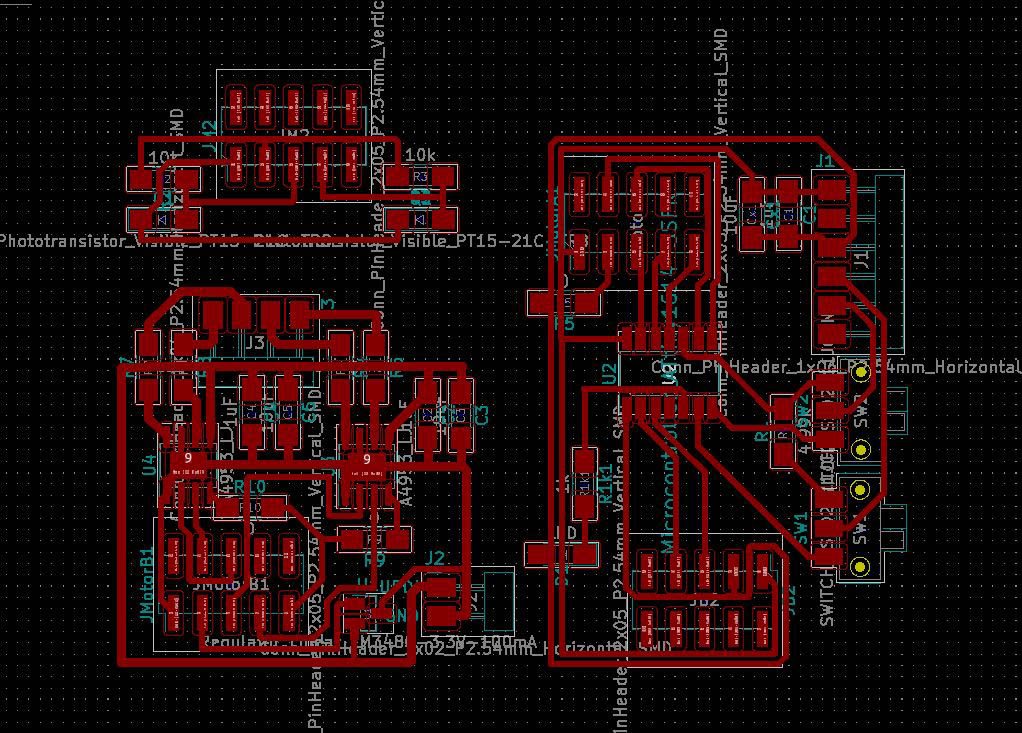
I wanted to add a motor controller over my phototransistor board with ATtiny412, but I needed more pinouts for the bipolar H-bridge.
However, I found AVR microcontroller is easier to use and faster to code, so I didn't want to go back to ARM processor.
I found AVR microcontrollers, ATtiny 1614 and 1624 in the Arch shop, with more pinouts. I tried to figure out the difference between PA and PB from the datasheet, but I failed to understand the difference between them, and I assumed they behave the same way while designing the board.
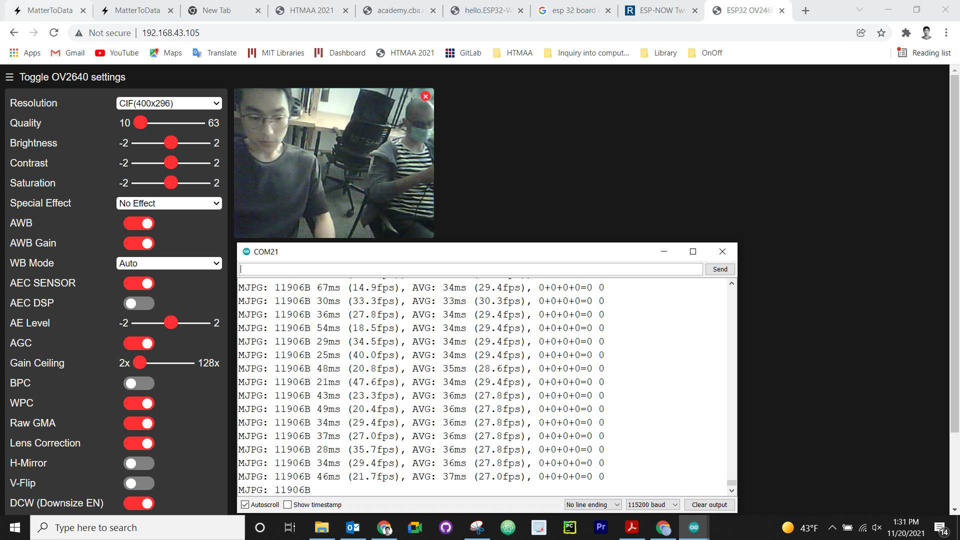
This time, I went wireless. I made Neil's ESP32CAM to 6pin board and followed Neil's guide to program the board.
I found it weird that the hotspot from my iPhone does not allow me to connect ESP32CAM. I was able to use the hotspot from an Android phone.
I failed to use School wifi and hotspot from my iPhone. I saw someone using their iPhone hotspot, so that it might be possible to use my hopspot, but I have no idea why it's not working when I tried to connect.
After struggling with wifi, I could be able to connect ESP32CAM. I enjoyed playing with the built interface to see what I could do with this cam.
I should push harder, but I took the easy way to spend more time working on stepper motor control, which I've been failing for three weeks.
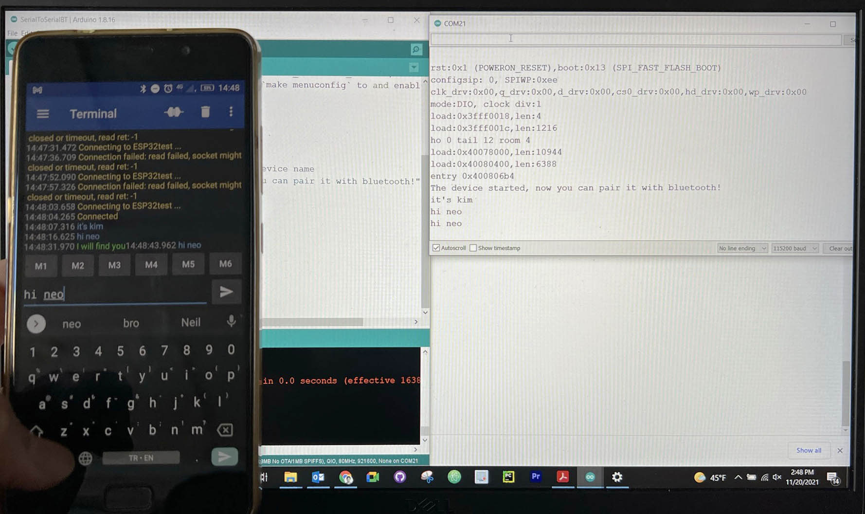
I borrowed an andoroid phone to use serial bluetooth terminal application. I was able to connect my ESP32CAM and send a message back and forth.
- Roland SRM-20 (PCB milling)
- Soldering station
Ki CAD
Mods
Photoshop
Mods
Files