Final Project
Integrate most of the fabrication processes learned into a single design
Background
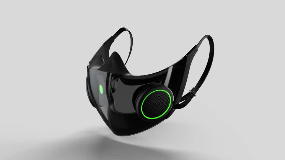
(Image 1) This is an image of some concept art from Project Hazel
Practicality. I didn't want another project ending up in a box somewhere that I eventually throw out when moving. What would I actually use? It has been a pain in my side ever since the pandemic that people keep telling me to speak up when I am wearing a mask. I know I mutter a lot but damn. So I sought out to create a mask that essentially amplified a voice. There were a number of design principles I could optimize for and features that I personally could desire, but I don't like designing for myself. I've done that in the past, especially in my first few games as a amateur dev, and it just doesn't work out. I needed a living, breathing audience to facilitate the iterative development cycle approach I take towards design. So after a few observations in my immediate surroundings, I decided to make students my audience.
Often when a professor asks a question in a lecture hall and a student responds or a student asks a question, it is difficult for the professor, and even some of the other students, to hear the question. This audience made sense and later informed some futher design decisions down the line (yes this is an intro revised in hindsight). But with this first notion of an audience and idea I set out to design my final project.
My initial approach sought to make a modular, cost effective, and ergonomic design. Before development, I took a look online to see if the idea was in the process of being commericialized. Turns out a few companies have but their price points are either too high or they have yet to scale to production capabilities. Once such inspiration is Project Hazel made by Razer which consists of a N95-based design, a built-in amplifier, and a transparent look to allow for facial expressions.
First Design
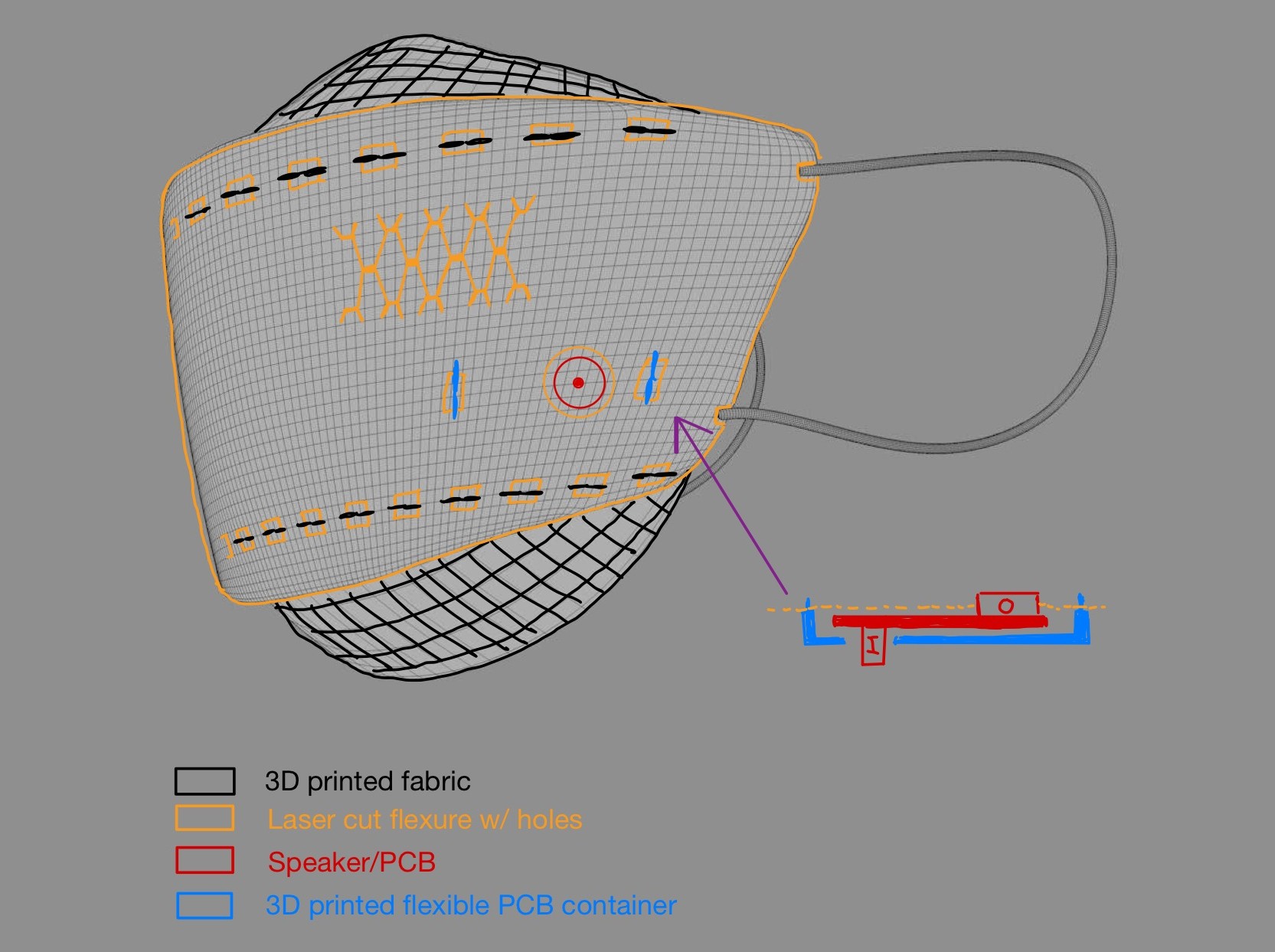
Outside of what is already shown in the above image, the PCB itself will be flexible to abide by the curvature of the lasercut flexure.
This will be made possible by vinyl cutting the copper traces and placing them on a flexible material. The PCB will also likely need to
be double sided to enable I/O device layout shown in the side view of the PCB container. The PCB will also be usb powered for safety
reasons and to reduce development time.
The design uses 3d printing, laser cutting, electronics production, vinyl cutting, and potentially molding/casting for a nose bridge not
shown in the sketch render. In regards to networks, I originally thought about interfacing with an app for volume/pitch control and other
features, but adding bluetooth seemed like an unecessary amount of development time. Instead, I have pivoted to buttons on the PCB
for controlling volume and the like, which is not shown in the render.
My anticipated development challenges include streamlining the upper and lower 3D printed fabrics production, balancing the flexibility/strength
with the flexure, and reducing latency in the amplifier.
Nose Bridge (Update 10/27)
Initially, I had thought that I might want to mold/cast a metal nose bridge. However, in week 6 I made a 0.01 inch thick batarang casted in the only metal we have (i.e. bismuth alloy), and found that the metal was brittle and not at all maleable despite its relative thinness. Any thinner and the molding/casting process would be a nightmare from my experience or improbable (e.g. the oomo mold could fail at a certain thinness) so I need to pivot to another process. I'm currently thinking about testing the retention of some printable flexible/malleable material.
Test Board (Update 11/3)
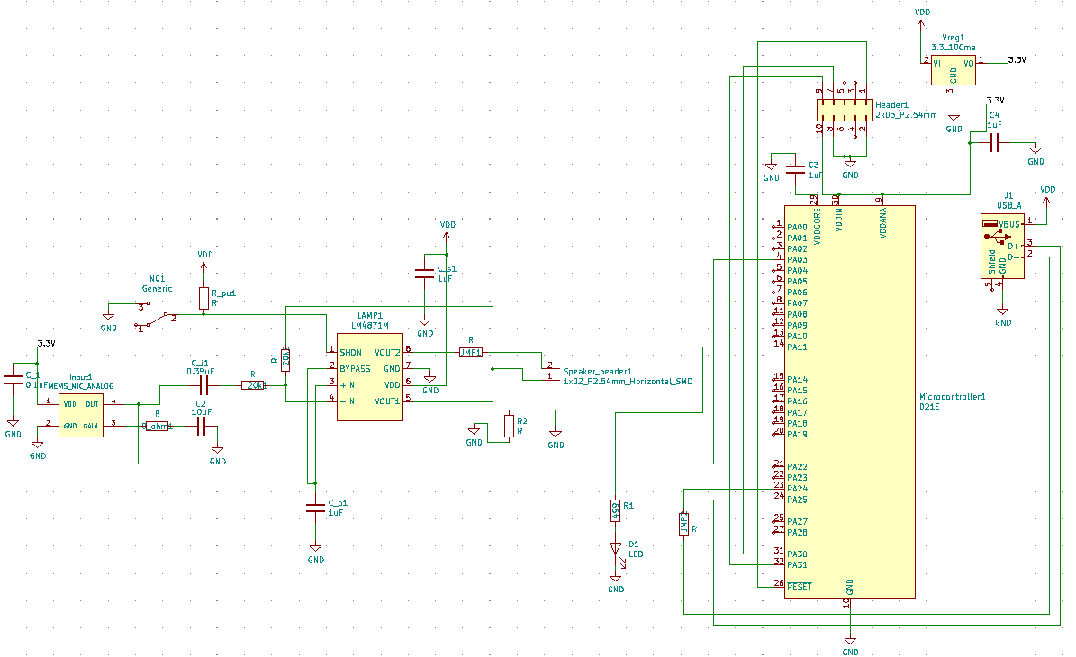
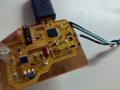
(Image 2) This is the schematic for a test board, which is actually the board I made for week 9/10
This is the schematic of a test board for my final project board. Essentially it is a mic -> LM4871 -> speaker. The attached d21e does not process any data as it would introduce error in the signal upon reconstruction and introduce delay via computation. The d21e was attached for week 9/10 to allow for non-critical data processing. The purpose of this board was to fulfill week 9/10, but also tune the board. For example, what R and C values worked best for the internal gain on the analog mic? What R_f/R_in values were needed for the gain on the LM4871? Where was the main source of noise and can it be solved with a bandpass? How bad is the feedback between the mic and speaker?
Once the board values are tuned, I should be good to go head and make the board flexible by cutting the traces on the vinyl cutter, make the board double-sided, and shape it inside the casing of my project.
Pivot - Clip-On Amplifier (Update 11/13)
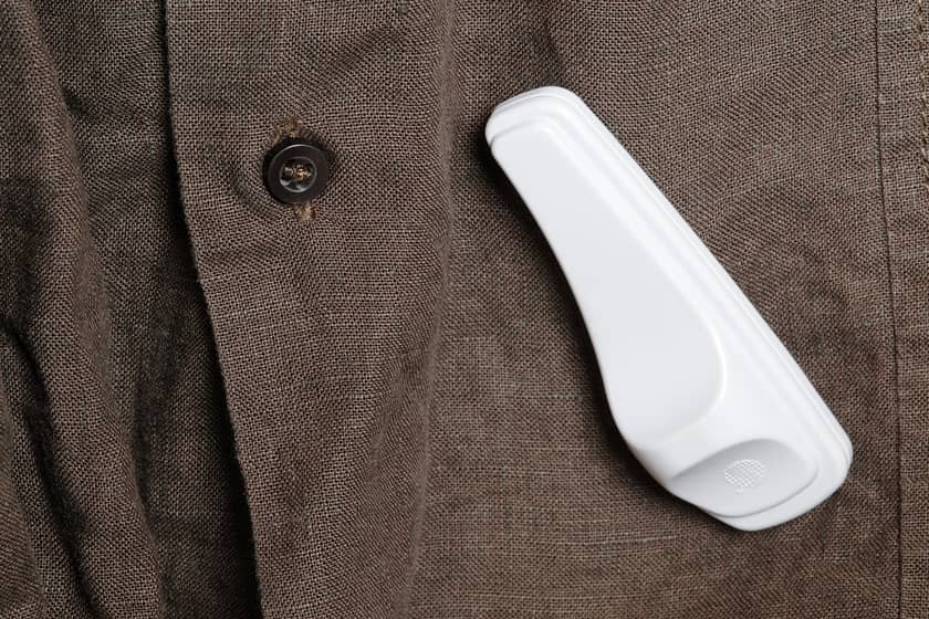
(Image 3) This is an image of a clothes security tag but one could image a similar module with an in-built amp hanging off the side of our masks
If my project was a mask but wasn't medical grade, then no one would buy it. At that point, I would have to market the mask as a cover on another mask. However, a cover or "double-mask" would likely be uncomfortable or cause difficulty breathing. Rather than design the mask to be medical-grade (an arduous task to undertake), a friend made a brilliant suggestion when they referenced clothes tags.
As of now, I am pivoting to a mechanism with an in-built amplifier that simply clips onto an existing mask. This design choice I believe is the most practical as it minimizes the barrier of entry while preserving the identity and comfort one may find in their own current mask (e.g. perhaps someone made their own mask with their mom and would like to stick to said mask). The cons that I immediately see primarily consist of a lack of technical complexity. I am going from a full on mask with a 3-d printed mesh like material and a laser-cutted flexure to a single clip and amplifier likely consisting of 2 processes - 3-d printing and pcb fab. Nevertheless, I believe it to be the right decision and will move forward this pivot. I don't want to switch ideas for the sake of technical complexity as I do not believe a project is better if the less people understand it. The new design focuses are as follows: minimizing weight (prevent uneven load), reducing bulk (the volume should be minimized to avoid aesthetic changes and improve ergonomics), and remaining cost effective. Since the board noise profile will largely determine the casing part of the clip design, I am focusing on the mic-speaker tuning first before ideating any casing designs.
Sodering the Test Board
(Image 4) After many sodering surgeries, this is the final board (the test board became the final board as explained later)
Many wire surgeries had to take place for this board to come to life. Here is a brief recap of that journey.
At the end of week 11, I was wiring some wires from an rn4871 board to my d21e board and I burned some key traces clean off the board. The solution was to lay some thin wire down and make clean, purposeful soder bridges. This was absolutely non-trivial and even gave Anthony some trouble.
Then came the weird values that my reference schematic called for. I rounded most of the resistor values, but I decided to use the 0.39uF capacitor. However, as this was not a common capacitor they did not come in a standard size and I had to soder the wires directly to the pads which was a little awkward but after some patience, I got it.
Once I had the main components sodered, I was ready to test the speaker, but as I was sliding in the leads, I broke off the header as it sliced into my hand. There was a little blood but nothing crazy. I slapped on a band-aid and got to fixing it. Unforunately given that a whole component came off, it was a little more complicated. I glued down the header, made soder bridges to the traces, and then encased the whole debacle in glue to solidify the surgery (glue is noncondutive so adding more cannot harm the project in any way except maybe weight and lack of mods).
Turns out I also misaligned and possible burnt the microphone when I was using the glue gun for the first time so I had to replace the mic and place a new one using the glue gun. Advice? Stick to 670 if you are a beginner, stay about 1.5 inches away from the component, and look to see small excess soder coming out the sides.
Ok time to test the speaker! I can't hear a thing! This was likely due to the gain on the lm4871 amp being set to 1 intially. The differential gain according to the lm4871 datasheet is proportional to Rf/Ri which are resistors labeled in the reference schematic (see week 9/10 for the reference schematic), so I increased Rf by an order of magnitude. Ok now I can hear the speaker! And it is a crisp, clear sound! No noise! Unforunately, the feedback is atrocious, so this means I increased the gain too much. I then proceeded to reduce Rf slowly from 499k to 477k to 430k until the feedback was reasonable. I didn't want to reduce Rf too much because I still wanted to maximize the amplification.
It was at this point Anthony noted that going the flexible route with vinyl cutting the traces won't work because the d21e traces are too small. Also since feedback was tolerable and the noise was pretty nonexistent on ground level chances were good that I could use this test board as the final board as opposed to making another board with an analog filter. However, rather than have the mic on the inside and speaker on the outside, I would have both component on the outside. This was for two reasons. Firstly, the size made putting the board inside the mask highly improbable and likely uncomfortable. Secondly, while the feedback was minimzed to a degree when the speaker and board were held apart (about a foot), the feedback when both components were directly behind one another, was unbearable. The solution was to have the board on one cheek and the speaker on the other cheek. The physical seperation would also help in minimizing feedback. After placing, both components on my face with my mask on, the sound was still clear with little to no noise despite the added mask interface so I was cleared to use this test board as my final board. Now I needed to design the clip.
Clip Design
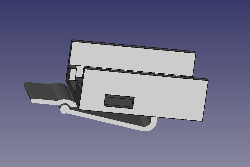
(Image 5) Final cad design of clip
Designing the clip was nontrivial for a few reasons. 1) The "joint" (whatever mechanism kept the clip attached to the mask) needed to be strong enough to support the weight of the clip and cargo (speaker was heavier than board) 2) The mechanism needed to be reversible and relatively ergonomic 3) One clip would house both the speaker and board (the selected speaker was out of convenience so designing a custom clip for this speaker didn't make sense in the long term, and I wanted some aesthetic uniformity for demo purposes)
I first thought of a paper stack clip or a similar device that used a torsion spring but I quickly realized that designing a 3-d printed torsion spring was much too difficult. I decided to then divide the design into 2 parts: 1) the joint (as defined earlier) 2) the case (the part that housed the speaker or board in place). I first focused on the case because there wasn't any reference so I could tinker away on that while my brain thought of ideas for the joint.
The case alone was a non trivial design because I was designing without a cover. With a cover, the "cargo" of the case could theoretically be loose inside bouncing around but it will be fine because there is a cover preventing the cargo from falling out. Remember that the case was going on the side of my face so the open face would be open along the horizontal. The reason I chose to design without a cover is because I didn't think I would have the time to redesign around the acoustic changes due to a cover.
To keep the cargo in place without a cover, I had to use some press-fit idea or an adhesive source. Adhesion of any kind is usually frowned upon so I tried my hand at press-fit using the board's dimensions because the board for the most part was bigger than the speaker (the speaker was technically longer but I was comparing it to the main housing; more on this later). By designing a tight fit around the board and a usb slot, the board should stay upright even with the aforesaid open face. However, having a usb slot meant that I needed to have enough room to angle the board into the slot. I made some rough angle calculations based on the height of the side walls. I made the side walls (side being the smaller side), less tall than the top/bottom walls because I wanted to make the sliding of the board into the slot easier as well as make holes for the connecitng wires between the two modules. To account for the total length of the speaker, however, I made the side wall holes bigger to account for the total width of the speaker.
As I was making this case, I was thinking about the joint and I kept thinking about a pressure-based joint so rather than it be mechanically motivated by a spring, I figured it could be mechanically motivated by increasing tension with the plasticity of the material. I was looking up images related to this idea and came across a money clip. I took a look at the idea and read a little about the pros and cons. The biggest pro is the simple design. The biggest con would be a lack of tension created by typical designs with 3-d printed materials. The solution, as provided by a website (not original), is to create a dip in the surface of the clip so the resting position of the two faces is intersecting meaning the sandwiched material has to go around the divet creating more friction. Please see this wonderful tutorial for more details.
Once making the money clip and combining it with the casing, I had the full design as picture above. You can find the step file here.
Digital Feature and Assembly
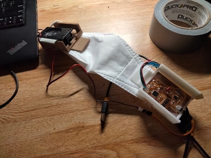
(Image 6) Final Iteration (led strip taped to the side of the upper wall)
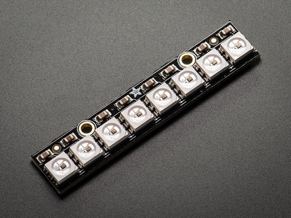
(Image 7) Neopixel Individually addressable LEDs by Adafruit
Since I wasn't doing any analog filtering, my project was definitely lacking some complexity and Neil wasn't shy in voicing this concern. So I had to add a digital component. However, I didn't want to add one just for the sake of adding one. Someone had said to animate facial expressions but this would detract from the main message of a discreet encapsulated clip-on module centered around voice presence. I then thought back to the idea of professors struggling to idenitfy the speaking student. What if there was an led indicator that responded to the level of amplitude in your voice? This sounded pretty good to me and could even possibly help small mircocommunications (i.e. people discerning when someone else stopped talking/is about to start talking).
One of the benefits of this feature was that it didn't require too much by way of on-board components and it wasn't too complicated programmatically. I just needed to read the analog signal and divide up a region of values into the number of leds I had, correspond each region to an LED, and turn on the number of LEDs corresponding to the number of activated regions. The code could be found here. The hardest part about this code was fine tuning the region of values and for this I just used the serial monitor to 1) find the value for silence when I had my mask on and the mic was near my mouth and 2) find the value for the rough max amplitude of speaking loud with my mask on.
To directly turn on the leds, I used individually addressable neopixel LEDs as provided by Michelle and the Arduino Neopixel Library.
Once I added this feature to the project, the assembly was straightforward. The 3d printing of the clip went as planned (~4 hours per part though) with no adjustments necessary and the board fit just right. I couldn't make the cover (as I will explain below) so I used tape to keep the speaker in place. The only slight annoyance that I didn't really account for was the weight and torque of the usb cable. Given it is usb powered as a temporary solution, the cord drags the clip down on the side of my mask. I decided to minimize this torque by having the usb slot point down and have the cable plug-in from the bottom. While this minimized the torque, it reduced the strength of the joint by a lot due to gravity, which I found on demo day, so I had to unforunately hold it in place quite embarassingly. The demo worked but wasn't particularly impressive by the crowd's stark lack of response relative to those prior.
Extensions
As mentioned earlier, this project lacks a decent amount of technical complexity but there are many ways to easily and vastly increase the technical complexity and some are outlined here.
Firstly, a cover. A cover design would pretty straightforward, but one that would preserve acoustics and be mechanically stable would be a little more challenging in my opinion. Secondly, a battery. While adding one to a circuit is straightforward, the thermal testing needed for a battery in close proximity to the face I think would be a little challenging. Thirdly, developing a single module as oppposed to a two module device I think would be challenging as it would likely involve a bandpass filtering high frequency feedback as well as a means to mitigate breathing frequencies which might prove much more difficult. Fourthly, developing overall smaller components would also prove to be difficult, not because of the sodering, but designing a small and manufacturable board is something I have yet to attempt to do. Also this would likely require using a different speaker which would likely change the noise profile and tuning previously done. Lastly, a different material or clip design altogether to improve the ergonomics as opposed to a pla money clip would be a nontrivial redesign.