Week 2 - Laser Cutting
Design, lasercut, and document a parametric construction kit
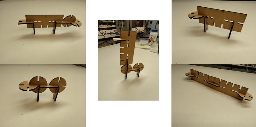
(Image 1) JIgsaw animals from left to right and top to bottom: beaver, ant, llama, sheep, snake
Note from Author
Hi reader, if you just started to peruse this website and want a chronological recollection of my journey through making I would suggest first looking at my other weeks starting with "Week 3 - 3D printing" because I ended up completing this week alongisde my final project at the end of the semester. Why? It's a long story but I was forced to join the class late and had to make-up this week later in the semester when I had time, which was during finals prep week. Thanks!
Idea
Have you heard of Pictionary? The game where a player chooses a card with a short description (typically one word) and draws it as their team members try to guess what the card said? Ok, now think "Construct-ionary". A player chooses a card but instead of draws, they build! They build with small generic parts from a smalls set of possible pieces and their team members try to guess what they are building!
As a game developer, I love thinking of games, playing games, and analyzing games so when Neil added to the assignment description that it can be "assembled in multiple ways", I took that quite literally and sought out to create a game around that primary mechanic. Turns out animals seemed to be a topic that was pretty easily abstracted so I sought out to design a small set of parts that were easy to use and can generalize to a large set of animal designs. This small animal-themed set I designed serves as a Proof-Of-Concept for Constructionary.
Design
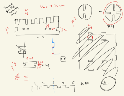
(Image 2) Sketch of design in GoodNotes

(Image 3) Parametric CAD design of parts
Intially, I looked around online at 3d jigsaw puzzles to gain inspiration for how typical 3d Jigsaw puzzles were made (e.g. what did 3d jigsaw puzzles look like?, what physical abstractions did they make?). I stumbled upon a 3d jigsaw puzzle giraffe geared towards kids. The neck piece (later became p1) inspired me to design a part of this very functional piece. Then the idea of an alligator hit me which could easily be created from this main center piece. But with a big piece and lots of linkages, I needed actual linking parts, so I sought out to create a small linking appendage (later became p3). Then, I also wanted to have some bulbous part that could serve as faces or round body parts or even as abstractions of whole torsos, legs, or tails. This part later became p2. With this three parts I decided to futher ideate animals to see if there was a hard cap on the number of animals I could reasonably create with this three parts. I realized I wasn't using some parts to their full potential, so I made p2 have 4 symmetric slots as opposed to 2 and added cutouts in p1 to allow for press-fit joints. I added these extra features to further increase the possible design space and allow for more ways of play/building without adding too much complexity (imo; I didn't do any paper playtests because I wasn't doing a full game development design cycle for this short project). With these general shapes in mind, I sought out to CAD my parts. Little did I know, that balancing dims across parts was going to be the hardest part about this project.
Keep in mind that when cadding I was trying to support at least 4 animals: cow, snake, giraffe, dragonfly. For those that exist in image 1 (i.e. cow -> cow/sheep and snake and the giraffe -> llama), those were roughly the shapes I had envisioned my parts creating. I will be referencing these shapes as they led to the following design constraints:
- C1: p2 circle needed to be size of p1 height to enable snake (snake to ratio needed to be 1:1 for aesthetic reasons)
- C2: Cut depth (d) needed to be equal across parts to provide best joint/linkage (there were also some implicit constraints on d such as d being boudned by some function of p2.radius and the omnidirectional symmetry, cuts into p1 were also of depth d so that affected the aesthetic of all animals using p1, and more)
- C3: d:p2.radius needed to be as high as possible to allow for spherical abstractions
- C4: p3.length = 4*d to enable 2 spheres linked via p3 to touch (this was for aesthetic reasons such as creating torsos of connected spheres)
- C5: d >= width of material (w_m) because of slot joints on p1 (if d was smaller than w_m, the slot joints simply wouldn't work, there wouldn't be enough friction)
- C6: proportions need to be realistic (e.g. leg length of cow will be 2*d given c4 which relative to its body (p1.height) will be 2'' to 0.5'' if p2.radius =2'')
Struggling to balance these constraints and make the shapes relatively small to make the animals cute (also helps in abstracting details) was no easy feat. Especially as one constraint creates more. For example, C6 leads to a clash with C3. If the ratio of d:p2.radius is smaller you get better proportions but lose spherical capabilities, and going too small violates C5. I couldn't possibly remember, fit, or explain properly all the design considerations I made during this semi-hectic and non-systematic design process, but hopefully this gives you an idea of the design hell I went through in designing these parts.
Given the geometry of the material and the symmetric p2 design the highest d:p2.radius ratio is roughly .65 so I went with 0.5 which yields 1'' leg to 2'' body height for a cow. These proportions seemed correct and I simply assumed that realistic proportions in one animal would translate across animals given they are using the same parts. This isn't exactly true but it worked out as shown in Image 1.
The software I used to cad is FreeCad and my step file can be found here
Vinyl Cutter
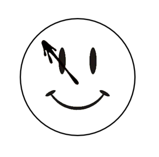
(Image 4) Black and white image of smile design
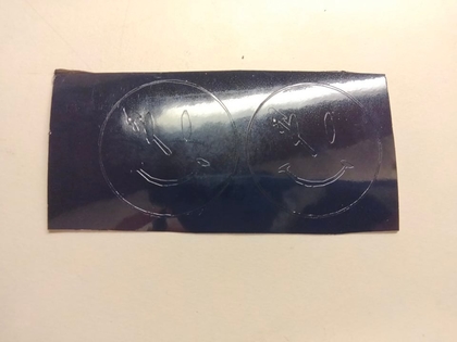
(Image 5) Vinyl Cut Smiles (did not cut all the way through)
The vinyl cutter theoretically is pretty straightforward. Get a black/white image, dump it into mods, make sure the clamp is down and the origin is above actual material, and cut! However, this was not the case for me. I had Anthony and Alec help but they couldn't figure out why my image was being cut only partially. And what is more strange is that the amount cut varied with dpi in a nonlinear fashion (i.e. 300 -> 5% 350 -> 80% and 370 dpi -> 20%). Turning off the whole setup and reconnecting to the mods server appeared to be the only fix and was able to successfully cut the image with a modified dpi (i.e. I changed the native dpi in mods to change the size of the image).
In case you're curious, the design was an original created with some clever editing in powerpoint (yea I am no guru with other photo editing softwares but hey I do decent game assets and designs here and there with powerpoint). The design itself was heavily inspired by Watchmen as I am a huge Rorschach fan. You can get the photo here