Week 9/10 - Input/Output Devices
Add input sensor and read it; Add output sensor and program board
Disclaimer
Last week I was forced to attend another matter, thus I am combining my Input/Output weeks into a single board. Unironically, it aligns with my projected plan (read more in "Plan"). However, I ran into some difficulty in execution of said plan. Essentially, the KiCad Footprint associated with the SAMD21E in the "fab" library has the pads so small and close together that you have to change the footprint. The problem is that only a MOD routing plan will reveal that the D21E pads are shorted together. On the other hand, while tracing you can simply make the traces small enough to be compatible with said pads. Once you find the short in your routing plan, one might try cutting the pads with a smaller endmill. However, because the pads are so small this would mean that all 9 mill traces become 3 mill traces, which is an unusable trace. Hence any attempt at milling would be futile.
Plan
The current plan for my final project is to use a double sided flexible board to amplify my voice. I was going to use this week to test the circuit itself and then later add other features (i.e. flexibility, double-sided). The board will use a microphoone (input device), an amp, and a speaker (output device) as the main components, but what about the programming required in the output week? Speaking morse code. I will say a letter/sound to the mic and based on some frequency, identify the letter and thus convert it to a series of dots and dashes. These dots and dashes would then be displayed on an LED. I like this plan because it is more streneous on the software side given the low hardware investment and actually utilizes the analog wave.
Note I said "some frequency". The reason I say this is that while certain groups of sounds are pretty distinguishable like consonants v vowels, other distinctions such as between vowels would be harder (I can always scale it down from idenitfying 26 letters to a smaller identification scheme). To rectify this, instead of just saying the letter, I will be either saying the sound or dragging out the letter. This should provide enough distinction in peak frequency to serve as an identifer of the original letter. I will be using a software called Praat to idenitfy the peak frequencies of my own speech. In code, I will be using a FFT implementation to extract the frequency from my incoming analog signal.
Board Design
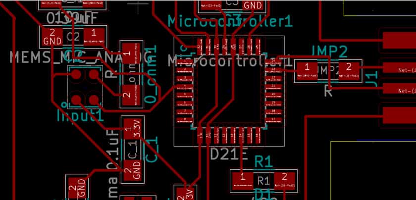
(Image 1) A general audio amplification circuit from the LM4871 Datasheet
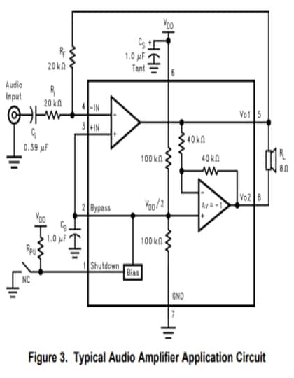
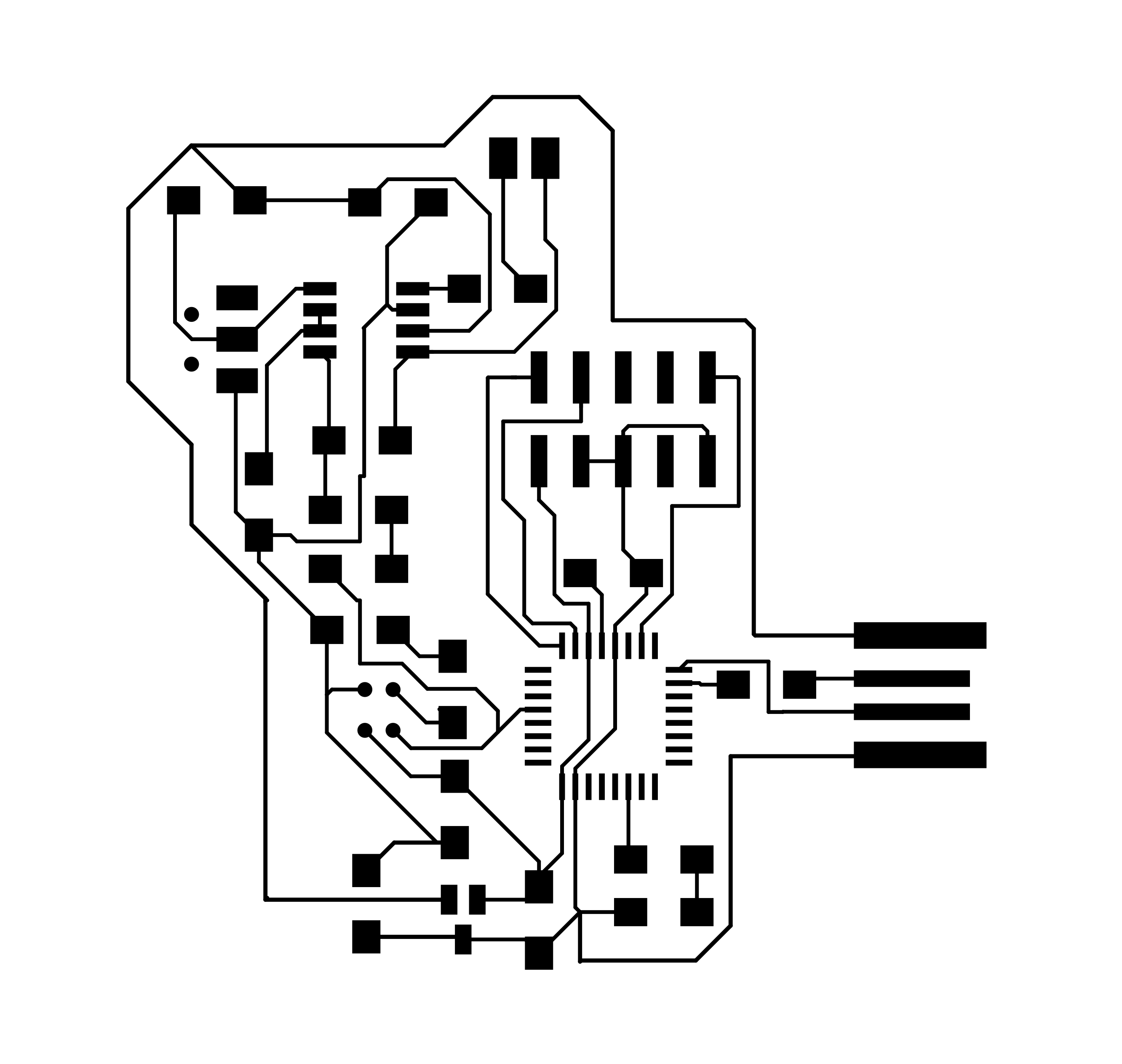
(Image 2) SAMD21E Echo Board by Neil from Embedded programming
At first, I didn't know where to begin for the circuit. However, I knew I needed to amplify the signal and so Anthony referred me to the amplifier we have in lab: lm4871. As shown in Image 1, there was an example circuit so I started from there. Once in a schematic, I needed to replace the generic mic and speaker. I chose the MEMS Analog as opposed to the digital because none of our in-lab microcontrollers had native I2S. As for the speaker, Anthony recommended these on Amazon which directly plug into a header so I added one to the output of my amplifier in my circuit.
At this point I had the main idea of my board (mic->amp->speaker) in a schematic, but I still needed to add the programming part. I thought of the aforesaid "plan", and proceeded to add the SAMD21E and an LED. However, I wasn't sure what the SAMD21E required so I referenced Image 2 above to get an idea of how to integrate the D21E. In fact, referencing this tracing by Neil was incredibly useful because it cut down my tracing by a lot because I could squeeze my mic-speaker circuit on the left of the D21E as shown in Image 2. Although the rest of the tracing was far from trivial, having this D21E echo board tracing as inspiration was a huge help.
There are a few areas of the design where I had to just choose a starting point and tune later. For example, the gain of the internal amplifier of the mic was set using a standard cap and a 0hm resistor. This is unlikely to be the right gain but I can always soder/desoder until the signal is reasonable. Moreover, the arrangement of my components was mostly to satisfy the rat's nest constraints but there can be feedback artifacts that I haven't yet mitigated but I can only discover them after having a built board.
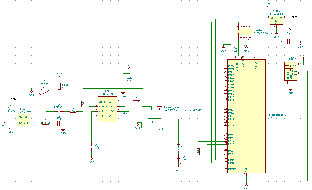
The software I used to draw my circuit schematic and traces is called KiCad. Here are some project files (all pngs) that you may use freely: schematic, traces, outline.
Milling

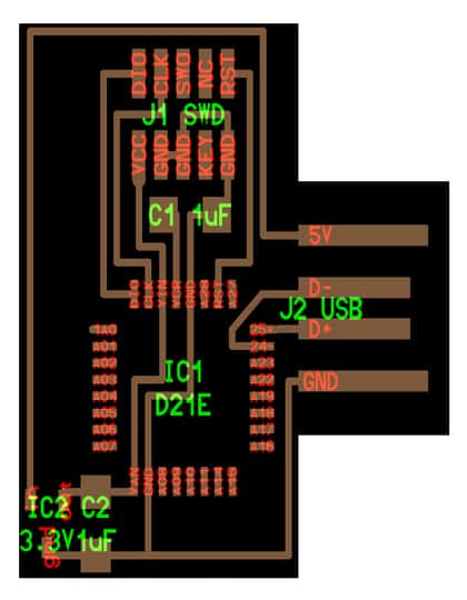
(Image 3) Shows shorted pads of the d21e MPU on the tool path generated by MODS
Normally, I wouldn't have included milling of a pcb as part of my retelling of the week, but as stated in my disclaimer, it was a source of bottleneck. I had just exported my pngs and was excited to mill on the Roland. The process is pretty much standard at this point, but I always do my checks and click view toolpath with an offset number of 1 (i.e. a single toolpath and not multiple cuts of the same path) to ensure clarity. This time however, the path seemed off. Where was my processor? As you can see in the image above, the square blob has 4 blobs that are supposed to be the pads but instead short together. This was heartbreaking and as explained earlier it would take 0.12 in tool to mill the pads, and the traces themselves would disappear. I couldn't mill in time and resorted to writing up some code and changing the footprint.
Code and Pivot

So I was having lunch with a buddy of mine and wrote some code. Writing code is a creative process so I won't ever tell anyone how they should code persay, but for this morse code a few paradigms were helpful. Buffer arrays, switch cases, and busy flags are extremely helpful in code that is executed continuously. If you have never coded for hardware before, this can be a little jarring but you have to get used to the idea of each piece of code being run constantly and the only way to keep up with all that content is to section or store the data somewhere. For me, since every letter could be decomposed into a series of dots and dashes, I decided to create a function buffer so that I could continuously read and store the functions corresponding to input letters without having to wait for my LED to finish flashing the first letter. Moreover, since there are a fixed number of outputs, use a switch case! Hardcode the functions corresponding to each letter. It is computationally more efficient despite the pain of writing more and this might be unintuitive for someone used to single execution, programmatic style approaches to input handling. Lastly, use busy flags when necessary. A large part of the power that comes from writing code for hardware is the efficiency and resource utilization granted by writing code for specific pieces whose logic can take advantage of continuous execution. However, sometimes it is necessary to somewhat reserialize your code a bit if a certain module depends on a completely processed output of another. In this case, use busy flags and that piece of code will then run a little more sequentially.
Unforuantely, I had some difficulty getting FFT to integrate with my code so I decided to ditch this idea for a different idea more related ot my final project. The original code can be found here. The pivot was to use a series of indivdually adressable LEDs as an indicator of when someone is speaking and the number of activated LEDs corresponded to the amplitude of the signal. Please see more on this idea on my finals page.