Week 11 - Networking
Design, build, and connect wired or wireless node(s) with network/bus
Plan
As it stands my final project doesn't need networking, so I devised two plans. Plan A: send trivial data from phone -> rn4871 bluetoothe module via BT and have that sent over a UART-USB converter to my computer. Plan B: Send high/low commands from computer to rn4871 where the commands come out on the TX line and go to my IO board from week 9/10 where they enter a serialized port, MPU "de-UARTS" the commands, and outputs the commands on an LED.
It wasn't easy to come up with plan B. Firstly, I had to realize that when a rn4871 received a message, it came out on the TX pin because TX stands for "transmit from" and an rn4871 is not an MPU so the data is not being stored. Secondly, my computer has bluetooth so there is no need for a second rn4871 board if I just want to demonstrate the receiving of data over BT and the use of said data. Lastly, bluetooth like any other protocol encodes the data in some scheme that must be resolved on the receiving end in software.
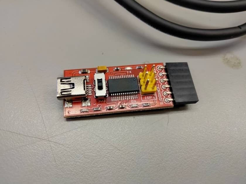
Remember to always keep in mind powering your board and the flow of data in your project. Often times we can get caught up in the design of the main components and peripherals that we forget that we need to power the board or that header in the example design corresponds to a UART header, which means to connect to your computer you need a UART - USB converter. And that is exactly what I used in my own project as shown in the image above courtesy of Dave.
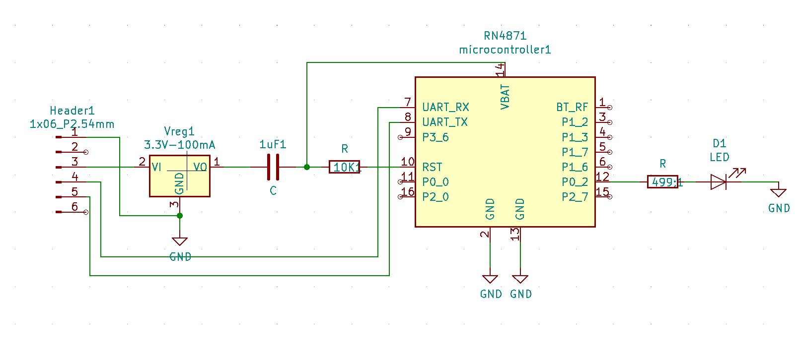
The software I used to draw my circuit schematic and traces is called KiCad. Here are some project files (all pngs) that you may use freely: schematic, traces, outline.
Milling
Milling like every week is pretty straightforward. However, my only tip this week in working with the rn4871 is about outlines and bluetooth signal. The rn4871 footprint in KiCad asks that space on one end be left with no copper because that is where th signal is sent/received and the signal can't go through copper. However, it is not necessary. If your board is close enough to your target device (e.g. computer), as long as your board is upright and near said device, there is little to no interference so there is no need to stress about the outline.
Sodering
When sodering small pins (e.g. D21E) I have two methods of sodering. 1) heat the pad and place the soder on top of the lead. Usually the soder makes direct contact with the iron but here the heat of the lead will cause the soder to melt. while it takes a little longer, it does get clean results. 2) add solder to iron tip and place gob of soder on target lead. It is a little jank but it works.
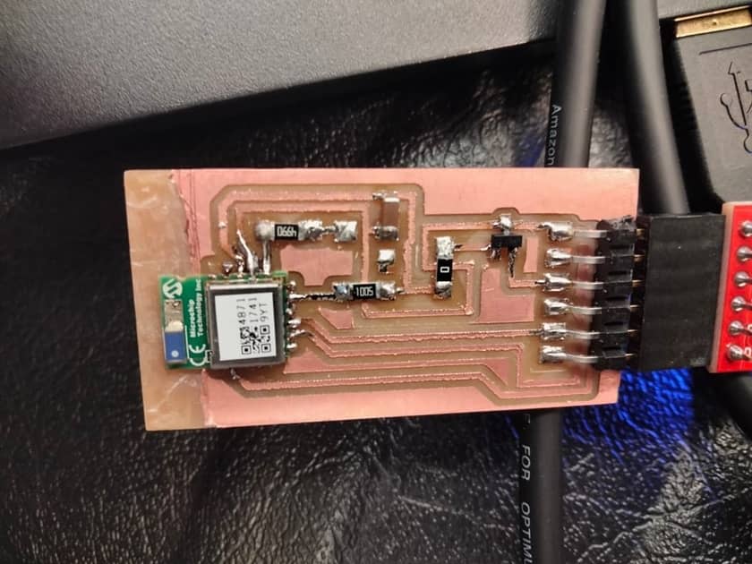
Now notice how I have a capacitor with one end on an open trace and not a pad in the above photo. In my schematic, I actually made the mistake of placing that capacitor where the 0 ohm resistor currently resides meaning both ends of the capactior were connected to VO on the voltage regulator. Doesn't make any sense, but I was able to fix it with the help of my best friend --- the 0 Ohm resistor. remember you can pull of resistors and even capacitors by heating both sides quickly and pulling with tweezers that enable high maneuverability.
Plan A
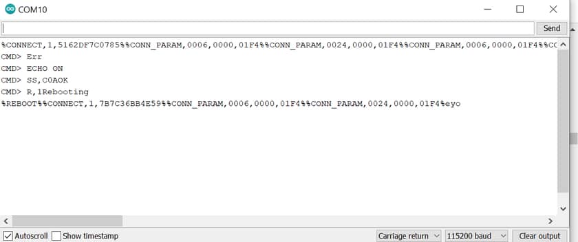
Arduino terminal that shows successful connection and receiving message "eyo" from phone
I used this tutorial.
The board didn't connect to my computer properly on the first try as noted above. However, once I confirmed I can get the board into command mode, I knew my board was working. Then I pulled up the BLE Scanning App by Bluepixel Technolgoies and scanned for my rn4871. I couldn't find it by the name "rn4871" like in the tutorial, and instead found it under BLE - XXX. When I sucessfully connected, however, I noticed I did not have the "custom service" field in the app.
Pro tip: never assume the setup for any device, especially bluetooth, is the same in a tutorial. After looking back at Neil's video of the rn4871, I found the series of commands needed to get my rn4871 in the right mode to allow the custom service field in the app to appear. And as you can see in the images I wrote "eyo" from my phone to the computer and I wrote back "whats up from the computer to my phone".
While I did end up scraping the copper off beneath my BT module, the rn4871 still works inspite of the potential signal interference as long as it is near the computer and is facing upright. The copper only interfers if the signal is trying to go through the layer of copper.
Plan B
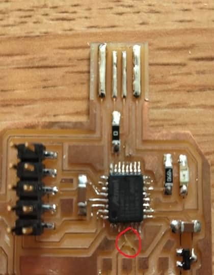
In short, plan b didn't go as planned. I milled/sodered and was ready to soder a wire to an analog pin that was open on my d21e board, make the pin take serial in software, and then plug in the sodered wire into the rx pin of my header on the rn4871 board, but I messed up. At the last minute, I ripped a trace (see circle in image to the right), and I couldn't repair the damage in time. It's unfortunate because everything (i.e. other boards, code, etc) were ready to go but I guess sending high/low commands to turn on an LED isn't too exciting.