Integrate most of the fabrication processes learned into a single design
Practicality. I didn't want another project ending up in a box somewhere that I eventually throw out when moving.
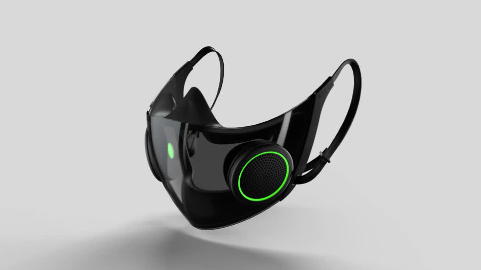
What would I actually use? It has been a pain in my side ever since the pandemic that people keep telling me
to speak up when I am wearing a mask. I know I mutter a lot but damn. So I sought out to create a mask that
essentially amplified a voice. There were a number of design principles I could optimize for and features that I
personally could desire, but I don't like designing for myself. I've done that in the past, especially in my
first few games as a amateur dev, and it just doesn't work out. I needed a living, breathing audience to facilitate
the iterative development cycle approach I take towards design. So after a few observations in my immediate
surroundings, I decided to make students my audience.
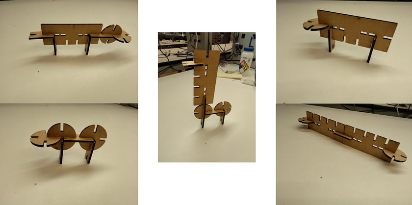
Design, lasercut, and document a parametric construction kit
Have you heard of Pictionary? The game where a player chooses a card with a short description (typically one word)
and draws it as their team members try to guess what the card said? Ok, now think "Construct-ionary". A player
chooses a card but instead of draws, they build! They build with small generic parts from a smalls set of possible
pieces and their team members try to guess what they are building! ...
Mill, Solder, and Test a Printed Circuit Board (PCB)
Milling is the bulk of the training but probably the most straightforward step. The training took about 3 hours in total:
1 hour/machine and 1 hour for soldering techniques. MIT Cypress Engineering Studio (EDS) has 2 milling machines --- Roland and Bantam --- but I prefer
the latter for the following reasons...
Design and Print an object for additive Manufacturing; Scan a 3d object
3D printing is the bulk of this week and depending on what you decide to print is super important for a few reasons.
Firstly, there are limited machines --- 1 Prusa and 1.5 Sinnohs (one of them is funky) --- in the EDS, which means you
need to coordinate with your lab mates how to run print jobs so they are done in time. Secondly, an overly complex object
will likely result in multiple print jobs and extended print times per job, hence the complexity of the object is related
exponentially to the time spent in 3D printing...
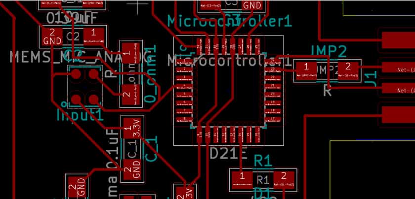
...In regards to tip 1, I made the mistake of thinking the software knew something I didn't. There was a component
I needed to connect to ground, but to do so I needed to jump the main power line. So I added a resistor between
a component output and a GND symbol in Eeschema KiCad (the schematic editor for KiCad). However, KiCad wants both
ends of the resistor to go to different places...
Be prepared for your initial design to not work. For me I knew I was betting on my initial design to work
because I didn't prototype and I didn't have any more time to spare so after removing my freshly cut parts from the stock
carefully (use screwdriver not crowbar for small parts), removing the composite nails, sanding each piece lightly, and
hammering each piece into it's respective joint, you can imagine my horror when the assembly failed due to a few design flaws...
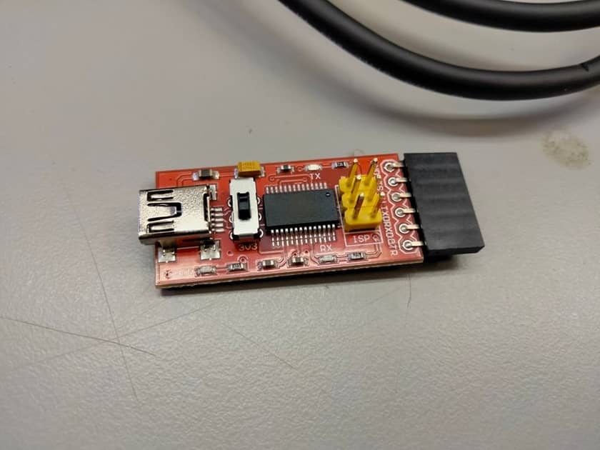
The install was straightforward and afterwards I uploaded the example blink sketch to see if my LED would turn on.
Unforunately, it did not. There were a few options here that I immediately saw 1) My computer is not reading the
usb correctly (this is actually fairly common on Linux) 2) My sketch is wrong. Turns out...
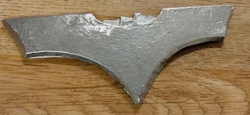
I'm Batman! ... No, don't believe it? Ok, me neither. But I am a huge fan. However, that really wasn't the point of
this particular bismuth alloy casted batarang. In my final project, there is a nose bridge that allows people
to adjust the mask to the shape of their nose, and typically these are malleable thin sheets of metal. I wanted to
see if I could cast one, but rather than create a boring nose bridge, I figured I'd make something else that was thin
and flat (more on this below) to see if the casted bismuth can deform and be machined properly at that thinness.
Add input sensor and read it; Add output sensor and program board
The current plan for my final project is to use a double sided flexible board to amplify my voice. I was going to use this week to test the circuit itself
and then later add other features (i.e. flexibility, double-sided). The board will use a microphoone (input device), an amp, and a speaker (output device)
as the main components, but what about the programming required in the output week? Speaking morse code. I will say a letter/sound to the mic and based on
some frequency, identify the letter and thus convert it to a series of dots and dashes. These dots and dashes would then be displayed on an LED.
Design, build, and connect wired or wireless node(s) with network/bus
It wasn't easy to come up with plan B. Firstly, I had to realize that when a rn4871 received a message, it came out
on the TX pin because TX stands for "transmit from" and an rn4871 is not an MPU so the data is not being stored.
Secondly, my computer has bluetooth so there is no need for a second rn4871 board if I just want to demonstrate
the receiving of data over BT and the use of said data. Lastly, bluetooth like any other protocol encodes the
data in some scheme that must be resolved on the receiving end in software. Remember to always keep in mind...
HTMAA - How to Make Almost Anything
A novice journey through making
About
I am a freestyle dancing, video game designer and student at MIT studying Computer Science and Aerospace Engineering
whose develop computational design platforms that take advantage of new rapid prototyping processes enabling the exploration of
novel design spaces via a generative, iterative design workflow