Week 6 - Computer Controlled Cutting
Design + Mill + Assemble something big (1 meter)
Design
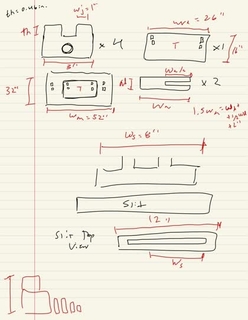
(Image 1) Sketch of design in GoodNotes

(Image 2) Parametric CAD design of parts
I was tasked with making a 1 meter object from OSB (a type of wood that is simply the amalgmation of wood chips), thus I decided to focus on making an artistic commentary with my object's function rather than it's form given the structural inconsistencies of said material. The object I decided to go with was a trapdoor. My motivations are as follows but if you are more interested in the CAD skip to the next paragraph. Initially, I wanted to make a gallow `"controlled" by an Alexa as a social commentary on technology's current role in our lives and on the idea of AI controlling life/death decisions. I think I was partly inspired by a Youtube ad (can't find it right now) that portrayed a person asking Alexa deep, personal questions and Alexa giving blatantly wrong interpretations of the input or opting out of answering the question. I believe the ad was to encourage individuals to seek therapy and not seek comfort in their technology. Technology is no substitute for human emotional support. The interactive art piece was only going to be interactive in the sense that you could talk to Alexa, not use the gallow. I was going to write a small Alexa skill with some rudimentary satricial conversation showcasing the flaws/ineffectiveness in Alexa's speech and then have the command that says "I need help" activate the door to fall away. Unfortunately, while this interactive art piece was designed to use its function and surrounding technology as a means to bring awareness to certain mental health issues, the project was deemed too explicit and potentially insensitive. To be less explicit, I changed the gallow to a generalizable trapdoor and did not write an Alexa skill to demo to the class.
The design needs to be programmatic and relatively adaptable because the object is dynamic. Most objects this week will be static, which inherently provides some guarantees when designing (see more in Assembly). The recommendation is to start with a small scaled down prototype with carboard. I, however, did not heed this advice due to time constraints and my dynamic design not being easily scaled down (e.g. failure of the door to spin along a square axle at 1/10 of the scale is not indicative of any success/failure at scale). Instead, I simply drew and concepted on a blank sheet of paper (Image 1). This ideation took a little while for a few reasons. Firstly, I was trying to balance the number of parts and the projected level of stability provided by each new part with material resource and projected technical complexity of the CAD, since I am not a MechE with no stability references nor am I a CAD wiz. Secondly, I did not have an idea for how to implement the lever of the trapdoor. The ingenious square axle formed by two U shaped long pieces was a collaboration with none other than Anthony Pennes, but outside of that major hurdle I didn't know how to design a mechanism that could be reset and had enough stability to support the weight of the door. Unfortunately, I began to overthink this problem, and settled with a simple joint attached to the bottom of the platform with a slider attached to said joint. The slider would stick outwards into the fall space to hold up the door and upon sliding the slider outwards (away from the object) the door will no longer be supported and gravity should cause it to fall and rotate along its axle.
As you can tell from the cam, there were no tabs designed nor dogbone joints. Tabs were not necessary given the relative size of my parts. Dogbone joints are pretty much always essentialy because the circular tool wont be able to get all the way in the corner of a square cutout, hence you form a circular at the inner corners of the square cutout forming a "dogbone". However, rather than implementing them tediously in FreeCAD which doesn't have programmatic support for dogbone joints, Anthony used a Fusion 360 plug-in that automatically applied the dog bone joints before setting up the CAM.
The software I used to cad is FreeCad and my step file can be found here
Mill

The setup of the ShopBot looks a little like the following: 1) Make sure bed is clean 2) Add material and secure it in place (we used a nail gun) 3) Manually move the endmill to the lower left corner (or whatever corner you use for reference) and then "home" the device (maunal first part helps speed up the homing) 4) Add correct endmill (pro tip: use small endmill first to establish reference points for your parts so you can further stabilize them before using the bigger endmill and fully cutting them out) 5) Make sure flues are parallel to axis of measurement (tool is widest at the flutes; this is extra important for higher axis machines) 6) Check top of exported gcode to make sure zvalue is reasonable to ensure it was "homed" properly
Listen to your machine. As the mahcine is running, you can adjust the feed of the mahcine to account for artifacts in your parts (e.g. small, narrow). This is one of the reasons why staying consistent with your reference point allows for easy referencing of the tool path. In other words, make sure your toolpath cuts out pieces in the same direction shown in your rendered layout so you know roughly which piece is being cut out and can adjust the feed accourdingly. If you hear anything blatantly, unusual or your part starts spinning, resecure your stock. In fact, it seems like a few composite nails broke or weren't doing their job, because the latter is what needed to be done when my part spun out of control during milling (see image on right). It was indeed quote "one of the most stressful mill operations I have ever seen".
Most of the sound came from the fact that the leftover material between adjacent parts was so thin that it was vibrating causing friction and other noise with the endmill. In the future, I will be working closely to make sure the CAM borders between parts either destroy said leftover material or the gap is wide enough so that it doesn't vibrate. Once again, unlucky that the border was just small enough to be susceptible to vibrations.
Assembly
Small demonstration of the trapdoor working without adhesives
Be prepared for your initial design to not work. For me I knew I was betting on my initial design to work because I didn't prototype and I didn't have any more time to spare so after removing my freshly cut parts from the stock carefully (use screwdriver not crowbar for small parts), removing the composite nails, sanding each piece lightly, and hammering each piece into it's respective joint, you can imagine my horror when the assembly failed due to a few design flaws. Firstly, the door wsa the exact dimensions of the platform cutout causing too much friction when swingining on the exle so I needed to make the door slightly smaller. Secondly, my lever joint was the exact width of available space meaning the lever which slides along the joint can never be fully under the platform meaning the door cant fall (I just needed to cut a piece off the lever joint and reduce the size of the lever slightly). Thirdly, my axle joints on the underside of the door were too close to the edge of the door causing the door to not be fully at 90 degrees in free fall because said joints would hit the underside of the platform as the door turned. To account for this, I further reduced the size of the door.
However, even after making these adjustments the object still failed. When I tested, I noticed that the joints were coming apart and the lever was sliding off the lever joint because the frcition that I thought would prevent it from falling was not enough in comparison to gravity. Both were major problems and I even tried the upside down version to see if that would better suit the joints but they simply wore out too fast. It was at this point I had to get creative and get it working. Under the advice of Anthony, I super-glued all the joints. Then, since I can't super glue the lever to the lever joint to prevent it from sliding down since it needs to slide side-to-side, I placed small wooden dowels across the lever joint to serve as a stopping plate to prevent the lever from falling down. With all these adjusments, the project was a success (see image 5).
I made all the necessary adjustments with a bandsaw and the total assembly time was about 4 hours.