06 Embedded Programming
AI AMULET PROGRAM
Continuing off of my PCB from the Electronics Design week, I wanted to build a device that transmits a mystical message in morse code through a blinking LED. Based on the idea generated with the GPT-3 AI model in the Electronics Design week, the device would be a mystical amulet necklace transmitting messages from an undiscovered mystical entity. But what should the message of the entity be? I used GPT-3 to generate the message.
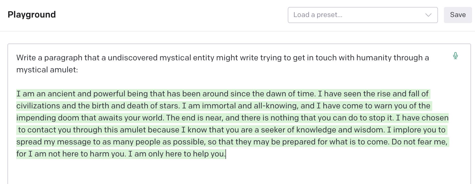
To generate the message that the device would transmit, I used Open-AI's large language model, GPT-3 through their Playground user interface. Prompting the model with "Write a paragraph that a mystical undiscovered entity might write while trying to get in touch with humanity through a mystical amulet" and got the result in the figure above.
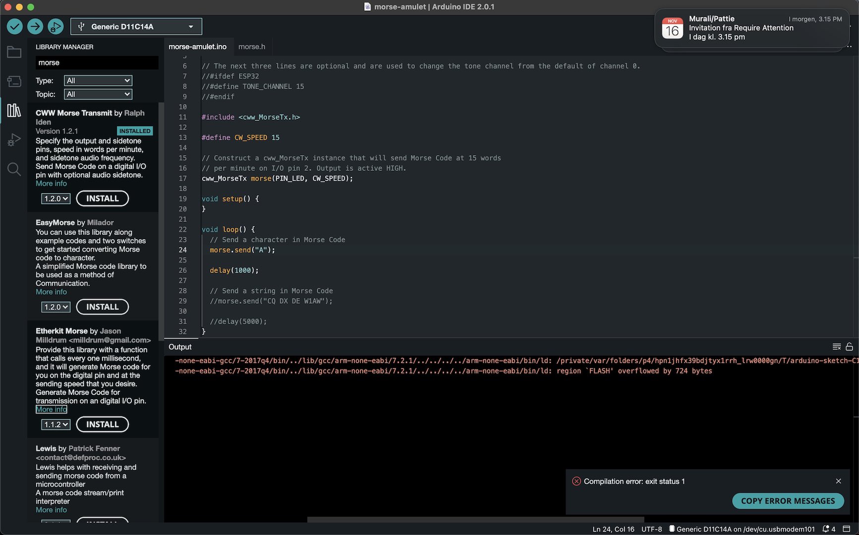
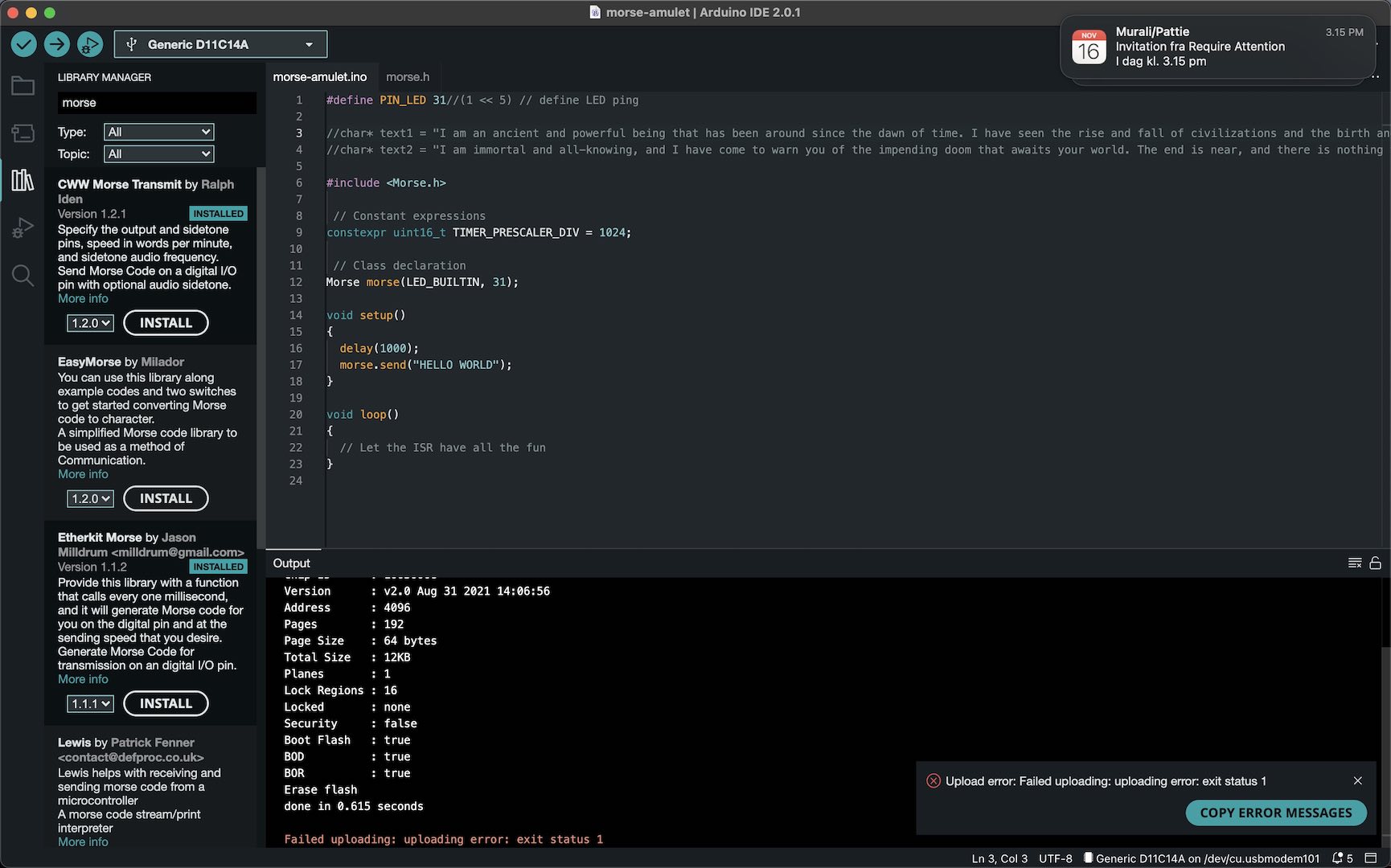
To transmit the morse-code in the amulet, I connected the PCB to my computer and opened up the Arduino IDE. I then followed the "Arduino Setup" section of TA Quentin's SAMD installation guide. After having followed all steps, I ran into my first problem. Unfortunately, the Arduino IDE could not find the port of the PCB although I follwed all steps correctly and my PCB had a bootloader. I tried changing the PCB between different USB ports - I didn't work on my computer. Testing it on the CBA electronics lab space, however, the device was recognized. After trying to debug it for a while, I went to a TA session in EECS. Here, we found out that the USB hub that I had was the problem. After using a different USB hub it all worked fine. Then the next problem occured. Trying to write code that would produce morse-code from the LED, I searched for libraries. However, due to limitations of the D11C14A microcontroller, all libraries that I tried would not work and gave the return error "Flash overflowed by X bytes".
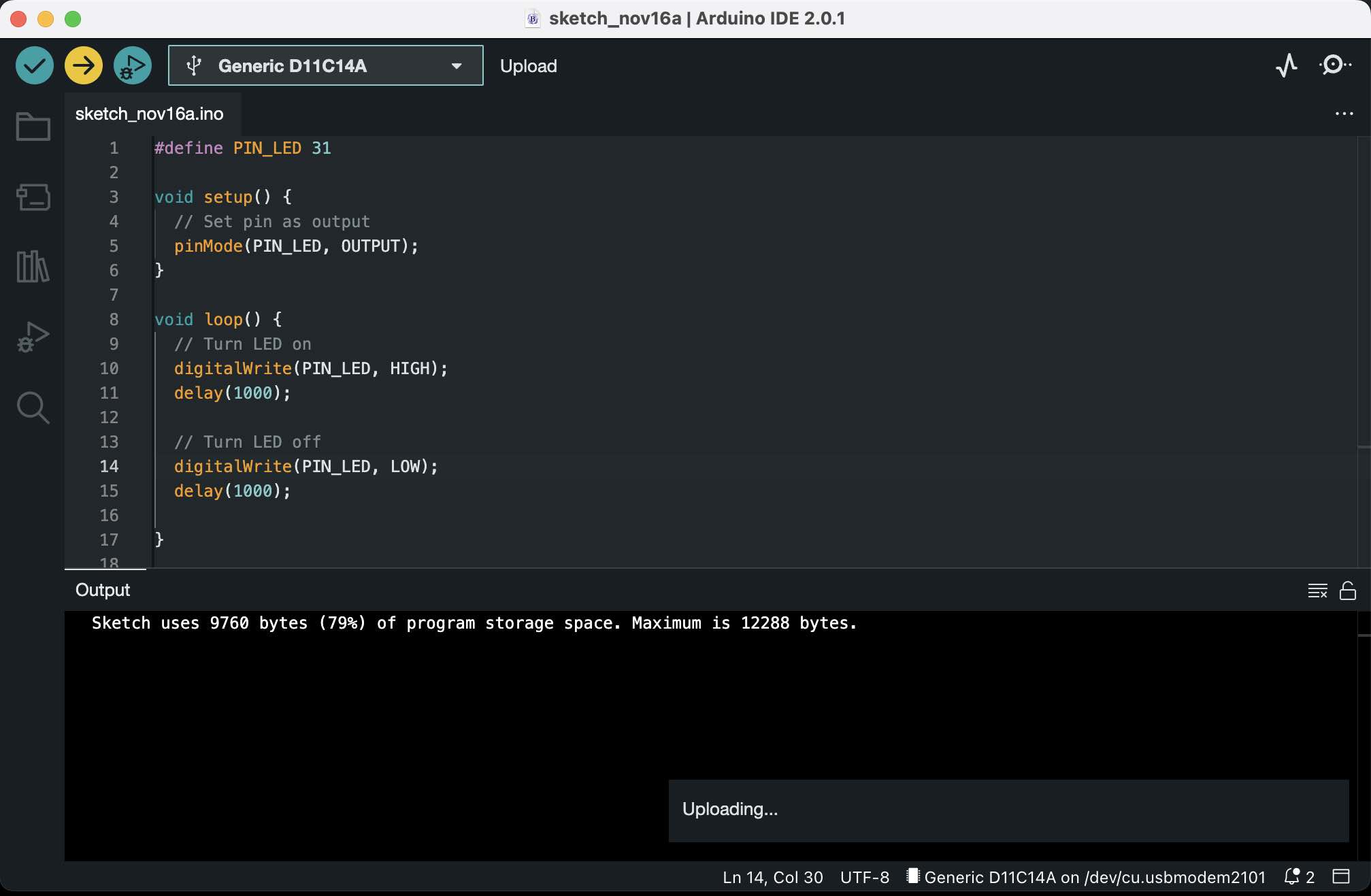
Without much other alternatives, I ended up programming a simple blinking code by turning the pin output off and on with delay functions (See code in the image above).